СИСТЕМА ПЕРЕДАЧИ ДАННЫХ
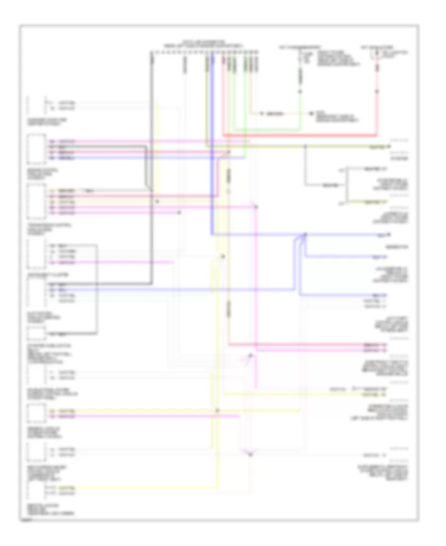
Электросхема компьютерной линии передачи данных CAN для BMW 540i 1994
 https://portal-diagnostov.com/license.html
Automotive Electricians Portal FZCO
Automotive Electricians Portal FZCO
https://portal-diagnostov.com/license.html
https://portal-diagnostov.com/license.html
Automotive Electricians Portal FZCO
Automotive Electricians Portal FZCO
Электросхема компьютерной линии передачи данных CAN для BMW 540i 1994 - Список элементов:
- A/t
- Anti-theft control module (below left side of rear seat)
- B+ junction point
- Data link connector (rear left side of engine compartment)
- Double panel power sunroof control module (in roof panel)
- Electronic throttle control module (ads ii) (behind right footwell speaker grille)
- Engine control module (dme) (in e-box)
- Front power distribution box (rear left side of engine compartment)
- Fuse f28 15a
- G103 (rear right side of engine compartment)
- General module (in rear power distribution box)
- Generator
- Hot at all times
- Hot in run and start
- Instrument cluster
- Integrated climate regulation control module (ihkr/f3) (left side of right footwell)
- Jumper plug (front power distribution box)
- M/t
- On-board computer (center of dash)
- Red
- Remote locking receiver (near rear view mirror)
- Seat/mirror memory control module (underside of left front seat)
- Slip control module (abs/asc) (in e-box)
- Starter
- Starter imobilization relay (behind left footwell speaker grill) (late production)
- Starter relay (front power distribution box)
- Transmission control module (egs) (in e-box)
- Unloader relay terminal 61 (front power distribution box)
 Čeština
 Dansk
Dansk Deutsch
 Ελληνικά
 English
 English
 Español
 Suomi
Suomi Français
 Français
 עברית
עברית Hrvatski
 Magyar
 Italiano
 日本語
日本語 한국어
한국어 Nederlands
 Polski
 Português
 Português
 Română
 Русский
 Slovenčina
 Slovenščina
 Svenska
 Türkçe
 中文 (中国)
