ANTI-LOCK BRAKES
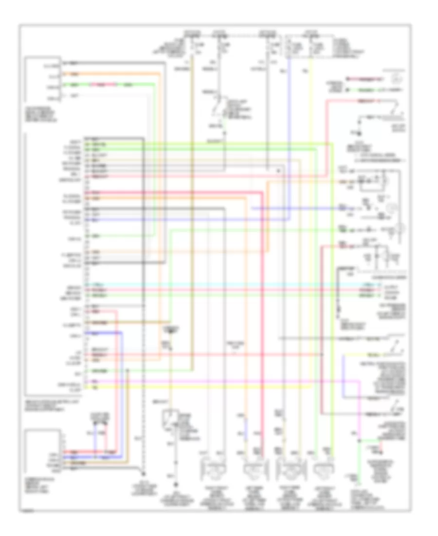
Anti-lock Brakes Wiring Diagram, with Dynamic Stability Control for Nissan Pathfinder LE 2004
 https://portal-diagnostov.com/license.html
Automotive Electricians Portal FZCO
Automotive Electricians Portal FZCO
https://portal-diagnostov.com/license.html
https://portal-diagnostov.com/license.html
Automotive Electricians Portal FZCO
Automotive Electricians Portal FZCO
List of elements for Anti-lock Brakes Wiring Diagram, with Dynamic Stability Control for Nissan Pathfinder LE 2004:
- 17u
- 39u
- 4w sw
- 4wd
- 4wd ind
- 4wd switch (part-time 4wd) (on right rear side of transfer case)
- Abs actuator & electric unit (on right side of engine compartment)
- Abs ind
- Brake fluid level low switch (on brake fluid reservoir)
- Brl 1
- Can-h
- Can-h2
- Can-l
- Can-l2
- Clu gnd
- Clu p
- Clus sp
- Combination meter
- Common
- Computer data lines system
- Data link connector (on lower dash panel, left of steering column)
- Diag-k (ddl2)
- E112 (at right side of engine compartment)
- E13 (at left front corner of engine compartment)
- Eps/tcs off
- Fl esp/tcs
- Fl power
- Fl signal
- Fr power
- Fr signal
- Fuse & fusible link box (on right front fenderwell)
- Fuse 10a
- Fuse block (j/b) (behind dash, left of steering column)
- Fuse link c 50a
- Fuse link d 30a
- Gnd
- Gnd glus
- Gnd p
- Gnd v
- High
- Hot at all times
- Hot in on or start
- Ign
- Illum
- Interior lights system
- Kl 30p
- Kl 30v
- Left front wheel sensor (at left front steering knuckle assembly)
- Left rear wheel sensor (at left rear wheel hub assembly)
- Lis
- M10
- M147 (behind right side of dash)
- M24
- M26
- Neutral position switch (part-time 4wd) (m/t: on right front side of transfer case) (a/t: on right side of transmission rear extension)
- Off
- Output
- Part-time 4wd
- Pnk
- Power
- Red
- Right front wheel sensor (at right front steering knuckle assembly)
- Right rear wheel sensor (at right rear wheel hub assembly)
- Rl power
- Rl signal
- Rr power
- Rr signal
- Sen gnd
- Sen power
- Sen sig
- Slip ind
- Steering angle sensor (behind left side of dash)
- Stop lamp switch (on bracket, above brake pedal)
- Vdc off ind
- Vdc off switch
- Vdc pressure sensor (at left rear of engine compt)
- Warning system
- With fine vision meter
- With normal meter
- Wl abs
- Wl esp/tc
- Yaw rate/side/ decel g sensor (below rear of center console)
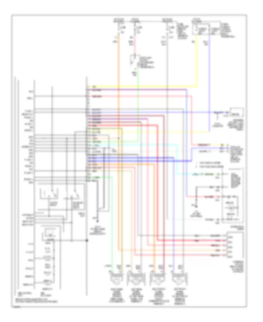
Anti-lock Brakes Wiring Diagram, without Dynamic Stability Control for Nissan Pathfinder LE 2004
 https://portal-diagnostov.com/license.html
Automotive Electricians Portal FZCO
Automotive Electricians Portal FZCO
https://portal-diagnostov.com/license.html
https://portal-diagnostov.com/license.html
Automotive Electricians Portal FZCO
Automotive Electricians Portal FZCOList of elements for Anti-lock Brakes Wiring Diagram, without Dynamic Stability Control for Nissan Pathfinder LE 2004:
- 17u
- 39u
- Abs actuator
- Abs actuator & electric unit (on right side of engine compartment)
- Abs control unit
- Abs ind
- Abs sig
- Abs st out
- Bls
- Combination meter
- Control unit (w/odo/trip meter)
- Data link connector (on lower dash panel, left of steering column)
- Diag l
- E112 (at right side side of engine compt)
- Fl in
- Fl out
- Fl ss (+)
- Fl ss (-)
- Fr in
- Fr out
- Fr ss (+)
- Fr ss (-)
- Fuse & fusible link box (on right front fenderwell)
- Fuse 10a
- Fuse block(j/b) (behind dash, left of steering column)
- Fusible link c 40a
- Fusible link d 40a
- G sensor (w/ 4wd) (below rear of center console)
- Gnd
- Gs1
- Gs2
- Gst
- Hot at all times
- Hot in on or start
- Ign
- Left front wheel sensor (at left front steering knuckle assembly)
- Left rear wheel sensor (at left rear wheel hub assembly)
- M10
- M143
- M24
- M26
- M4 (at left kick panel)
- Meter out
- Motor
- Motor relay
- Mtr relay
- Pnk
- Rear in
- Rear out
- Red
- Relay act
- Relay mon
- Relay unit
- Right front wheel sensor (at right front steering knuckle assembly)
- Right rear wheel sensor (at right rear wheel hub assembly)
- Rl ss (+)
- Rl ss (-)
- Rr ss (+)
- Rr ss (-)
- Rxd
- Sig
- Sila
- Solenoid valve relay
- Stop lamp switch (on bracket, above brake pedal)
- Transfer control unit (behind lower center dash panel)
- Txd
- Unified meter
- Vcc
- W/ 4wd
- W/ all mode 4wd
- With fine vision meter
- With normal meter

 Čeština
 Dansk
Dansk Deutsch
 Ελληνικά
 English
 English
 Español
 Suomi
Suomi Français
 Français
 עברית
עברית Hrvatski
 Magyar
 Italiano
 日本語
日本語 한국어
한국어 Nederlands
 Polski
 Português
 Português
 Română
 Русский
 Slovenčina
 Slovenščina
 Svenska
 Türkçe
