ANTI-THEFT
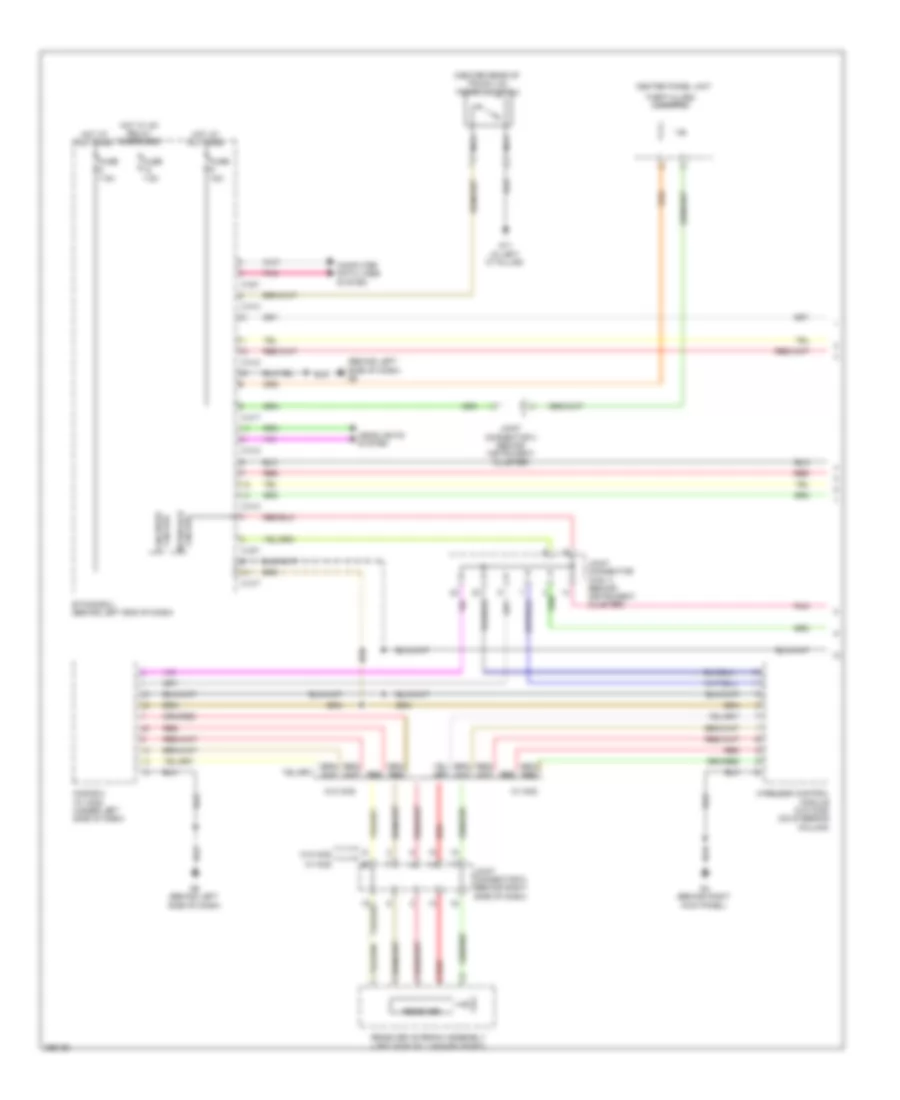
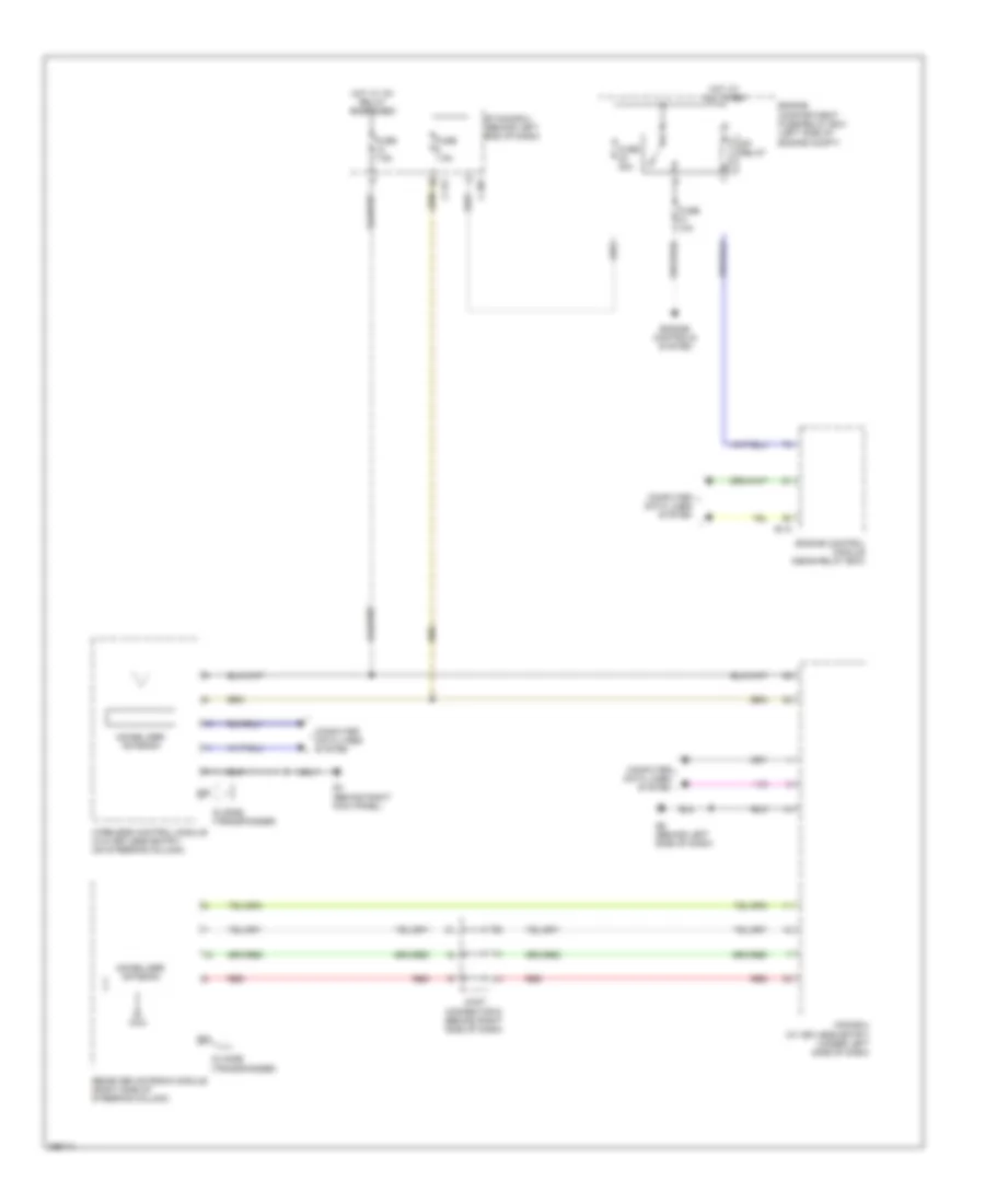
Forced Entry Wiring Diagram, Evolution (1 of 2) for Mitsubishi Lancer Evolution GSR 2008
 https://portal-diagnostov.com/license.html
Automotive Electricians Portal FZCO
Automotive Electricians Portal FZCO
https://portal-diagnostov.com/license.html
https://portal-diagnostov.com/license.html
Automotive Electricians Portal FZCO
Automotive Electricians Portal FZCO
List of elements for Forced Entry Wiring Diagram, Evolution (1 of 2) for Mitsubishi Lancer Evolution GSR 2008:
- (behind left side of dash) g6
- (center rear of trunk lid) trunk lid latch
- C-301
- C-312
- C-313
- C-317
- Can drive circuit
- Center panel unit
- Circuit interface
- Computer data lines system
- Etacs-ecu (behind left end of dash)
- Fuse 15a
- Fuse 7.5a
- G11 (in left "c" pillar)
- G4 (behind right kick panel)
- G6 (behind left side of dash)
- Headlights system
- Hot at all times
- Hot w/ ig1 relay energized
- Joint connector (can 1) (behind instrument cluster)
- Joint connector 3 (behind instrument cluster)
- Joint connector 6 (behind right side of dash)
- Kos-ecu (w/ kos) (under left side of dash)
- Nca
- Pnk
- Receiver
- Receiver antenna assembly (left side of luggage compt)
- Red
- Theft-alarm indicator
- W/ kos
- W/o kos
- Wireless control module (w/o kos) (on steering column)
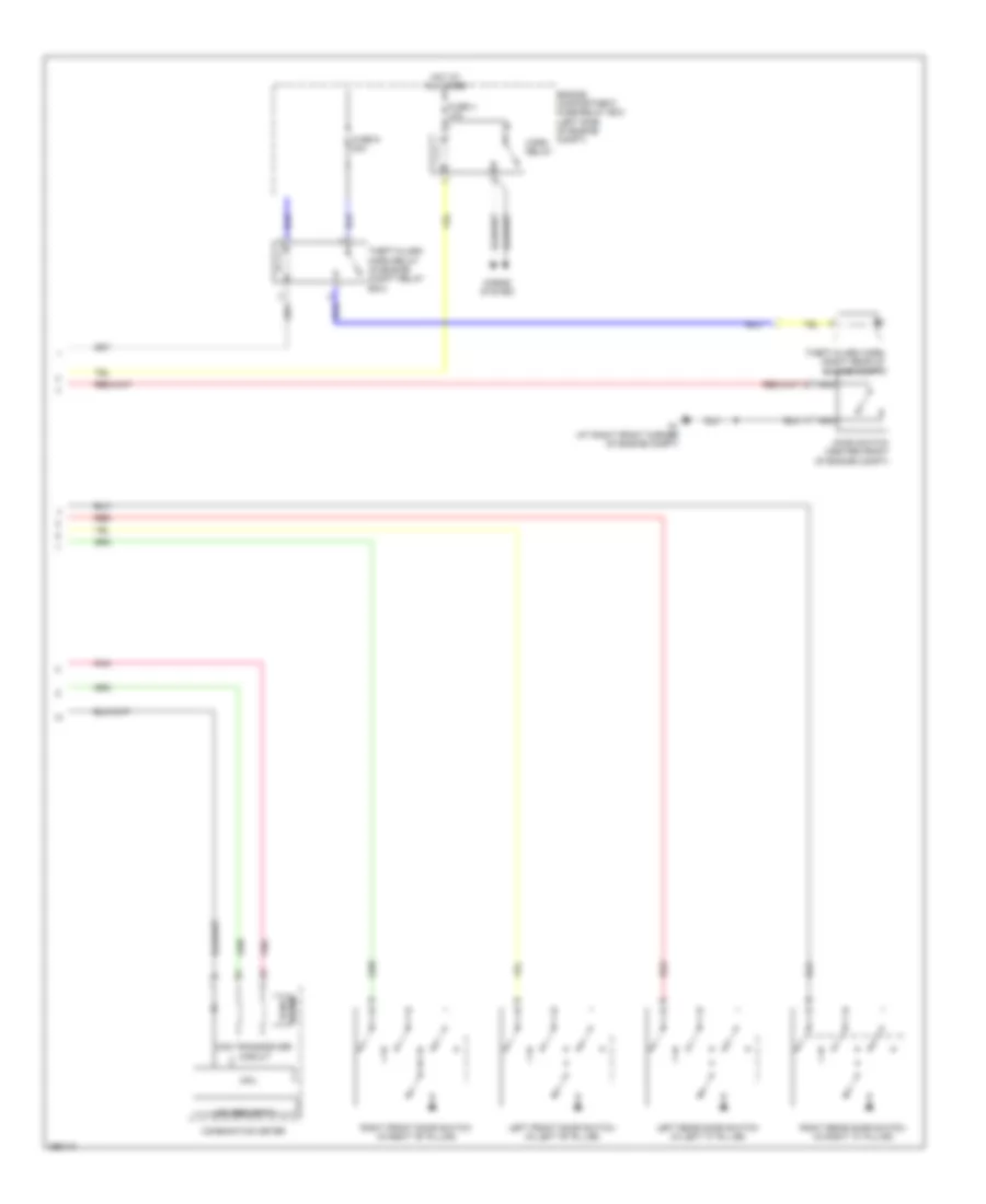
Forced Entry Wiring Diagram, Evolution (2 of 2) for Mitsubishi Lancer Evolution GSR 2008
 https://portal-diagnostov.com/license.html
Automotive Electricians Portal FZCO
Automotive Electricians Portal FZCO
https://portal-diagnostov.com/license.html
https://portal-diagnostov.com/license.html
Automotive Electricians Portal FZCO
Automotive Electricians Portal FZCOList of elements for Forced Entry Wiring Diagram, Evolution (2 of 2) for Mitsubishi Lancer Evolution GSR 2008:
- Can transceiver circuit
- Combination meter
- Cpu
- Engine compartment fuse/relay box (left side of engine compt)
- Fuse 4 10a
- Fuse 9 20a
- G1 (at right front corner of engine compt)
- Hood switch (center front of engine compt)
- Horn relay
- Horns system
- Hot at all times
- Lcd (security)
- Left front door switch (in left "b" pillar)
- Left rear door switch (in left "c" pillar)
- Nca
- Pnk
- Red
- Right front door switch (in right "b" pillar)
- Right rear door switch (in right "c" pillar)
- Theft-alarm horn (right rear of engine compt)
- Theft-alarm horn relay (in engine compt relay box)
- Tone alarm
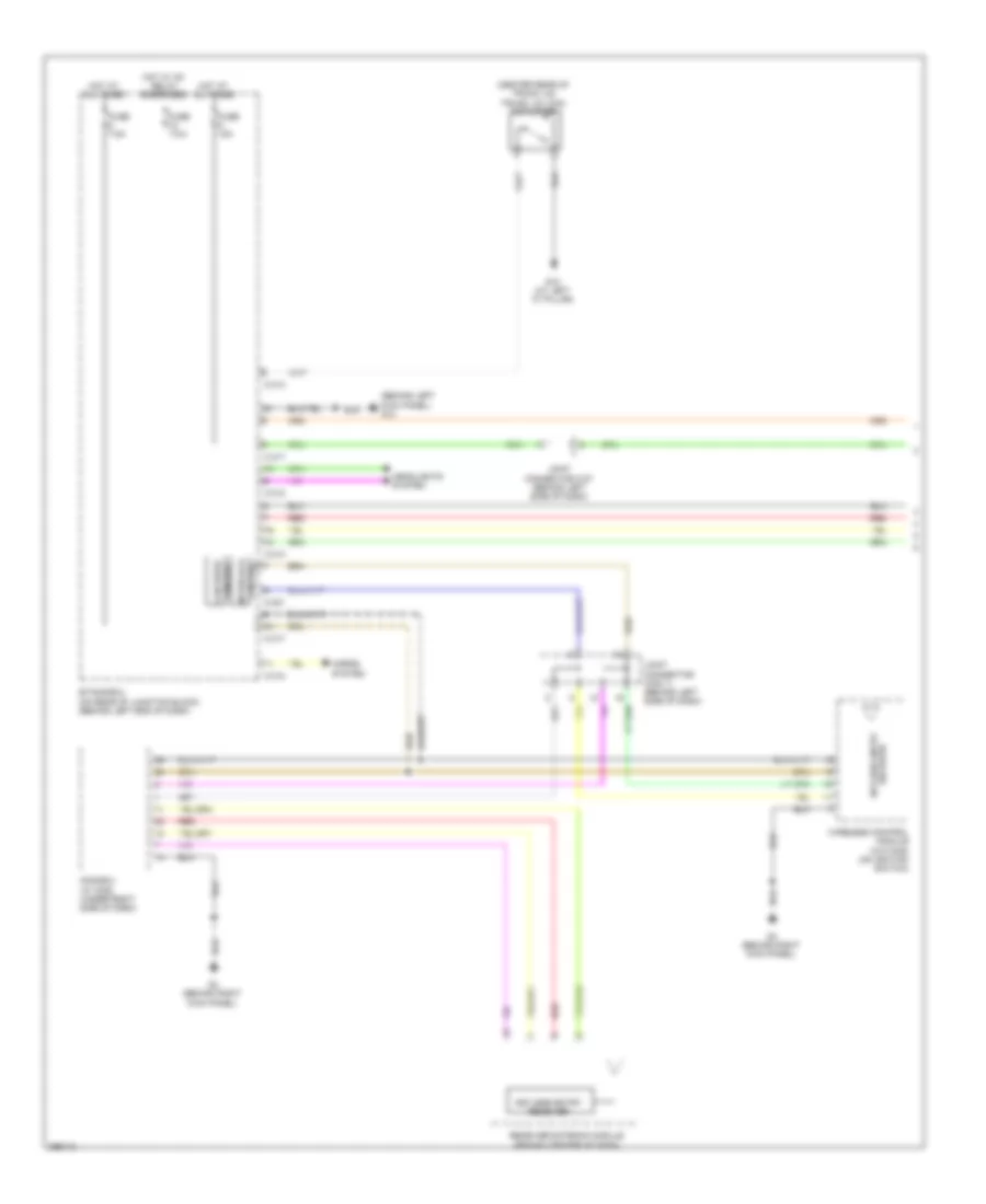
Forced Entry Wiring Diagram, Except Evolution (1 of 2) for Mitsubishi Lancer Evolution GSR 2008
 https://portal-diagnostov.com/license.html
Automotive Electricians Portal FZCO
Automotive Electricians Portal FZCO
https://portal-diagnostov.com/license.html
https://portal-diagnostov.com/license.html
Automotive Electricians Portal FZCO
Automotive Electricians Portal FZCOList of elements for Forced Entry Wiring Diagram, Except Evolution (1 of 2) for Mitsubishi Lancer Evolution GSR 2008:
- (behind left kick panel) g14
- (center rear of trunk lid) trunk lid lock actuator
- C-301
- C-312
- C-313
- C-317
- Can drive circuit
- Circuit interface
- Etacs-ecu (on rear of junction block, (behind left end of dash)
- Fuse 15a
- Fuse 7.5a
- G10 (at left "c" pillar)
- G4 (behind right kick panel)
- Headlights system
- Horns system
- Hot at all times
- Hot w/ ig1 relay energized
- Joint connector (can 1) (behind left side of dash)
- Joint connector c-07 (behind left side of dash)
- Keyless entry receiver
- Kos-ecu (w/ kos) (under right side of dash)
- Receiver antenna module (behind center of dash)
- Receiver keyless entry
- Red
- Wireless control module (w/o kos) (on ignition switch)
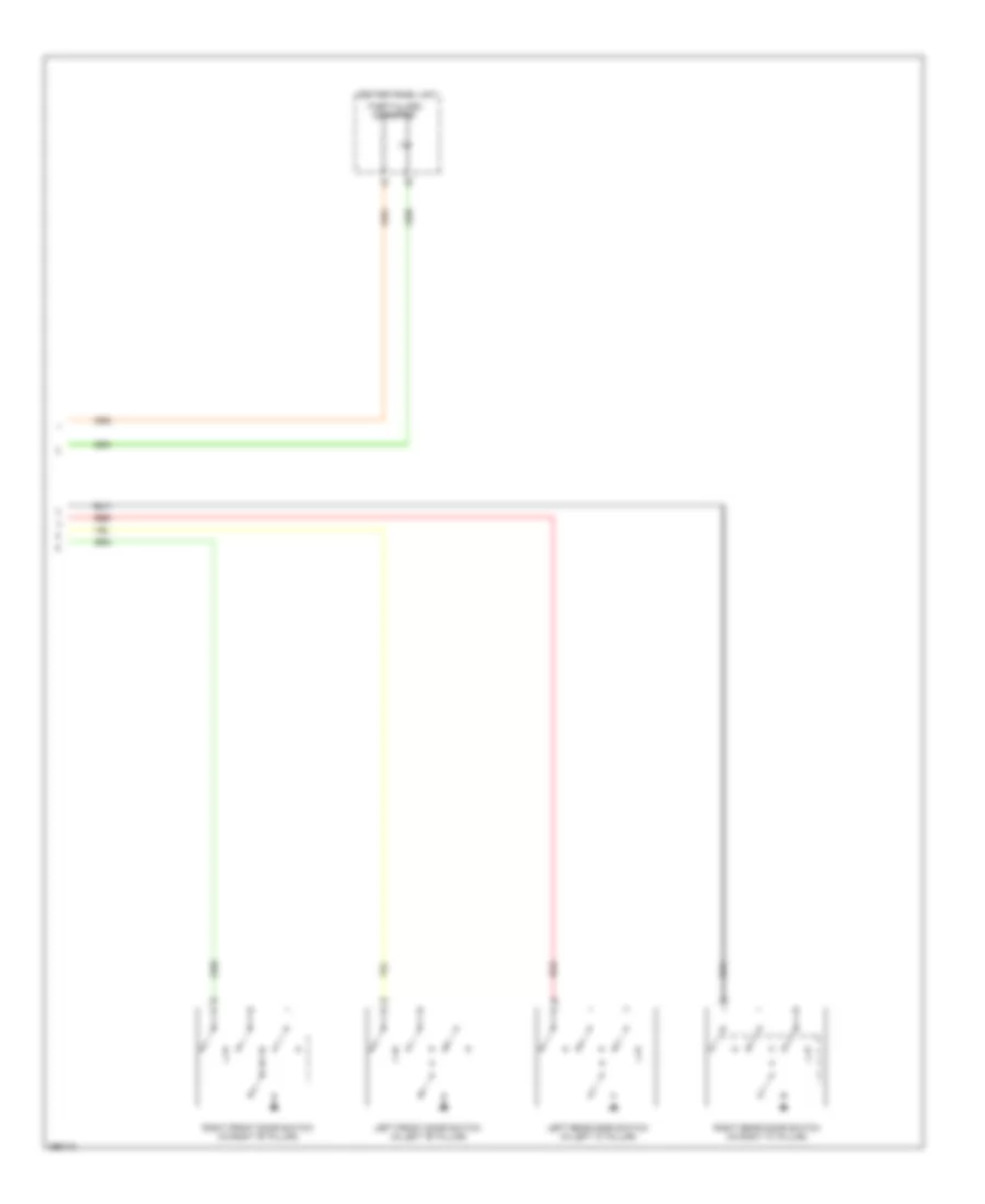
Forced Entry Wiring Diagram, Except Evolution (2 of 2) for Mitsubishi Lancer Evolution GSR 2008
 https://portal-diagnostov.com/license.html
Automotive Electricians Portal FZCO
Automotive Electricians Portal FZCO
https://portal-diagnostov.com/license.html
https://portal-diagnostov.com/license.html
Automotive Electricians Portal FZCO
Automotive Electricians Portal FZCOList of elements for Forced Entry Wiring Diagram, Except Evolution (2 of 2) for Mitsubishi Lancer Evolution GSR 2008:
- Center panel unit
- Left front door switch (in left "b" pillar)
- Left rear door switch (in left "c" pillar)
- Red
- Right front door switch (in right "b" pillar)
- Right rear door switch (in right "c" pillar)
- Theft-alarm indicator
Immobilizer Wiring Diagram, Evolution for Mitsubishi Lancer Evolution GSR 2008
 https://portal-diagnostov.com/license.html
Automotive Electricians Portal FZCO
Automotive Electricians Portal FZCO
https://portal-diagnostov.com/license.html
https://portal-diagnostov.com/license.html
Automotive Electricians Portal FZCO
Automotive Electricians Portal FZCOList of elements for Immobilizer Wiring Diagram, Evolution for Mitsubishi Lancer Evolution GSR 2008:
- B-10
- C-307
- C-317
- Computer data lines system
- Engine compartment fuse/relay box (left side of engine compt)
- Engine control module (near relay box)
- Engine controls system
- Etacs-ecu (behind left end of dash)
- Fuse 10a
- Fuse 30a
- Fuse 7.5a
- G4 (behind right kick panel)
- G6 (behind left side of dash)
- Hot at all times
- Hot w/ ig1 relay energized
- Id code (transponder)
- Immobilizer antenna
- Joint connector 6 (behind right side of dash)
- Kos-ecu (w/ keyless entry) (under left side of dash)
- Mfi relay
- Receiver antenna module (right side of steering column)
- Red
- Wireless control module (w/o keyless entry) (on steering column)
Immobilizer Wiring Diagram, Except Evolution for Mitsubishi Lancer Evolution GSR 2008
 https://portal-diagnostov.com/license.html
Automotive Electricians Portal FZCO
Automotive Electricians Portal FZCO
https://portal-diagnostov.com/license.html
https://portal-diagnostov.com/license.html
Automotive Electricians Portal FZCO
Automotive Electricians Portal FZCOList of elements for Immobilizer Wiring Diagram, Except Evolution for Mitsubishi Lancer Evolution GSR 2008:
- (left side of engine compt)
- B-109
- C-307
- C-317
- Computer data lines system
- Engine compartment fuse/relay box
- Engine control module (left rear of engine compt)
- Engine controls system
- Etacs-ecu (on rear of junction block, behind left end of dash)
- Fuse 10a
- Fuse 30a
- Fuse 7.5a
- G4 (behind right kick panel)
- Hot at all times
- Hot w/ ig1 relay energized
- Id code (transponder)
- Ignition key ring antenna
- Kos-ecu (w/ keyless entry) (under right side of dash)
- Mfi relay
- Pnk
- Receiver antenna module (behind center of dash)
- Red
- Wireless control module (w/o keyless entry) (on ignition switch)

 Čeština
 Dansk
Dansk Deutsch
 Ελληνικά
 English
 English
 Español
 Suomi
Suomi Français
 Français
 עברית
עברית Hrvatski
 Magyar
 Italiano
 日本語
日本語 한국어
한국어 Nederlands
 Polski
 Português
 Português
 Română
 Русский
 Slovenčina
 Slovenščina
 Svenska
 Türkçe
