ENGINE PERFORMANCE
4.0L
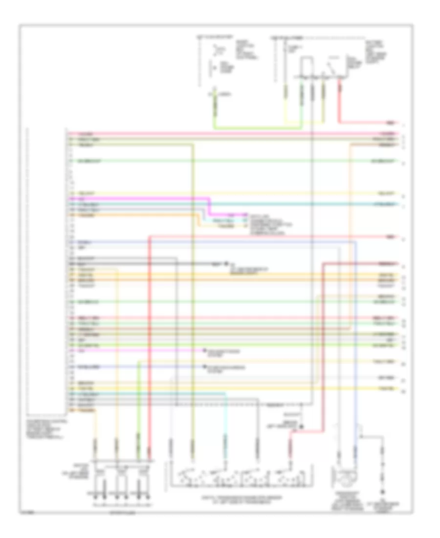
4.0L, Engine Performance Wiring Diagram (1 of 4) for Mazda B4000 2005
 https://portal-diagnostov.com/license.html
Automotive Electricians Portal FZCO
Automotive Electricians Portal FZCO
https://portal-diagnostov.com/license.html
https://portal-diagnostov.com/license.html
Automotive Electricians Portal FZCO
Automotive Electricians Portal FZCO
List of elements for 4.0L, Engine Performance Wiring Diagram (1 of 4) for Mazda B4000 2005:
- (behind left headlight)
- Air conditioning system
- Battery junction box (left rear of engine compt)
- Crankshaft position (ckp) sensor (on lower right front of engine)
- Data link connector (dlc) (fastened to bottom
- Digital transmission range (dtr) sensor (at left side of transmission)
- Fuse 11 30a
- G2 (at center rear of engine compt)
- Hot at all times
- Hot in on or start
- Ignition coil (on left rear of engine)
- Nca
- Of dash, near steering column)
- Pcm power diode
- Pcm power relay
- Powertrain control module (pcm) (at right rear of engine compt, through firewall)
- Ptc 1a
- Red
- Smart junction box (at right kick panel)
- Spark plugs
- Starting/charging system
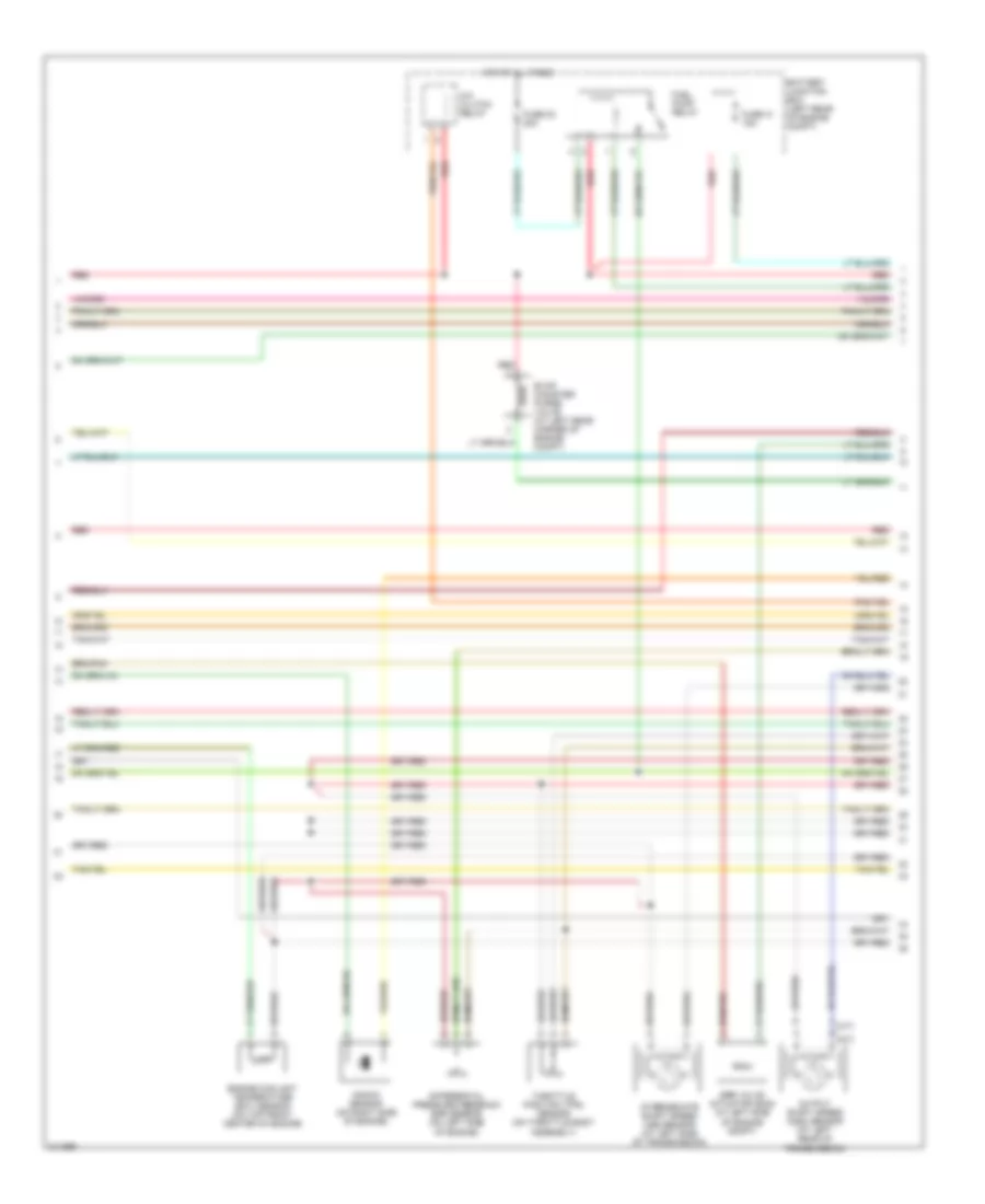
4.0L, Engine Performance Wiring Diagram (2 of 4) for Mazda B4000 2005
 https://portal-diagnostov.com/license.html
Automotive Electricians Portal FZCO
Automotive Electricians Portal FZCO
https://portal-diagnostov.com/license.html
https://portal-diagnostov.com/license.html
Automotive Electricians Portal FZCO
Automotive Electricians Portal FZCOList of elements for 4.0L, Engine Performance Wiring Diagram (2 of 4) for Mazda B4000 2005:
- (a/t)
- (m/t)
- A/c clutch relay
- Battery junction box (left rear of engine compt)
- Differential pressure feedback egr sensor (on left side of engine)
- Egr valve actuator (ecs) (at left side of engine compt)
- Engine coolant temperature (ect) sensor (on top front center of engine)
- Evap canister purge valve (at left rear corner of engine compt)
- Fuel pump relay
- Fuse 23 20a
- Fuse 41 15a
- Hot at all times
- Intermediate shaft speed (iss) sensor (at left side of transmission)
- Knock sensor (on right side of engine)
- Output shaft speed (oss) sensor (at left rear of transmission)
- Red
- Throttle position (tps) sensor (on throttle body assembly)
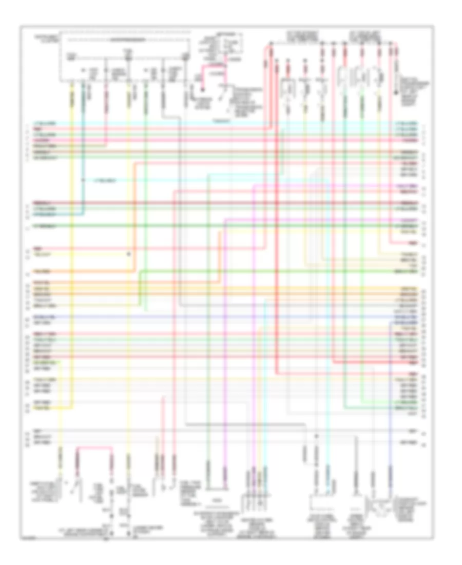
4.0L, Engine Performance Wiring Diagram (3 of 4) for Mazda B4000 2005
 https://portal-diagnostov.com/license.html
Automotive Electricians Portal FZCO
Automotive Electricians Portal FZCO
https://portal-diagnostov.com/license.html
https://portal-diagnostov.com/license.html
Automotive Electricians Portal FZCO
Automotive Electricians Portal FZCOList of elements for 4.0L, Engine Performance Wiring Diagram (3 of 4) for Mazda B4000 2005:
- (at left rear corner of engine compartment) g3
- (at top of left cylinder bank) fuel injectors
- (at top of right cylinder bank) fuel injectors
- (under center of dash) g8
- 0318-03
- 0922-101
- 0922-102
- 4wd low ind
- Camshaft position (cmp) sensor (on left side of engine)
- Check engine ind
- Check fuel cap ind
- Evaporative emission (evap) canister vent valve (under vehicle, on frame cross support)
- Exterior lights system
- Four wheel drive control module (behind center of dash)
- Fuel gauge sensor
- Fuel lev sig
- Fuel pump
- Fuel tank pressure sensor (at fuel tank assembly)
- Fuel tank unit (in fuel tank
- Fuse 10a
- Heated oxygen sensor (ho2s) 22 (at right rear of engine, in exhaust)
- Hot in on
- Ignition transformer capacitor 1 (at left rear of engine compt)
- Inertia fuel shut-off (ifs) switch (at right kick panel)
- Instrument cluster
- J-2280b
- Microprocessor
- Nca
- O/d off ind
- Red
- Red/pnk
- Smart junction box (at right kick panel)
- Speed control servo (in right rear of engine compt)
- Tach sig
- Tan
- Transmission control switch (on end of transmission selector lever)
- Vss sig
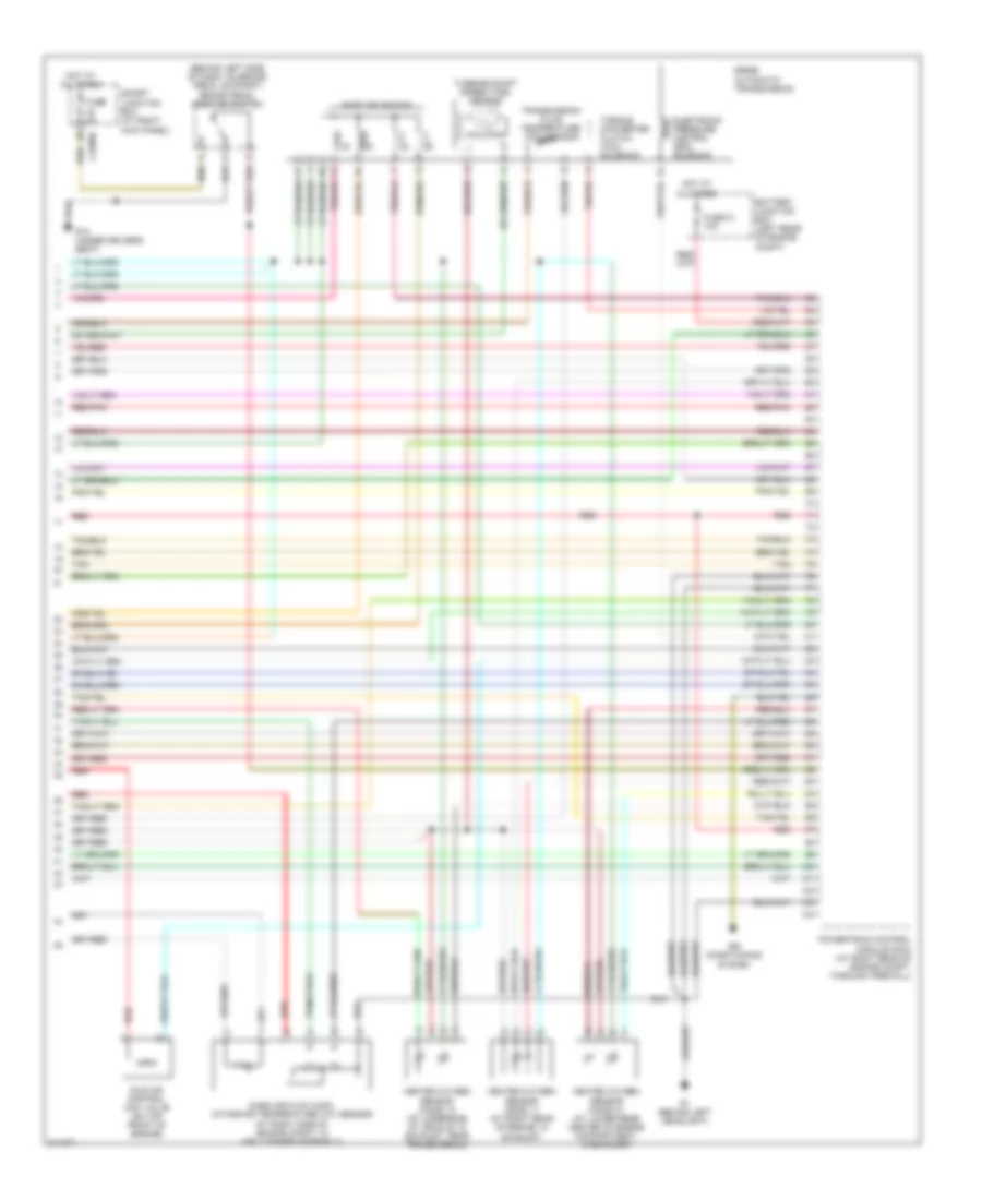
4.0L, Engine Performance Wiring Diagram (4 of 4) for Mazda B4000 2005
 https://portal-diagnostov.com/license.html
Automotive Electricians Portal FZCO
Automotive Electricians Portal FZCO
https://portal-diagnostov.com/license.html
https://portal-diagnostov.com/license.html
Automotive Electricians Portal FZCO
Automotive Electricians Portal FZCOList of elements for 4.0L, Engine Performance Wiring Diagram (4 of 4) for Mazda B4000 2005:
- (behind left side of dash, on brake pedal support) brake pedal position switch
- 5r55e automatic transmission
- Air conditioning system
- Battery junction box (left rear of engine compt)
- Electronic pressure control (epc) solenoid
- Fuse 21 10a
- Fuse 5a
- G1 (behind left headlight)
- G10 (under driver's seat)
- Heated oxygen sensor (ho2s) 11 (at right rear of engine, in exhaust)
- Heated oxygen sensor (ho2s) 12 (at underside of vehicle, in exhaust, near transmission)
- Heated oxygen sensor (ho2s) 21 (at lower rear center of engine compartment, in exhaust)
- Hot at all times
- Idle air control (iac) valve (on top front of engine)
- J-2280b
- Mass air flow (maf)/ intake air temperature (iat) sensor (at right side of engine compt, in air cleaner assembly)
- Powertrain control module (pcm) (at right rear of engine compt, through firewall)
- Red
- Red/pnk
- Shift solenoids
- Smart junction box (at right kick panel)
- Tan
- Torque converter clutch (tcc) solenoid
- Transmission fluid temperature (tft) sensor
- Turbine shaft speed (tss) sensor

 Čeština
 Dansk
Dansk Deutsch
 Ελληνικά
 English
 English
 Español
 Suomi
Suomi Français
 Français
 עברית
עברית Hrvatski
 Magyar
 Italiano
 日本語
日本語 한국어
한국어 Nederlands
 Polski
 Português
 Português
 Română
 Русский
 Slovenčina
 Slovenščina
 Svenska
 Türkçe
