ENGINE PERFORMANCE
1.8L
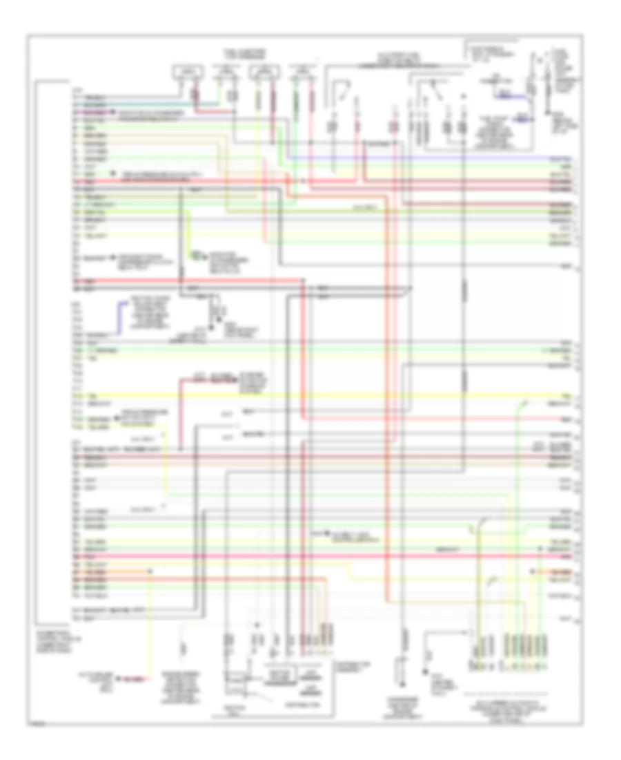
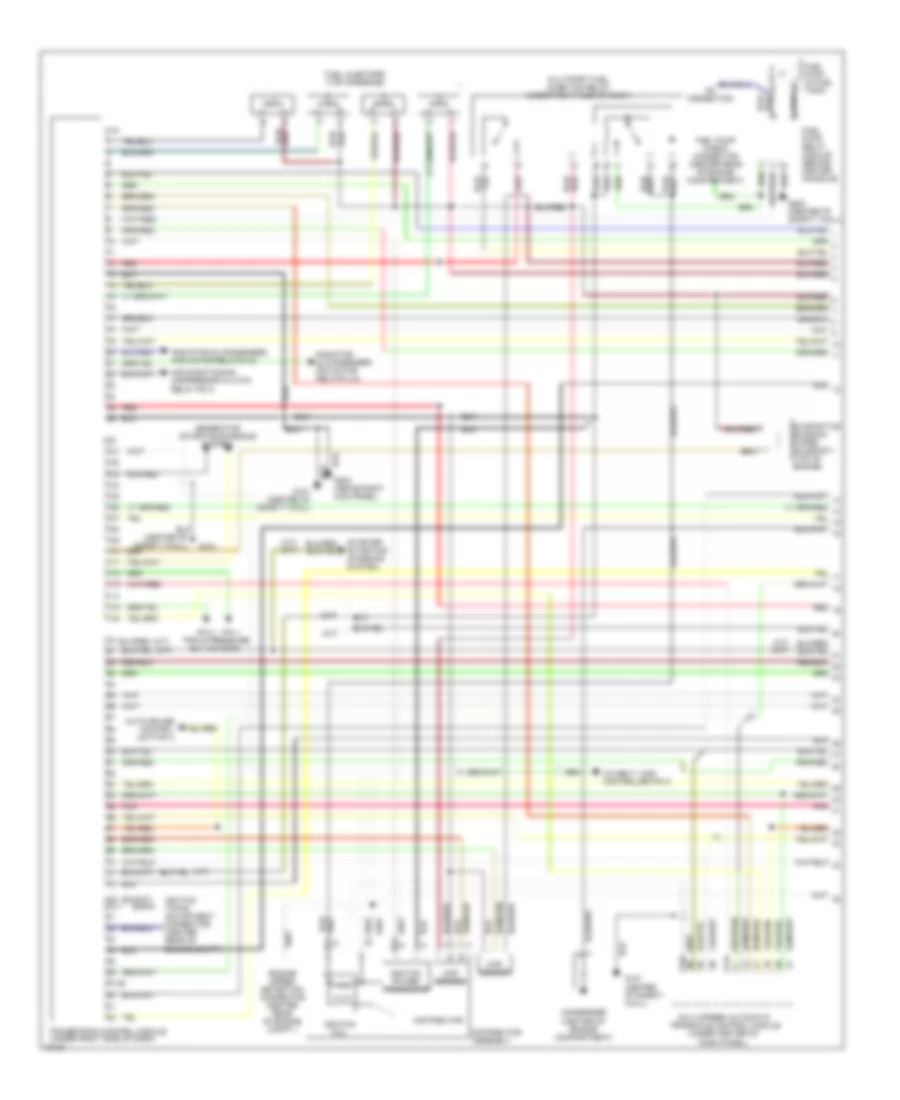
1.8L, Engine Performance Wiring Diagrams, California (1 of 2) for Mitsubishi Expo 1995

List of elements for 1.8L, Engine Performance Wiring Diagrams, California (1 of 2) for Mitsubishi Expo 1995:
- (a/t)
- (a/t) (m/t)
- (center of safety wall)
- (expo)
- (m/t)
- (summit)
- * cb28%% (summit)
- 37-39
- A/c belt lock controller pin 2
- Air conditioning compressor clutch relay pin 3
- Auto-cruise control unit-pin 4
- B14
- B24
- B26
- C19
- C20
- C21
- C24
- C25
- C81 c21-1
- Ckp sensor
- Cmp sensor
- Condenser (center of engine compartment)
- Dash panel)
- Distributor
- Distributor assembly
- Elc 4-speed automatic transaxle control module (under center of
- Engine speed detection connector (center rear of engine compt.)
- Fuel injectors (top of engine)
- Fuel pump (in fuel tank)
- Fuel pump check connector (center rear of engine compartment)
- G121
- G121 (center of safety wall)
- G202 (behind left side of i/p)
- G203 (above right kick panel)
- Generator (starting/charging system)
- Ignition coil
- Ignition power transistor
- Ignition timing adjustment connector (center rear of engine compt.)
- Multiport fuel injection relay (under right center of dash)
- No connection
- Pin 1
- Pin 4
- Pnk
- Powertrain control module (under right side of dash)
- Radiator (& condenser) fan motor relays (lo)
- Radiator (& condenser) fan motor relays (hi)
- Red
- Starter (starting/ charging system)
- Triple pressure sw. (a/c sys.)
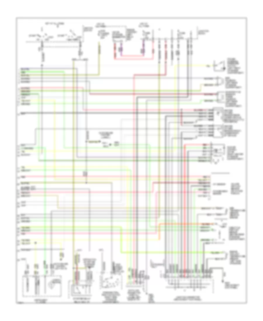
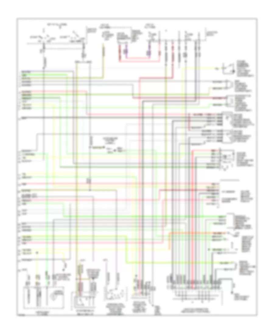
1.8L, Engine Performance Wiring Diagrams, California (2 of 2) for Mitsubishi Expo 1995
List of elements for 1.8L, Engine Performance Wiring Diagrams, California (2 of 2) for Mitsubishi Expo 1995:
- (a/t)
- (a/t) (m/t)
- (expo)
- (m/t)
- (summit)
- A09
- Acc
- Acc on
- Atmospheric sensor
- Auto-cruise control unit
- Auto-cruise control unit pin 19
- C02
- C38
- C57
- C58
- C61
- C64
- C66
- C67
- C71
- C77
- Check engine
- Cpp switch (starting/ charging system)
- Ctp sw
- D02
- D03
- Data link connector (partial) (lower left side of i/p)
- Egr solenoid (left rear of engine compartment)
- Engine compart- ment relay box
- Engine coolant temperature sensor (left side of engine)
- Evaporative emission purge solenoid (left rear of engine compartment)
- Fuse 10a
- Fusible link 3 20a
- G202 (left side of i/p)
- G203 (above right kick panel)
- Hall ic
- Heated oxygen sensor (front) (under front of vehicle)
- Heated oxygen sensor (rear) (under vehicle behind catalytic convertor)
- Hot at all times
- Iat sensor
- Idle air control motor (right center of engine compartment)
- Ignition switch
- Instrument cluster
- Iod or storage connector
- Junction block
- Junction connector (above right kick panel)
- Lock
- Manifold differential pressure sensor (center rear of eng. compt.)
- Nca
- Park/neutral position switch (right side of engine compartment)
- Pin 1
- Pin 5
- Pnk
- Power steering pressure switch (left front of engine compartment)
- Red
- Reed (speedometer)
- Relay box: i/p
- Start
- Starter relay
- Sub
- Tachometer
- Throttle position sensor (center rear of engine compt.)
- Volume air flow sensor (on intake plenum)
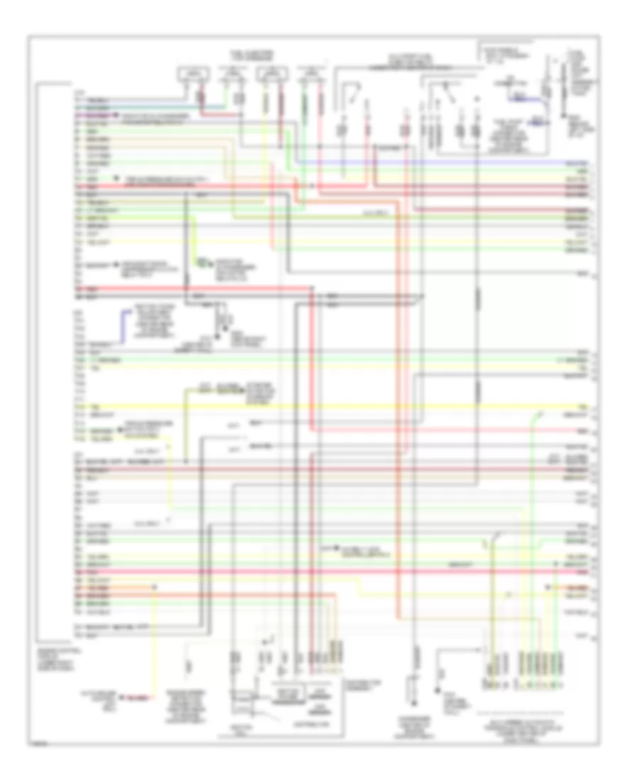
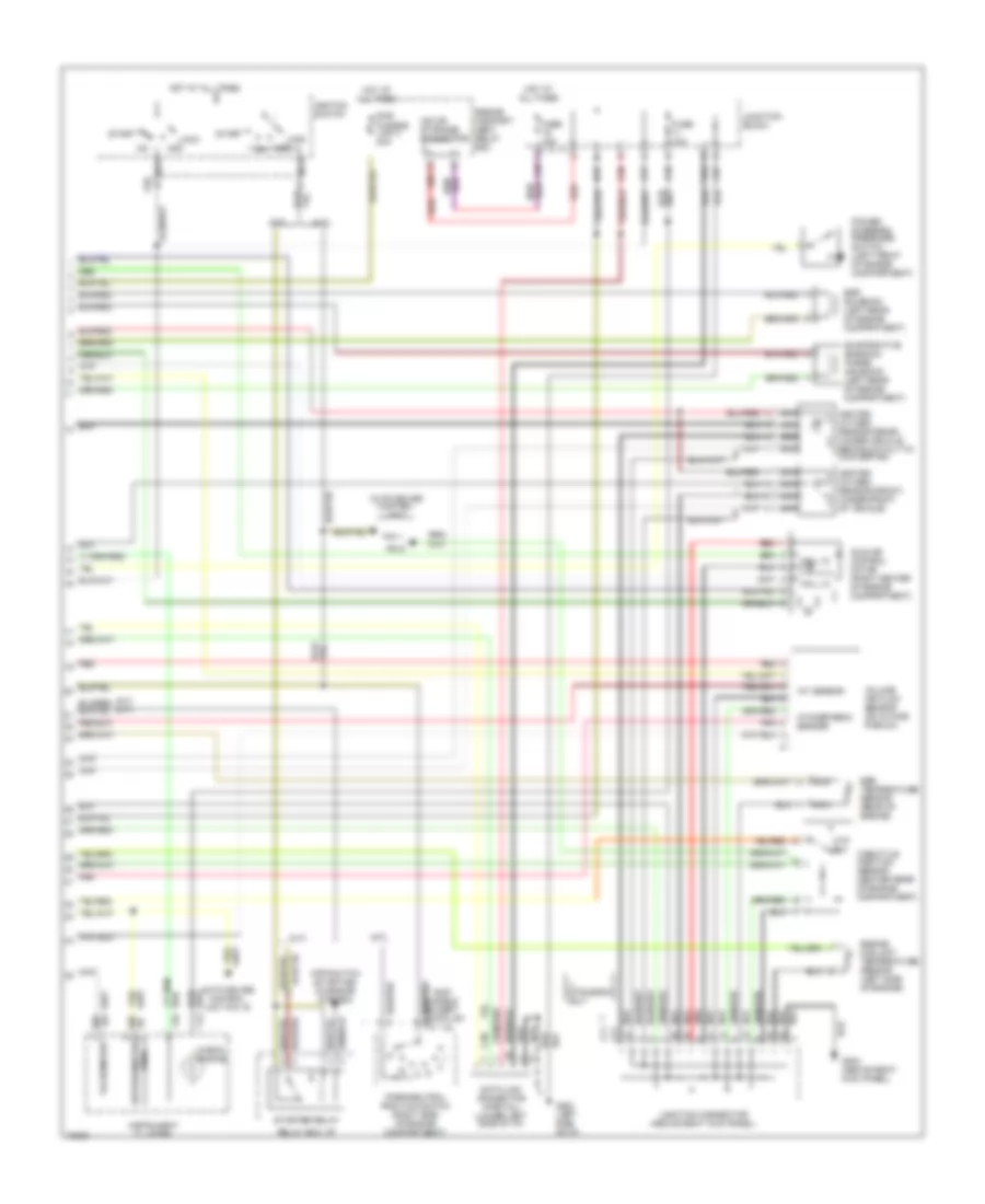
1.8L, Engine Performance Wiring Diagrams, Federal (1 of 2) for Mitsubishi Expo 1995
List of elements for 1.8L, Engine Performance Wiring Diagrams, Federal (1 of 2) for Mitsubishi Expo 1995:
- (a/t)
- (a/t) (m/t)
- (m/t)
- * awd models
- 2.4l only
- A/c belt lock controller pin 2
- Air conditioning compressor clutch relay pin 3
- Auto-cruise control unit pin 4
- B14
- B24
- C19
- C20
- C21
- C24
- C25
- Ckp sensor
- Cmp sensor
- Condenser (center of engine compartment)
- Dash panel)
- Distributor
- Distributor assembly
- Elc 4-speed automatic transaxle control module (under center of
- Engine speed detection connector (center rear of engine compartment)
- Exc. mitsubishi w/ 1.8l
- Fuel injectors (top of engine)
- Fuel pump and gauge unit assembly (in fuel tank)
- Fuel pump check connector (center rear of engine compartment)
- G121 (center of safety wall)
- G202 (behind left side of i/p)
- G203 (above right kick panel)
- Ignition coil
- Ignition power transistor
- Ignition timing adjustment connector (center rear of engine compartment)
- Multiport fuel injection relay (under right center of dash)
- No connection
- Pnk
- Powertrain control module (under right side of dash)
- Radiator (& condenser) fan motor relays (lo)
- Radiator (& condenser) fan motor relays (hi)
- Red
- Starter (starting/ charging system)
- Triple pressure switch pin 1 (air conditioning system)
- Triple pressure switch pin 4 (a/c system)
1.8L, Engine Performance Wiring Diagrams, Federal (2 of 2) for Mitsubishi Expo 1995
List of elements for 1.8L, Engine Performance Wiring Diagrams, Federal (2 of 2) for Mitsubishi Expo 1995:
- (a/t)
- (a/t) (m/t)
- (m/t)
- (speedometer) reed
- * awd models except expo lrv w/ 1.8l
- ** mitsubishi only
- A09
- Acc
- Acc on
- Atmospheric sensor
- Auto-cruise control unit
- Auto-cruise control unit pin 19
- C02
- C38
- C57
- C58
- C61
- C64
- C66
- C67
- C71
- C77
- Check engine
- Cpp switch (starting/ charging system)
- Ctp sw
- D02
- D03
- Data link connector (partial) (lower left side of i/p)
- Egr solenoid (left rear of engine compartment)
- Egr temperature sensor (rear of engine)
- Engine compart- ment relay box
- Engine coolant temperature sensor (left side of engine)
- Evaporative emission purge solenoid (left rear of engine compartment)
- Fuse 10a
- Fusible link 3 20a
- G202 (left side of i/p)
- G203 (above right kick panel)
- Hall ic
- Heated oxygen sensor (front) (under front of vehicle)
- Heated oxygen sensor (rear) (under vehicle behind catalytic convertor)
- Hot at all times
- Iat sensor
- Idle air control motor (right center of engine compartment)
- Ignition switch
- Instrument cluster
- Iod or storage connector
- Junction block
- Junction connector (above right kick panel)
- Lock
- Nca
- Park/neutral position switch (right side of engine compartment)
- Pin 1
- Pin 5
- Pnk
- Power steering pressure switch (left front of engine compartment)
- Red
- Relay box: i/p
- Start
- Starter relay
- Sub
- Tachometer
- Throttle position sensor (center rear of engine compartment)
- Volume air flow sensor (on intake plenum)
2.4L
2.4L, Engine Performance Wiring Diagrams, Calif. AWD & Federal AWD/FWD (1 of 2) for Mitsubishi Expo 1995
List of elements for 2.4L, Engine Performance Wiring Diagrams, Calif. AWD & Federal AWD/FWD (1 of 2) for Mitsubishi Expo 1995:
- (a/t)
- (a/t) (m/t)
- (m/t)
- * awd models
- 2.4l only
- A/c belt lock controller pin 2
- Air conditioning compressor clutch relay pin 3
- Auto-cruise control unit pin 4
- B14
- B24
- C19
- C20
- C21
- C24
- C25
- Ckp sensor
- Cmp sensor
- Condenser (center of engine compartment)
- Dash panel)
- Distributor
- Distributor assembly
- Elc 4-speed automatic transaxle control module (under center of
- Engine control module (under right side of dash)
- Engine speed detection connector (center rear of engine compartment)
- Exc. mitsubishi w/ 1.8l
- Fuel injectors (top of engine)
- Fuel pump and gauge unit assembly (in fuel tank)
- Fuel pump check connector (center rear of engine compartment)
- G121 (center of safety wall)
- G202 (behind left side of i/p)
- G203 (above right kick panel)
- Ignition coil
- Ignition power transistor
- Ignition timing adjustment connector (center rear of engine compartment)
- Multiport fuel injection relay (under right center of dash)
- No connection
- Pnk
- Radiator (& condenser) fan motor relays (lo)
- Radiator (& condenser) fan motor relays (hi)
- Red
- Starter (starting/ charging system)
- Triple pressure switch pin 1 (air conditioning system)
- Triple pressure switch pin 4 (a/c system)
2.4L, Engine Performance Wiring Diagrams, Calif. AWD & Federal AWD/FWD (2 of 2) for Mitsubishi Expo 1995
List of elements for 2.4L, Engine Performance Wiring Diagrams, Calif. AWD & Federal AWD/FWD (2 of 2) for Mitsubishi Expo 1995:
- (a/t)
- (a/t) (m/t)
- (m/t)
- (speedometer) reed
- * awd models except expo lrv w/ 1.8l
- ** mitsubishi only
- A09
- Acc
- Acc on
- Atmospheric sensor
- Auto-cruise control unit
- Auto-cruise control unit pin 19
- C02
- C38
- C57
- C58
- C61
- C64
- C66
- C67
- C71
- C77
- Check engine
- Cpp switch (starting/ charging system)
- Ctp sw
- D02
- D03
- Data link connector (partial) (lower left side of i/p)
- Egr solenoid (left rear of engine compartment)
- Egr temperature sensor (rear of engine)
- Engine compart- ment relay box
- Engine coolant temperature sensor (left side of engine)
- Evaporative emission purge solenoid (left rear of engine compartment)
- Fuse 10a
- Fusible link 3 20a
- G202 (left side of i/p)
- G203 (above right kick panel)
- Hall ic
- Heated oxygen sensor (front) (under front of vehicle)
- Heated oxygen sensor (rear) (under vehicle behind catalytic convertor)
- Hot at all times
- Iat sensor
- Idle air control motor (right center of engine compartment)
- Ignition switch
- Instrument cluster
- Iod or storage connector
- Junction block
- Junction connector (above right kick panel)
- Lock
- Nca
- Park/neutral position switch (right side of engine compartment)
- Pin 1
- Pin 5
- Pnk
- Power steering pressure switch (left front of engine compartment)
- Red
- Relay box: i/p
- Start
- Starter relay
- Sub
- Tachometer
- Throttle position sensor (center rear of engine compartment)
- Volume air flow sensor (on intake plenum)
2.4L, Engine Performance Wiring Diagrams, California FWD (1 of 2) for Mitsubishi Expo 1995
List of elements for 2.4L, Engine Performance Wiring Diagrams, California FWD (1 of 2) for Mitsubishi Expo 1995:
- (a/t)
- (a/t) (m/t)
- (expo)
- (m/t)
- (summit)
- 37-39
- A/c belt lock controller pin 2
- Air conditioning compressor clutch relay pin 3
- Auto-cruise control unit-pin 4
- B14
- B24
- C19
- C20
- C21
- C24
- C25
- C82 c21-1
- Ckp sensor
- Cmp sensor
- Condenser (center of engine compartment)
- Dash panel)
- Distributor
- Distributor assembly
- Elc 4-speed automatic transaxle control module (under center of
- Engine speed detection connector (center rear of engine compt.)
- Evapoative emission purge solenoid 1 (top of engine)
- Fuel injectors (top of engine)
- Fuel pump (in fuel tank)
- Fuel pump check connector (center rear of engine compartment)
- Fuel pump relay module (behind center console)
- G121
- G121 (center of safety wall)
- G202 (center of safety wall)
- Generator (starting/charging system)
- Ignition coil
- Ignition power transistor
- Ignition timing adjustment connector (center rear of engine compt.)
- Multiport fuel injection relay (under right side of dash)
- No connection
- Pin 1
- Pin 4
- Pnk
- Powertrain control module (under right side of dash)
- Radiator (& condenser) fan motor relays (lo)
- Radiator (& condenser) fan motor relays (hi)
- Red
- Starter (starting/ charging system)
- Triple pressure sw. (a/c sys.)
2.4L, Engine Performance Wiring Diagrams, California FWD (2 of 2) for Mitsubishi Expo 1995
List of elements for 2.4L, Engine Performance Wiring Diagrams, California FWD (2 of 2) for Mitsubishi Expo 1995:
- (a/t)
- (a/t) (m/t)
- (expo)
- (m/t)
- (summit)
- A09x
- Acc
- Acc on
- Atmospheric sensor
- Auto-cruise control unit
- Auto-cruise control unit pin 19
- C02
- C38
- C57
- C58
- C61
- C64
- C66
- C67
- C71
- C77
- Check engine
- Cpp switch (starting/ charging system)
- Ctp sw
- D02
- D03
- Data link connector (partial) (lower left side of i/p)
- Egr solenoid (left rear of engine compartment)
- Engine compart- ment relay box
- Engine coolant temperature sensor (right front of engine)
- Evaporative emission purge solenoid (left rear of engine compartment)
- Fuse 10a
- Fusible link 3 20a
- G202 (left side of i/p)
- G203 (above right kick panel)
- Hall ic
- Heated oxygen sensor (front) (under front of vehicle)
- Heated oxygen sensor (rear) (under vehicle behind catalytic convertor)
- Hot at all times
- Iat sensor
- Idle air control motor (right center of engine compartment)
- Ignition switch
- Instrument cluster
- Iod or storage connector
- Junction block
- Junction connector (above right kick panel)
- Lock
- Manifold differential pressure sensor (center rear of eng. compt.)
- Nca
- Park/neutral position switch (right side of engine compartment)
- Pin 1
- Pin 5
- Pnk
- Power steering pressure switch (left front of engine compartment)
- Red
- Reed (speedometer)
- Relay box: i/p
- Start
- Starter relay
- Sub
- Tachometer
- Throttle position sensor (center rear of engine compt.)
- Volume air flow sensor (on intake plenum)