ENGINE PERFORMANCE
1.6L
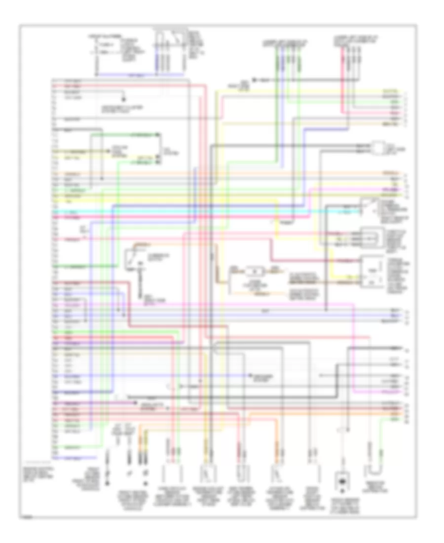
1.6L, Engine Performance Wiring Diagrams (1 of 2) for Nissan 200SX SE-R 1995
 https://portal-diagnostov.com/license.html
Automotive Electricians Portal FZCO
Automotive Electricians Portal FZCO
https://portal-diagnostov.com/license.html
https://portal-diagnostov.com/license.html
Automotive Electricians Portal FZCO
Automotive Electricians Portal FZCO
List of elements for 1.6L, Engine Performance Wiring Diagrams (1 of 2) for Nissan 200SX SE-R 1995:
- (under left side of i/p) data link connector
- (under left side of i/p) data link connector for gst
- 7.5a
- A/c system
- A/t only
- Calif & a/t
- Cooling fans system
- Crank- shaft position sensor (below distributor)
- Defogger system
- Diode (top center of i/p)
- Eccs relay (below center of i/p, next to ecm)
- Egr temper- ature sensor (left rear of eng, below egr valve)
- Engine control module (ecm) (below center of i/p)
- Engine coolant temperature sensor (right rear of eng)
- Front heated oxygen sensor (front of eng, on exhaust manifold)
- Front oxygen sensor (front of eng, on exhaust manifold)
- Fuse 41
- Fusible link & fuse box (left front of eng compt)
- G201 (right side of i/p)
- Headlights system
- Hot at all times
- Instrument cluster system (tach)
- Intake air temperature sensor (mounted into air cleaner assembly)
- J/c 4 (left side of i/p)
- Knock sensor (attached to top center of cylinder head)
- M/t m/t non- calif
- Mass air flow sensor (between intake manifold and air cleaner assembly)
- Nca
- Off
- Overdrive switch
- Pnk
- Power steering oil pressure switch (right rear of eng compt)
- Red
- Resistor (behind distributor)
- Tcc
- Throttle position sensor (side of throttle body)
- Torque converter clutch/ overdrive cancel solenoid valves (on trans- mission)
- W/ automatic speed control device (ascd)
- W/o automatic speed control device (ascd)
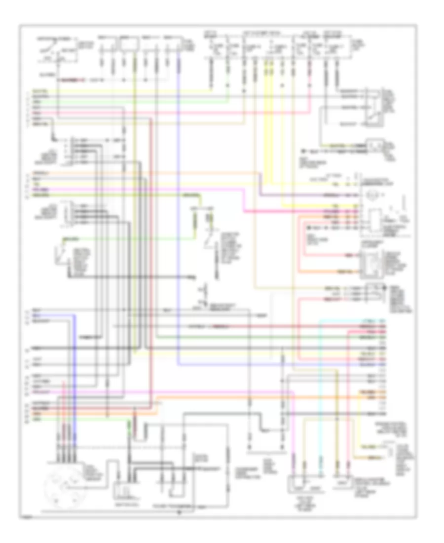
1.6L, Engine Performance Wiring Diagrams (2 of 2) for Nissan 200SX SE-R 1995
 https://portal-diagnostov.com/license.html
Automotive Electricians Portal FZCO
Automotive Electricians Portal FZCO
https://portal-diagnostov.com/license.html
https://portal-diagnostov.com/license.html
Automotive Electricians Portal FZCO
Automotive Electricians Portal FZCOList of elements for 1.6L, Engine Performance Wiring Diagrams (2 of 2) for Nissan 200SX SE-R 1995:
- (behind right headlamp)
- 10l
- 13n
- 16n
- 19k
- 1o1
- A/t
- Acc
- All times
- Cam- shaft position sensor
- Condenser (near distributor)
- Distri- butor
- Egr & canister control solenoid valve (left rear of eng)
- Electronic speedo- meter
- Engine control module (ecm) (below center of i/p)
- Fuel injec- tors
- Fuel pump (in fuel tank)
- Fuel pump relay (left side of i/p)
- Fuse 10a
- Fuse 16 10a
- Fuse 17 15a
- Fuse 7.5a
- Fuse 8 10a
- Fuse block (i/p)
- G107
- G120 (right side of eng)
- G201 (right side of i/p)
- G407 (center rear of trunk)
- Hot at
- Hot at all times
- Hot in on or start
- Hot in start
- Hot in start or on
- Iacv-acc valve (left rear of eng)
- Ignition coil
- Ignition switch
- Inhibitor switch (closed in park or neutral) (on top of trans- axle)
- Instrument cluster
- J/c 1 (center rear of eng compt)
- J/c 2 (center rear of eng compt)
- M/t
- Malfunction indicator lamp
- Nca
- Neutral position switch (right side of trans- axle)
- No.1
- No.2
- No.3
- No.4
- Off
- Pnk
- Power transistor
- Rear heated oxygen sensor (behind catalytic converter)
- Red
- Start
- Valve timing control solenoid (top right side of eng)
- Vehicle speed sensor (right side of trans- axle)
- W/ tach
- W/o tach
2.0L
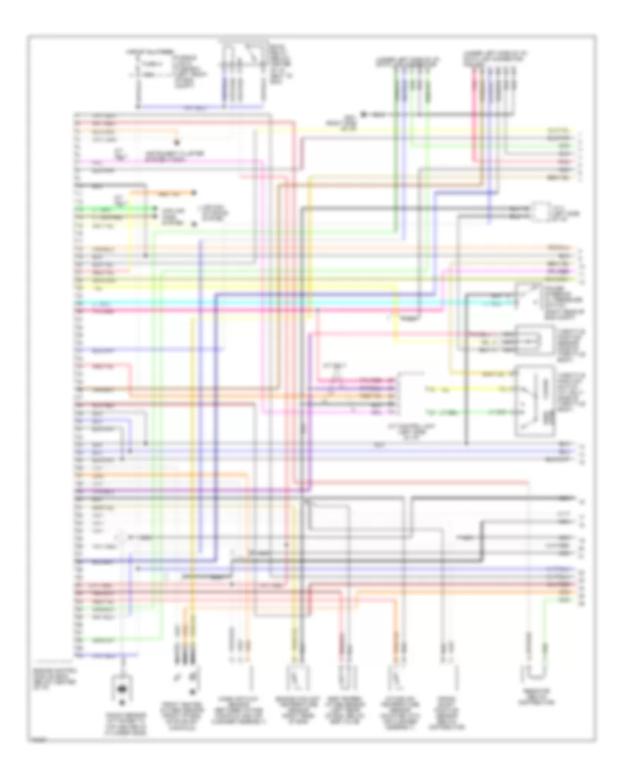
2.0L, Engine Performance Wiring Diagrams (1 of 2) for Nissan 200SX SE-R 1995
 https://portal-diagnostov.com/license.html
Automotive Electricians Portal FZCO
Automotive Electricians Portal FZCO
https://portal-diagnostov.com/license.html
https://portal-diagnostov.com/license.html
Automotive Electricians Portal FZCO
Automotive Electricians Portal FZCOList of elements for 2.0L, Engine Performance Wiring Diagrams (1 of 2) for Nissan 200SX SE-R 1995:
- (under left side of i/p) data link connector
- (under left side of i/p) data link connector for gst
- 7.5a
- A/t control unit (left side of i/p)
- A/t only
- Air con- ditioning system
- Closed
- Cooling fans system
- Crank- shaft position sensor (below distributor)
- Eccs relay (below center of i/p, next to ecm)
- Egr temper- ature sensor (left rear of eng, below egr valve)
- Engine control module (ecm) (below center of i/p)
- Engine coolant temperature sensor (right rear of eng)
- Front heated oxygen sensor (front of eng, on exhaust manifold)
- Fuse 41
- Fusible link & fuse box (left front of eng compt)
- G201 (right side of i/p)
- Hot at all times
- Instrument cluster system (tach)
- Intake air temperature sensor (mounted into air cleaner assembly)
- J/c 4 (left side of i/p)
- Knock sensor (attached to top center of cylinder head)
- Mass air flow sensor (between intake manifold and air cleaner assembly)
- Nca
- Open wide
- Pnk
- Power steering oil pressure switch (right rear of eng compt)
- Resistor (below distributor)
- Throttle position sensor (side of throttle body)
- Throttle position switch (a/t only) (side of throttle body)
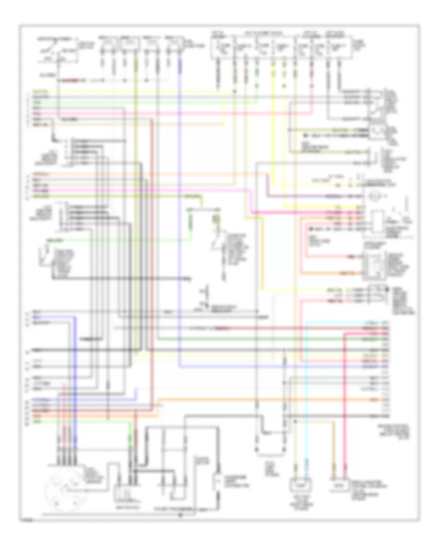
2.0L, Engine Performance Wiring Diagrams (2 of 2) for Nissan 200SX SE-R 1995
 https://portal-diagnostov.com/license.html
Automotive Electricians Portal FZCO
Automotive Electricians Portal FZCO
https://portal-diagnostov.com/license.html
https://portal-diagnostov.com/license.html
Automotive Electricians Portal FZCO
Automotive Electricians Portal FZCOList of elements for 2.0L, Engine Performance Wiring Diagrams (2 of 2) for Nissan 200SX SE-R 1995:
- (behind right headlamp)
- 10l
- 13n
- 16n
- 19k
- 1o1
- A/t
- Acc
- Cam- shaft position sensor
- Condenser (near distributor)
- Distri- butor
- Egr & canister control solenoid valve (center rear of eng)
- Electronic speedo- meter
- Engine control module (ecm) (below center of i/p)
- Fuel injectors
- Fuel pump (in fuel tank)
- Fuel pump relay (left side of i/p)
- Fuse 10a
- Fuse 16 10a
- Fuse 17 15a
- Fuse 7.5a
- Fuse 8 10a
- Fuse block (i/p)
- G107
- G112 (left side of eng)
- G201 (right side of i/p)
- G407 (center rear of trunk)
- Hot at all times
- Hot in on or start
- Hot in start
- Hot in start or on
- Iacv- air regulator (right rear of eng)
- Iacv-acc valve (right rear of eng)
- Ignition coil
- Ignition switch
- Inhibitor switch (closed in park or neutral) (on top of trans- axle)
- Instrument cluster
- J/c 1 (center rear of eng compt)
- J/c 2 (center rear of eng compt)
- M/t
- Malfunction indicator lamp
- Nca
- Neutral position switch (right side of trans- axle)
- No.1
- No.2
- No.3
- No.4
- Off
- Pnk
- Power transistor
- Rear heated oxygen sensor (behind catalytic converter)
- Red
- Start
- Vehicle speed sensor (right side of trans- mission)
- W/ tach
- W/o tach

 Čeština
 Dansk
Dansk Deutsch
 Ελληνικά
 English
 English
 Español
 Suomi
Suomi Français
 Français
 עברית
עברית Hrvatski
 Magyar
 Italiano
 日本語
日本語 한국어
한국어 Nederlands
 Polski
 Português
 Português
 Română
 Русский
 Slovenčina
 Slovenščina
 Svenska
 Türkçe
