TRANSMISSION
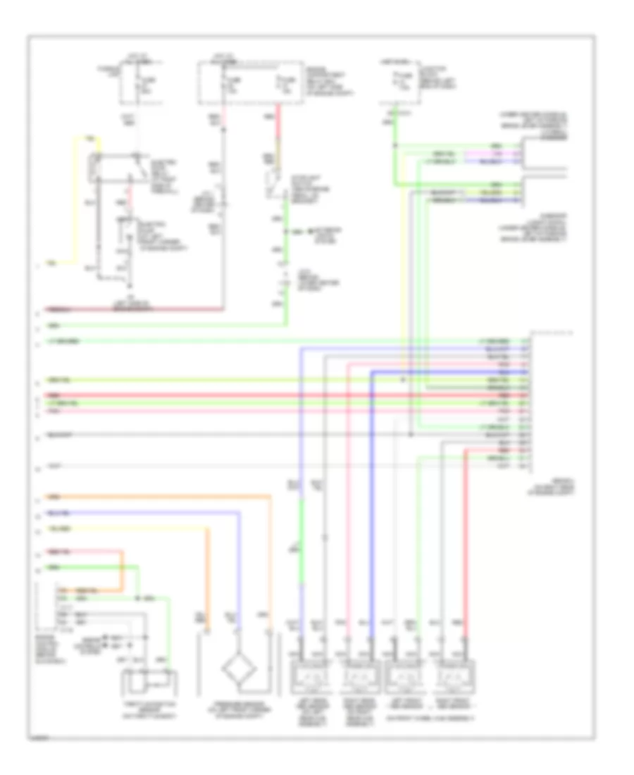
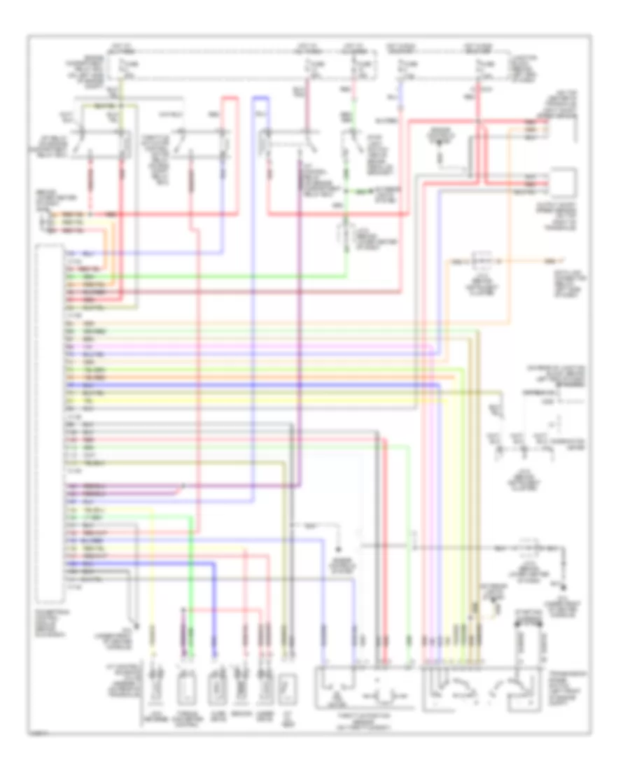
4WD Wiring Diagram, Evolution with ABS (1 of 2) for Mitsubishi Lancer O-Z Rally 2006
 https://portal-diagnostov.com/license.html
Automotive Electricians Portal FZCO
Automotive Electricians Portal FZCO
https://portal-diagnostov.com/license.html
https://portal-diagnostov.com/license.html
Automotive Electricians Portal FZCO
Automotive Electricians Portal FZCO
List of elements for 4WD Wiring Diagram, Evolution with ABS (1 of 2) for Mitsubishi Lancer O-Z Rally 2006:
- (on left front corner of engine compt) proportioning valve
- Acd mode changeover switch
- Anti-lock brakes system
- Awd-ecu (behind lower right side of dash)
- C138
- C139
- C210
- C214
- Combination meter
- Computer data lines system
- Drive circuit
- Fuse 7.5a
- G3 (at right side of front deck crossmember)
- G4 (left side of engine compt)
- Gravel ind
- Hot in on
- Hot in on or start
- Ill
- Interior lights system
- J/c 2 (behind instrument cluster)
- J/c 3 (behind right side of dash)
- J/c 4
- J/c 6 (behind lower center of dash)
- Junction block (behind left end of dash)
- Nca
- Parking brake switch (at base of parking brake lever)
- Pnk
- Red
- Snow ind
- Steering angular velocity sensor (at top of steering column)
- Tarmac ind
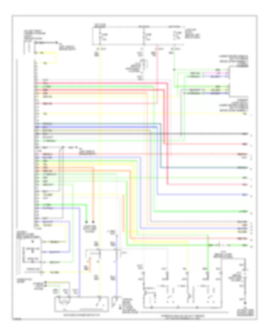
4WD Wiring Diagram, Evolution with ABS (2 of 2) for Mitsubishi Lancer O-Z Rally 2006
 https://portal-diagnostov.com/license.html
Automotive Electricians Portal FZCO
Automotive Electricians Portal FZCO
https://portal-diagnostov.com/license.html
https://portal-diagnostov.com/license.html
Automotive Electricians Portal FZCO
Automotive Electricians Portal FZCOList of elements for 4WD Wiring Diagram, Evolution with ABS (2 of 2) for Mitsubishi Lancer O-Z Rally 2006:
- (left side of engine compt)
- (on front wheel hub assembly)
- (under center console, left of parking brake lever assembly) (lateral) g-sensor
- Abs-ecu (on right rear of engine compt)
- C-214
- C117
- C119
- Electric pump (at left front corner of engine compt)
- Electric pump relay (at right side of firewall)
- Engine compartment relay box (on left side of engine compt)
- Engine control module (behind glove box)
- Engine controls system
- Exterior lights system
- Fuse 10a
- Fuse 15a
- Fuse 60a
- Fuse 7.5a
- Fusible link
- G-sensor (longitudinal) (under center console, left of parking brake lever assembly)
- Hot at all times
- Hot in on
- J/c 1 (behind center of dash)
- J/c 6 (behind lower center of dash)
- Junction block (behind left end of dash)
- Left front abs sensor
- Left rear abs sensor (on left rear hub assembly)
- Nca
- Pnk
- Pressure sensor (on left front corner of engine compt)
- Red
- Right front abs sensor
- Right rear abs sensor (on right rear hub assembly)
- Stoplight switch (above brake pedal, on bracket)
- Throttle position sensor (on throttle body)
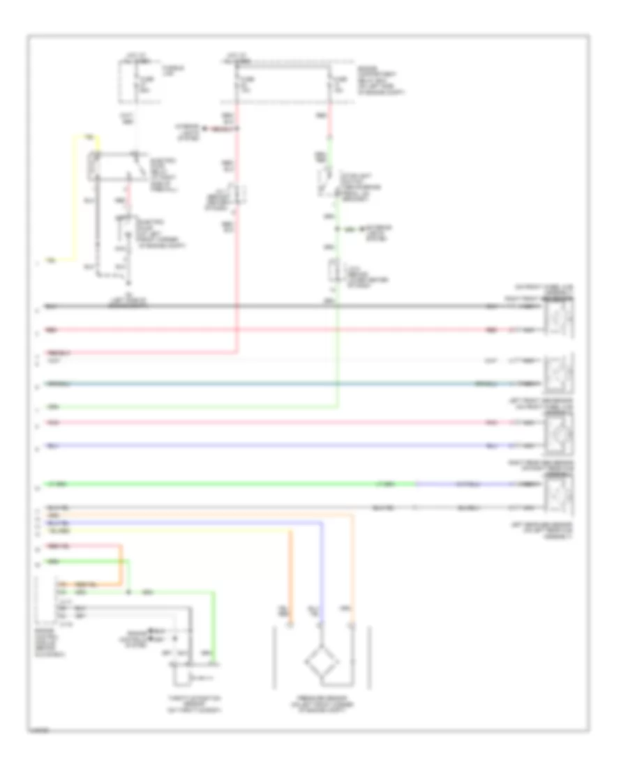
4WD Wiring Diagram, Evolution without ABS (1 of 2) for Mitsubishi Lancer O-Z Rally 2006
 https://portal-diagnostov.com/license.html
Automotive Electricians Portal FZCO
Automotive Electricians Portal FZCO
https://portal-diagnostov.com/license.html
https://portal-diagnostov.com/license.html
Automotive Electricians Portal FZCO
Automotive Electricians Portal FZCOList of elements for 4WD Wiring Diagram, Evolution without ABS (1 of 2) for Mitsubishi Lancer O-Z Rally 2006:
- (on left front corner of engine compt) proportioning valve
- (under center console, left of parking brake lever assembly) (lateral) g-sensor
- Acd mode changeover switch
- Awd-ecu (behind lower right side of dash)
- C138
- C139
- C210
- C214
- Combination meter
- Computer data lines system
- Drive circuit
- Fuse 7.5a
- G-sensor (longitudinal) (under center console, left of parking brake lever assembly)
- G3 (at right side of front deck crossmember)
- G4 (left side of engine compt)
- Gravel ind
- Hot in on
- Hot in on or start
- Ill
- Interior lights system
- J/c 2 (behind instrument cluster)
- J/c 3 (behind right side of dash)
- J/c 4
- J/c 6 (behind lower center of dash)
- Junction block (behind left end of dash)
- Nca
- Parking brake switch (at base of parking brake lever)
- Pnk
- Red
- Snow ind
- Steering angular velocity sensor (at top of steering column)
- Tarmac ind
4WD Wiring Diagram, Evolution without ABS (2 of 2) for Mitsubishi Lancer O-Z Rally 2006
 https://portal-diagnostov.com/license.html
Automotive Electricians Portal FZCO
Automotive Electricians Portal FZCO
https://portal-diagnostov.com/license.html
https://portal-diagnostov.com/license.html
Automotive Electricians Portal FZCO
Automotive Electricians Portal FZCOList of elements for 4WD Wiring Diagram, Evolution without ABS (2 of 2) for Mitsubishi Lancer O-Z Rally 2006:
- (on front wheel hub assembly) right front abs sensor
- C117
- C119
- Electric pump (at left front corner of engine compt)
- Electric pump relay (at right side of firewall)
- Engine compartment relay box (on left side of engine compt)
- Engine control module (behind glove box)
- Engine controls system
- Exterior lights system
- Fuse 10a
- Fuse 15a
- Fuse 60a
- Fusible link
- G4 (left side of engine compt)
- Hot at all times
- Interior lights system
- J/c 1 (behind center of dash)
- J/c 6 (behind lower center of dash)
- Left front abs sensor (on front wheel hub assembly)
- Left rear abs sensor (on left rear hub assembly)
- Nca
- Pnk
- Pressure sensor (on left front corner of engine compt)
- Red
- Right rear abs sensor (on right rear hub assembly)
- Stoplight switch (above brake pedal, on bracket)
- Throttle position sensor (on throttle body)
2.0L
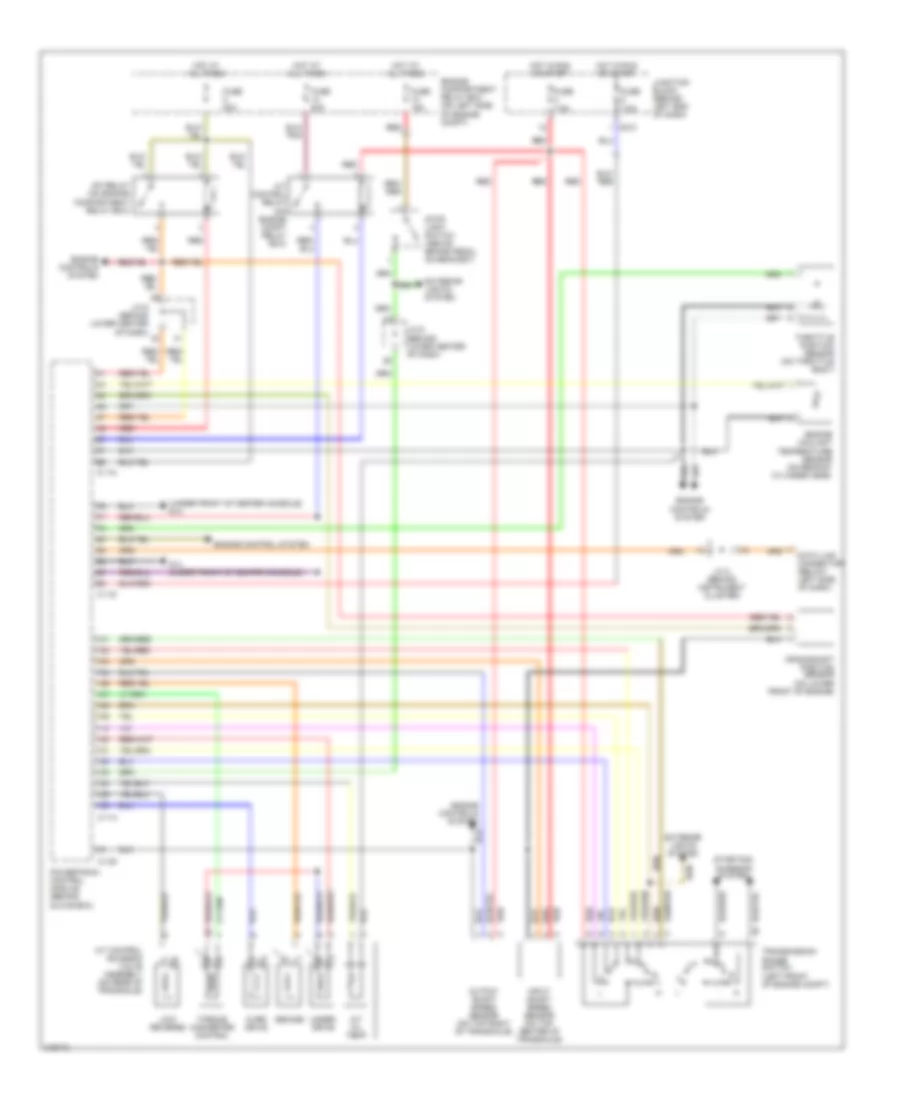
2.0L, A/T Wiring Diagram for Mitsubishi Lancer O-Z Rally 2006
 https://portal-diagnostov.com/license.html
Automotive Electricians Portal FZCO
Automotive Electricians Portal FZCO
https://portal-diagnostov.com/license.html
https://portal-diagnostov.com/license.html
Automotive Electricians Portal FZCO
Automotive Electricians Portal FZCOList of elements for 2.0L, A/T Wiring Diagram for Mitsubishi Lancer O-Z Rally 2006:
- (under front of center console) g14
- A/t control relay (on engine compt relay box)
- A/t control solenoid valve assembly (on rear of transaxle)
- A/t oil temp
- C-114
- C-116
- C-118
- C-120
- C210
- Crankshaft position sensor (on lower front of engine)
- Data link connector (below left side of dash)
- Engine compartment relay box (on left side of engine compt)
- Engine control system
- Engine controls system
- Engine coolant temperature sensor (on rear of cylinder head)
- Exterior lights system
- Fuse 15a
- Fuse 20a
- Fuse 7.5a
- G14 (under front of center console)
- Hot at all times
- Hot in run or start
- Input shaft speed sensor (on top center of transaxle)
- J/c 2 (behind instrument cluster)
- J/c 6 (behind lower center of dash)
- Junction block (behind left end of dash)
- Low/ reverse
- Mfi relay (on engine compartment relay box)
- Output shaft speed sensor (on top right of transaxle)
- Over drive
- Powertrain control module (behind glove box)
- Red
- Second
- Starting/ charging system
- Stop light switch (above brake pedal, on bracket)
- Throttle position sensor (on throttle body)
- Torque converter control
- Transmission range switch (left front of engine compt)
- Under drive
2.4L
2.4L, A/T Wiring Diagram for Mitsubishi Lancer O-Z Rally 2006
 https://portal-diagnostov.com/license.html
Automotive Electricians Portal FZCO
Automotive Electricians Portal FZCO
https://portal-diagnostov.com/license.html
https://portal-diagnostov.com/license.html
Automotive Electricians Portal FZCO
Automotive Electricians Portal FZCOList of elements for 2.4L, A/T Wiring Diagram for Mitsubishi Lancer O-Z Rally 2006:
- (behind lower center of dash) j/c 6
- (on rear of junction block, behind left end of dash) etacs ecu
- (on top center of transaxle) input shaft speed sensor
- A/t control relay (on engine compartment relay box)
- A/t control solenoid valve assembly (on rear of transaxle)
- A/t oil temp
- C-134
- C-136
- C-138
- C-140
- C-142
- C210
- C228
- Combination meter
- Data link connector (below left side of dash)
- Engine compartment relay box (on left side of engine compt)
- Engine controls system
- Exterior lights system
- Fuse 15a
- Fuse 20a
- Fuse 7.5a
- G14 (under front of center console)
- Hot at all times
- Hot in run or start
- J/c 2 (behind instrument cluster)
- J/c 5 (behind instrument cluster)
- J/c 6 (behind lower center of dash)
- Junction block (behind left end of dash)
- Low/ reverse
- Mfi relay (on engine compartment relay box)
- Output shaft speed sensor (on top right of transaxle)
- Over drive
- Powertrain control module (behind glove box)
- Red
- Second
- Starting/ charging system
- Stop light switch (above brake pedal,on bracket)
- Tac motor
- Throttle actuator control motor relay (on eng compt relay box)
- Throttle position sensor (on throttle body)
- Torque converter control
- Transmission range switch (left front of engine compt)
- Under drive

 Čeština
 Dansk
Dansk Deutsch
 Ελληνικά
 English
 English
 Español
 Suomi
Suomi Français
 Français
 עברית
עברית Hrvatski
 Magyar
 Italiano
 日本語
日本語 한국어
한국어 Nederlands
 Polski
 Português
 Português
 Română
 Русский
 Slovenčina
 Slovenščina
 Svenska
 Türkçe
