ANTI-LOCK BRAKES
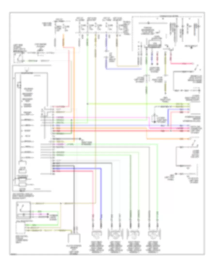
Anti-lock Brakes Wiring Diagram for Subaru Legacy GT Limited 2010
 https://portal-diagnostov.com/license.html
Automotive Electricians Portal FZCO
Automotive Electricians Portal FZCO
https://portal-diagnostov.com/license.html
https://portal-diagnostov.com/license.html
Automotive Electricians Portal FZCO
Automotive Electricians Portal FZCO
List of elements for Anti-lock Brakes Wiring Diagram for Subaru Legacy GT Limited 2010:
- (left side of dash) stop light & brake switch
- (top center of dash) j/c b512
- Abs warning light
- B152
- B158
- Brake fluid level switch (brake master cylinder)
- Can transceiver & receiver
- Clutch stroke sensor (m/t) (left side of dash)
- Combination meter
- Computer data lines system
- Data link connector (left end of dash)
- Drive circuit
- Epb control module (under rear seat)
- Fl in
- Fl out
- Fr in
- Fr out
- Fuse & relay box (f/b) (left kick panel)
- Fuse 15a
- Fuse 30a
- Fuse 7.5a
- Gb-5 (right kick panel)
- Gb-6 (left kick panel)
- Gv (right side of engine)
- Hill hold switch
- Hot at all times
- Hot in on or start
- I/f
- I152
- I82
- I83
- Interior lights system
- J/c b483 (right front of engine compt)
- J/c b491 (left end of dash)
- J/c i165 (left side of dash)
- J/c i82 & i83 (left end of dash)
- J/c i82 (left end of dash)
- J/c i98 (right side of dash)
- Left front abs wheel speed sensor (left front wheel spindle assembly)
- Left rear abs wheel speed sensor (left rear wheel spindle assembly)
- Lower cover switch (vdc off)
- Main fuse box (m/b)
- Micro computer
- Motor relay
- Nca
- On ind hill hold
- Parking brake/brake fluid level warning light
- Pnk
- Primary cut
- Primary suction
- Pump motor
- Red
- Right front abs wheel speed sensor (right front wheel spindle assembly)
- Right rear abs wheel speed sensor (right rear wheel spindle assembly)
- Rl in
- Rl out
- Rr in
- Rr out
- Sbf-6 fuse 40a
- Secondary cut
- Secondary suction
- Solenoid valve
- Steering angle sensor (steering column)
- Valve relay
- Vdc control module (right rear corner of engine compt)
- Vdc off ind
- Vdc warning light/ vdc operation ind light
- Yaw rate & g sensor
 Čeština
 Dansk
Dansk Deutsch
 Ελληνικά
 English
 English
 Español
 Suomi
Suomi Français
 Français
 עברית
עברית Hrvatski
 Magyar
 Italiano
 日本語
日本語 한국어
한국어 Nederlands
 Polski
 Português
 Português
 Română
 Русский
 Slovenčina
 Slovenščina
 Svenska
 Türkçe
 中文 (中国)
