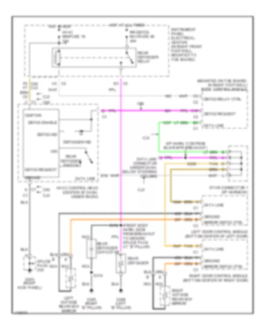
DEFOGGERS
Defogger Wiring Diagram for Chevrolet Corvette 1999
 https://portal-diagnostov.com/license.html
Automotive Electricians Portal FZCO
Automotive Electricians Portal FZCO
https://portal-diagnostov.com/license.html
https://portal-diagnostov.com/license.html
Automotive Electricians Portal FZCO
Automotive Electricians Portal FZCO
List of elements for Defogger Wiring Diagram for Chevrolet Corvette 1999:
- (front body harn, 20cm from breakout to ground splice pack at "b" pillar)
- (i/p harn, 5 cm from blwr mtr breakout)
- (mounted on toe board, in right footwell) body control module
- C1 c
- C1 k
- C10
- C2 a5
- C60
- Cj2
- D12
- Data line
- Data link connector (under dash, below steering column)
- Defog enable
- Defog ind
- Defog relay ctrl
- Defog request
- Defogger ind
- E5 c3
- F6 c60 cj2 f7
- G203 (right kick panel)
- G305 (right "b" pillar)
- G308 (left "b" pillar)
- Ground
- Hot at all times
- Hot in run
- Hvac control head (center of dash, under radio)
- Hvac minifuse 18 10a
- Ign
- Ignition
- Instrument panel electrical center (in right front footwell, mounted to toe board)
- Left door control module (bottom center of left door)
- Left outside rearview mirror
- Mirror defog ctrl
- Nca
- Rear defogger
- Rear defogger capacitor
- Rear defogger relay
- Rear defogger switch
- Right door control module (bottom center of right door)
- Right outside rearview mirror
- Rr defog maxifuse 48 40a
- S206
- S312
- S314
- Splice pack
- Star connector 1 (i/p harness)
- Tan
 Čeština
 Dansk
Dansk Deutsch
 Ελληνικά
 English
 English
 Español
 Suomi
Suomi Français
 Français
 עברית
עברית Hrvatski
 Magyar
 Italiano
 日本語
日本語 한국어
한국어 Nederlands
 Polski
 Português
 Português
 Română
 Русский
 Slovenčina
 Slovenščina
 Svenska
 Türkçe
 中文 (中国)
