ENGINE PERFORMANCE
5.7L
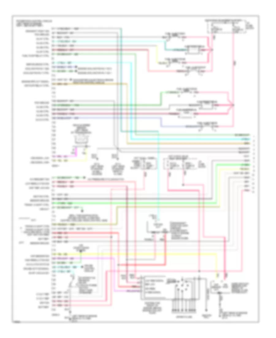
5.7L (VIN 5), Engine Performance Wiring Diagrams (1 of 3) for Chevrolet Corvette 1996
 https://portal-diagnostov.com/license.html
Automotive Electricians Portal FZCO
Automotive Electricians Portal FZCO
https://portal-diagnostov.com/license.html
https://portal-diagnostov.com/license.html
Automotive Electricians Portal FZCO
Automotive Electricians Portal FZCO
List of elements for 5.7L (VIN 5), Engine Performance Wiring Diagrams (1 of 3) for Chevrolet Corvette 1996:
- (a/t)
- (left rear of engine near oil filter) g114
- (m/t)
- 324
- 5 volt ref
- 687
- A/c clutch status
- A/c pressure cycling switch
- A/c request sig
- Air conditioning system
- Air pump relay ctrl
- Battery
- Ckp sig out
- Coil wire
- Conn 1
- Conn 2
- Cooling fan rly 2&3
- Cooling fan rly ctrl
- Crankshaft position (ckp) sensor (lower right side of engine, in front engine cover)
- Crnkshft posit sig
- Cruise active signal
- Cruise control module
- Dist ref low sig
- Distributor (front of engine, behind engine coolant pump)
- E.c.m. fuse 33 5a
- Ecm fuse 1 20a
- Egr solenoid ctrl
- Eng 1 fuse 30 10a
- Engine cooling fan rly no.1
- Engine cooling fan rly no.3
- Engine spd out signal
- Evap vacuum sw
- Evaporative emission (evap) vacuum purge switch (right side of engine)
- Fuel injector #1
- Fuel injector #2
- Fuel injector #3
- Fuel injector #4
- Fuel injector #5
- Fuel injector #6
- Fuel injector #7
- Fuel injector #8
- Fuel pump relay ctrl
- G114 (left rear of engine, near oil filter)
- G114 (left rear of engine, on bell housing)
- Gnd
- Hi res signal
- High resolution sig
- Hot at all times
- Hot in run, bulb test & start
- Hot in run, bulb test or start
- I/p fuse block
- Ign feed
- Ign pwr
- Ignition
- Ignition coil
- Ignition ctrl
- Inj # 8 ctrl
- Inj #1 ctrl
- Inj #2 ctrl
- Inj #3 ctrl
- Inj #4 ctrl
- Inj #5 ctrl
- Inj #6 ctrl
- Inj #7 ctrl
- Inj 1 fuse 22 10a
- Inj 2 fuse 23 10a
- Low res signal
- Low resolution sig
- Maf sensor out
- Maf sensor sig
- Mass air flow sensor (maf) (front of engine, in air intake duct)
- Optical sensor
- Pcm ground
- Pnk
- Pnk c
- Powertrain control module (left rear of engine cmpt, above battery)
- Real time damping (rtd), cruise control & central control modules, radio control head
- Red
- Ref lo
- Ref low
- Sensor ground
- Spark plugs
- Tachometer & electronic brake/ traction control module
- Trans 1-2 shift ctrl
- Trans 2-3 shift ctrl
- Trans 3-2 shift ctrl 2nd & 3rd gr rly ctrl dist ignition feed
- Under- hood fuse block 1
- Vehicle speed sensor (left rear of transmission)
- Vss out
- Vss signal high
- Vss signal low
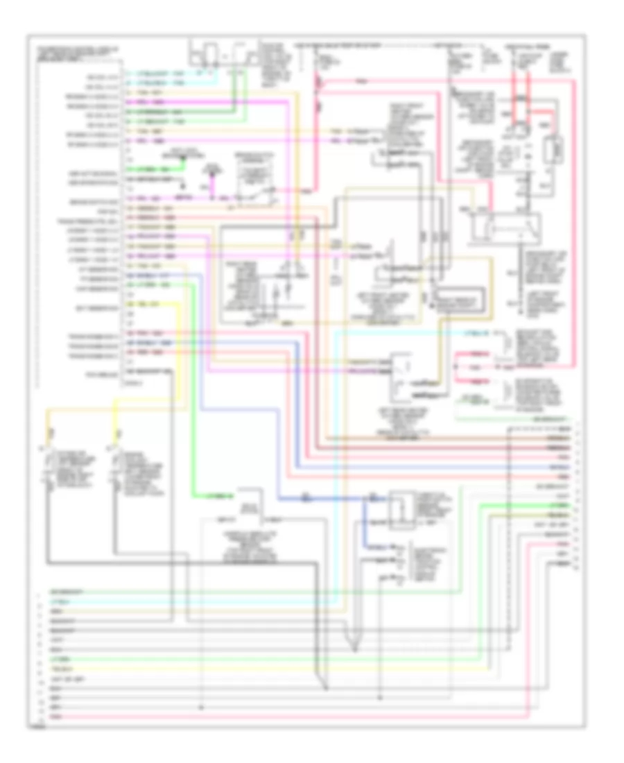
5.7L (VIN 5), Engine Performance Wiring Diagrams (2 of 3) for Chevrolet Corvette 1996
 https://portal-diagnostov.com/license.html
Automotive Electricians Portal FZCO
Automotive Electricians Portal FZCO
https://portal-diagnostov.com/license.html
https://portal-diagnostov.com/license.html
Automotive Electricians Portal FZCO
Automotive Electricians Portal FZCOList of elements for 5.7L (VIN 5), Engine Performance Wiring Diagrams (2 of 3) for Chevrolet Corvette 1996:
- (left front of engine compartment, near horn) g100
- (right rear of engine compt.) g103
- Air pump fuse 8 20a
- Anti-lock brakes system
- Asr active signal
- Asr spark rtd sig
- Brake switch assembly
- Brake switch sig
- Btsi system
- Coil a
- Coil b
- Conn 3
- Ebtcm
- Ect sensor sig
- Electronic brake/ traction control module (ebtcm)
- Eng 1 fuse 30 10a
- Engine coolant temperature (ect) sensor (lower front of engine, mounted to coolant pump)
- Evaporative emission (evap) canister purge solenoid valve (top right front of engine)
- Exhaust gas recirculation (egr) vacuum control signal solenoid valve (top left rear of engine)
- Hot at all times
- Hot in run
- Hot in run, bulb test or start
- I/p fuse block
- Iac coil a hi
- Iac coil a lo
- Iac coil b hi
- Iac coil b lo
- Iat sensor sig
- Idle air control (iac) valve (top right front of engine, on throttle body)
- Int. stop valve sol.
- Intake air temperature (iat) sensor (front of engine, right side of air intake duct)
- Left front heated oxygen sensor (ho2s) no.1 (bank 1) (forward of catalytic converter)
- Left rear heated oxygen sensor (ho2s) no.2 (bank 1) (rear of catalytic converter)
- Lf bank 1 ho2s 1 hi
- Lf bank 1 ho2s 1 lo
- Lr bank 1 ho2s 2 hi
- Lr bank 1 ho2s 2 lo
- Manifold absolute pressure (map) sensor (top right front of engine, mounted to intake manifold)
- Map sensor sig
- Nca
- Oxygen sen fuse 20 15a
- Pcm ground
- Pin
- Pnk
- Pnp sw
- Powertrain control module (left rear of engine cmpt, above battery)
- Red
- Rf bank 2 ho2s 2 hi
- Rf bank 2 ho2s 2 lo
- Right front heated oxygen sensor (ho2s) no.1 bank 2 (forward of catalytic converter)
- Right rear heated oxygen sensor (ho2s) no.2 (bank 2) (rear of catalytic converter)
- Rr bank 2 ho2s 2 hi
- Rr bank 2 ho2s 2 lo
- Secondary air injection (air) bleed valve solenoid (attached to air pump)
- Secondary air injection (air) pump (left front of engine compt. behind horn)
- Secondary air injection (air) pump relay (left front of engine compt. behind horn)
- Solid state
- Tan
- Tan b
- Tcc/shift interrupt switch
- Throttle position (tp) sensor (right front of engine)
- Tp sensor sig
- Trans press ctrl sol
- Trans range sig a
- Trans range sig b
- Trans range sig c
- Under- hood fuse block 2
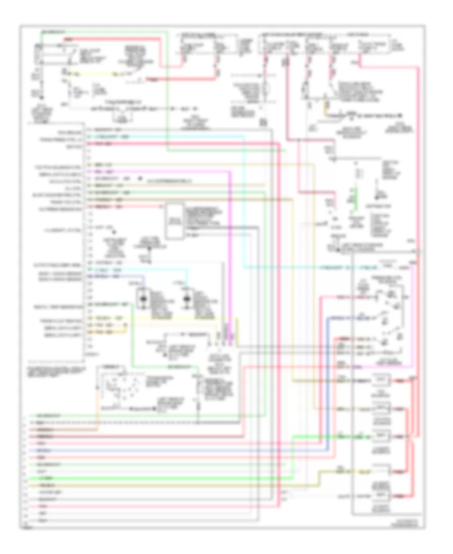
5.7L (VIN 5), Engine Performance Wiring Diagrams (3 of 3) for Chevrolet Corvette 1996
 https://portal-diagnostov.com/license.html
Automotive Electricians Portal FZCO
Automotive Electricians Portal FZCO
https://portal-diagnostov.com/license.html
https://portal-diagnostov.com/license.html
Automotive Electricians Portal FZCO
Automotive Electricians Portal FZCOList of elements for 5.7L (VIN 5), Engine Performance Wiring Diagrams (3 of 3) for Chevrolet Corvette 1996:
- (left rear of engine near oil filter) g114
- (left rear of engine on bell housing) g114
- (right rear engine compt)
- 1-2 shift solenoid
- 1-4 upshift lp ctrl
- 2-3 shift solenoid
- 2nd & 3rd gear blockout relay (right side of engine compartment, on inner wheelhouse)
- 2nd & 3rd gear blockout solenoid
- 3-2 shift solenoid
- A/c clutch ctrl
- A/c compressor relay
- A/c press sensor sig
- A/c refrigerant pressure sensor (near blower motor, in a/c high press. pipe)
- A/t
- A/t fluid press sw
- A/t fluid temp sensor
- Auto trans fuse 15 10a
- Automatic transmission
- Back-up fuse 28 15a
- Bank 1 knock sensor
- Bank 2 knock sensor
- C red
- Cluster fuse 27 5a
- Coil fuse 10a
- Coil wire
- Conn 4
- D2 sw
- D3 sw
- D4 sw
- Data link connector (dlc) (below left side of i/p)
- Distributor
- Driver information center (dic)
- Ecm fuse 1 20a
- Eng 1 fuse 30 10a
- Eng oil temp sensor sig
- Engine oil pressure/ fuel pump switch (closed w/engine running)
- Engine oil temperature (eot) sensor (left rear of engine, above oil filter)
- Evap canister prg ctrl
- Fp 1 fuse 14 10a
- Fuel pump
- Fuel pump fuse 2 20a
- Fuel pump module
- Fuel pump relay (below right side of i/p)
- G103
- G114 (left rear of engine, near oil filter)
- G401 (right front of cargo compartment)
- Ground
- Hot at all times
- Hot in run
- Hot in run, bulb test & start
- I/p fuse block
- Ic sig
- Ign
- Ignition
- Ignition coil (right front of engine)
- Ignition coil module (right front of engine)
- Instrument cluster (one - to-four indicator)
- Left knock sensor (ks) (bank 1) (bottom left side of engine)
- Lo sw
- Low tire pressure warning module
- M/t
- M/t only
- Malfunction indicator (service engine soon)
- Mil ctrl
- Nca
- Output/field serv enbl
- Pcm ground
- Pnk
- Pnk c
- Powertrain control module (left rear of engine compt, above battery)
- Pressure ctrl. solenoid
- Primary coil driver
- Red
- Red a
- Rev sw
- Right knock sensor (ks) (bank 2) (bottom right side of engine)
- Serial data (class 2)
- Serial data (uart)
- Solid state
- Tan
- Tan b
- Tcc pwm solenoid
- Tcc pwm solenoid ctrl
- Tcc solenoid
- Trans fluid temp sig
- Trans press ctrl lo
- Trans tcc ctrl
- Transmission range (tr) switch
- Under- hood fuse block #1
5.7L (VIN P), Engine Performance Wiring Diagrams (1 of 3) for Chevrolet Corvette 1996
 https://portal-diagnostov.com/license.html
Automotive Electricians Portal FZCO
Automotive Electricians Portal FZCO
https://portal-diagnostov.com/license.html
https://portal-diagnostov.com/license.html
Automotive Electricians Portal FZCO
Automotive Electricians Portal FZCOList of elements for 5.7L (VIN P), Engine Performance Wiring Diagrams (1 of 3) for Chevrolet Corvette 1996:
- (a/t)
- (left rear of engine near oil filter) g114
- (m/t)
- 324
- 5 volt ref
- 687
- A/c clutch status
- A/c pressure cycling switch
- A/c request sig
- Air conditioning system
- Air pump relay ctrl
- Battery
- Ckp sig out
- Coil wire
- Conn 1
- Conn 2
- Cooling fan rly 2&3
- Cooling fan rly ctrl
- Crankshaft position (ckp) sensor (lower right side of engine, in front engine cover)
- Crnkshft posit sig
- Cruise active signal
- Cruise control module
- Dist ref low sig
- Distributor (front of engine, behind engine coolant pump)
- E.c.m. fuse 33 5a
- Ecm fuse 1 20a
- Egr solenoid ctrl
- Eng 1 fuse 30 10a
- Engine cooling fan rly no.1
- Engine cooling fan rly no.3
- Engine spd out signal
- Evap vacuum sw
- Evaporative emission (evap) vacuum purge switch (right side of engine)
- Fuel injector #1
- Fuel injector #2
- Fuel injector #3
- Fuel injector #4
- Fuel injector #5
- Fuel injector #6
- Fuel injector #7
- Fuel injector #8
- Fuel pump relay ctrl
- G114 (left rear of engine, near oil filter)
- G114 (left rear of engine, on bell housing)
- Gnd
- Hi res signal
- High resolution sig
- Hot at all times
- Hot in run, bulb test & start
- Hot in run, bulb test or start
- I/p fuse block
- Ign feed
- Ign pwr
- Ignition
- Ignition coil
- Ignition ctrl
- Inj # 8 ctrl
- Inj #1 ctrl
- Inj #2 ctrl
- Inj #3 ctrl
- Inj #4 ctrl
- Inj #5 ctrl
- Inj #6 ctrl
- Inj #7 ctrl
- Inj 1 fuse 22 10a
- Inj 2 fuse 23 10a
- Low res signal
- Low resolution sig
- Maf sensor out
- Maf sensor sig
- Mass air flow sensor (maf) (front of engine, in air intake duct)
- Optical sensor
- Pcm ground
- Pnk
- Pnk c
- Powertrain control module (left rear of engine cmpt, above battery)
- Real time damping (rtd), cruise control & central control modules, radio control head
- Red
- Ref lo
- Ref low
- Sensor ground
- Spark plugs
- Tachometer & electronic brake/ traction control module
- Trans 1-2 shift ctrl
- Trans 2-3 shift ctrl
- Trans 3-2 shift ctrl 2nd & 3rd gr rly ctrl dist ignition feed
- Under- hood fuse block 1
- Vehicle speed sensor (left rear of transmission)
- Vss out
- Vss signal high
- Vss signal low
5.7L (VIN P), Engine Performance Wiring Diagrams (2 of 3) for Chevrolet Corvette 1996
 https://portal-diagnostov.com/license.html
Automotive Electricians Portal FZCO
Automotive Electricians Portal FZCO
https://portal-diagnostov.com/license.html
https://portal-diagnostov.com/license.html
Automotive Electricians Portal FZCO
Automotive Electricians Portal FZCOList of elements for 5.7L (VIN P), Engine Performance Wiring Diagrams (2 of 3) for Chevrolet Corvette 1996:
- (left front of engine compartment, near horn) g100
- (right rear of engine compt.) g103
- Air pump fuse 8 20a
- Anti-lock brakes system
- Asr active signal
- Asr spark rtd sig
- Brake switch assembly
- Brake switch sig
- Btsi system
- Coil a
- Coil b
- Conn 3
- Ebtcm
- Ect sensor sig
- Electronic brake/ traction control module (ebtcm)
- Eng 1 fuse 30 10a
- Engine coolant temperature (ect) sensor (lower front of engine, mounted to coolant pump)
- Evaporative emission (evap) canister purge solenoid valve (top right front of engine)
- Exhaust gas recirculation (egr) vacuum control signal solenoid valve (top left rear of engine)
- Hot at all times
- Hot in run
- Hot in run, bulb test or start
- I/p fuse block
- Iac coil a hi
- Iac coil a lo
- Iac coil b hi
- Iac coil b lo
- Iat sensor sig
- Idle air control (iac) valve (top right front of engine, on throttle body)
- Int. stop valve sol.
- Intake air temperature (iat) sensor (front of engine, right side of air intake duct)
- Left front heated oxygen sensor (ho2s) no.1 (bank 1) (forward of catalytic converter)
- Left rear heated oxygen sensor (ho2s) no.2 (bank 1) (rear of catalytic converter)
- Lf bank 1 ho2s 1 hi
- Lf bank 1 ho2s 1 lo
- Lr bank 1 ho2s 2 hi
- Lr bank 1 ho2s 2 lo
- Manifold absolute pressure (map) sensor (top right front of engine, mounted to intake manifold)
- Map sensor sig
- Nca
- Oxygen sen fuse 20 15a
- Pcm ground
- Pin
- Pnk
- Pnp sw
- Powertrain control module (left rear of engine cmpt, above battery)
- Red
- Rf bank 2 ho2s 2 hi
- Rf bank 2 ho2s 2 lo
- Right front heated oxygen sensor (ho2s) no.1 bank 2 (forward of catalytic converter)
- Right rear heated oxygen sensor (ho2s) no.2 (bank 2) (rear of catalytic converter)
- Rr bank 2 ho2s 2 hi
- Rr bank 2 ho2s 2 lo
- Secondary air injection (air) bleed valve solenoid (attached to air pump)
- Secondary air injection (air) pump (left front of engine compt. behind horn)
- Secondary air injection (air) pump relay (left front of engine compt. behind horn)
- Solid state
- Tan
- Tan b
- Tcc/shift interrupt switch
- Throttle position (tp) sensor (right front of engine)
- Tp sensor sig
- Trans press ctrl sol
- Trans range sig a
- Trans range sig b
- Trans range sig c
- Under- hood fuse block 2
5.7L (VIN P), Engine Performance Wiring Diagrams (3 of 3) for Chevrolet Corvette 1996
 https://portal-diagnostov.com/license.html
Automotive Electricians Portal FZCO
Automotive Electricians Portal FZCO
https://portal-diagnostov.com/license.html
https://portal-diagnostov.com/license.html
Automotive Electricians Portal FZCO
Automotive Electricians Portal FZCOList of elements for 5.7L (VIN P), Engine Performance Wiring Diagrams (3 of 3) for Chevrolet Corvette 1996:
- (left rear of engine near oil filter) g114
- (left rear of engine on bell housing) g114
- (right rear engine compt)
- 1-2 shift solenoid
- 1-4 upshift lp ctrl
- 2-3 shift solenoid
- 2nd & 3rd gear blockout relay (right side of engine compartment, on inner wheelhouse)
- 2nd & 3rd gear blockout solenoid
- 3-2 shift solenoid
- A/c clutch ctrl
- A/c compressor relay
- A/c press sensor sig
- A/c refrigerant pressure sensor (near blower motor, in a/c high press. pipe)
- A/t
- A/t fluid press sw
- A/t fluid temp sensor
- Auto trans fuse 15 10a
- Automatic transmission
- Back-up fuse 28 15a
- Bank 1 knock sensor
- Bank 2 knock sensor
- C red
- Cluster fuse 27 5a
- Coil fuse 10a
- Coil wire
- Conn 4
- D2 sw
- D3 sw
- D4 sw
- Data link connector (dlc) (below left side of i/p)
- Distributor
- Driver information center (dic)
- Ecm fuse 1 20a
- Eng 1 fuse 30 10a
- Eng oil temp sensor sig
- Engine oil pressure/ fuel pump switch (closed w/engine running)
- Engine oil temperature (eot) sensor (left rear of engine, above oil filter)
- Evap canister prg ctrl
- Fp 1 fuse 14 10a
- Fuel pump
- Fuel pump fuse 2 20a
- Fuel pump module
- Fuel pump relay (below right side of i/p)
- G103
- G114 (left rear of engine, near oil filter)
- G401 (right front of cargo compartment)
- Ground
- Hot at all times
- Hot in run
- Hot in run, bulb test & start
- I/p fuse block
- Ic sig
- Ign
- Ignition
- Ignition coil (right front of engine)
- Ignition coil module (right front of engine)
- Instrument cluster (one - to-four indicator)
- Left knock sensor (ks) (bank 1) (bottom left side of engine)
- Lo sw
- Low tire pressure warning module
- M/t
- M/t only
- Malfunction indicator (service engine soon)
- Mil ctrl
- Nca
- Output/field serv enbl
- Pcm ground
- Pnk
- Pnk c
- Powertrain control module (left rear of engine compt, above battery)
- Pressure ctrl. solenoid
- Primary coil driver
- Red
- Red a
- Rev sw
- Right knock sensor (ks) (bank 2) (bottom right side of engine)
- Serial data (class 2)
- Serial data (uart)
- Solid state
- Tan
- Tan b
- Tcc pwm solenoid
- Tcc pwm solenoid ctrl
- Tcc solenoid
- Trans fluid temp sig
- Trans press ctrl lo
- Trans tcc ctrl
- Transmission range (tr) switch
- Under- hood fuse block #1

 Čeština
 Dansk
Dansk Deutsch
 Ελληνικά
 English
 English
 Español
 Suomi
Suomi Français
 Français
 עברית
עברית Hrvatski
 Magyar
 Italiano
 日本語
日本語 한국어
한국어 Nederlands
 Polski
 Português
 Português
 Română
 Русский
 Slovenčina
 Slovenščina
 Svenska
 Türkçe
