ENGINE PERFORMANCE
2.0L TURBO
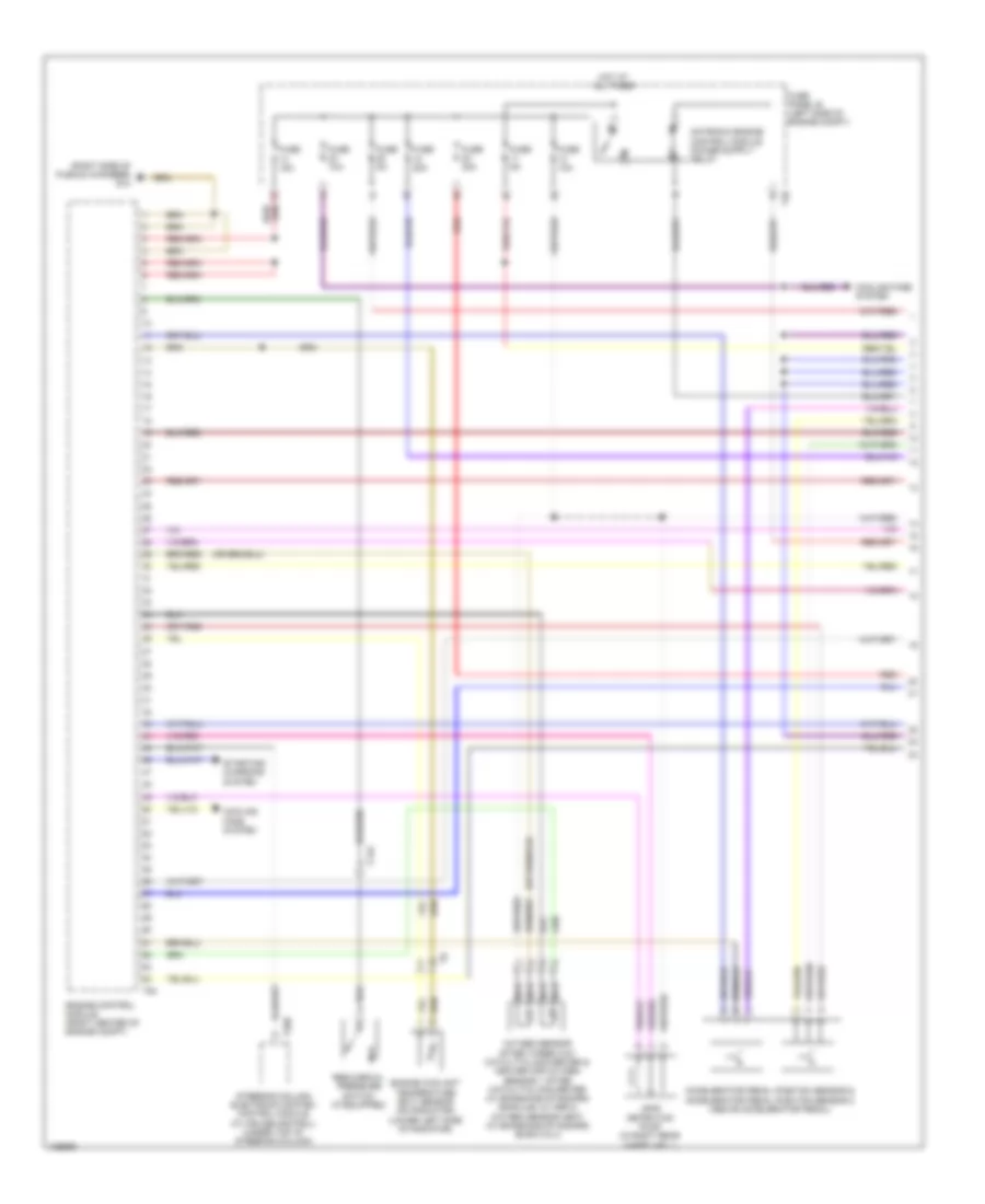
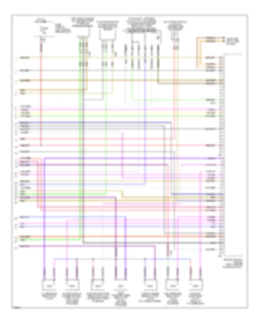
2.0L Turbo, Engine Performance Wiring Diagram (1 of 5) for Volkswagen Tiguan S 2014
 https://portal-diagnostov.com/license.html
Automotive Electricians Portal FZCO
Automotive Electricians Portal FZCO
https://portal-diagnostov.com/license.html
https://portal-diagnostov.com/license.html
Automotive Electricians Portal FZCO
Automotive Electricians Portal FZCO
List of elements for 2.0L Turbo, Engine Performance Wiring Diagram (1 of 5) for Volkswagen Tiguan S 2014:
- (right side of plenum chamber) g10
- Accelerator pedal position sensor & accelerator pedal position sensor 2 (above accelerator pedal)
- Cooling fans system
- Engine control module (right center of engine compt)
- Engine coolant temperature (ect) sensor (on radiator) (lower left side of radiator)
- Fuse 10a
- Fuse 15a
- Fuse 20a
- Fuse 30a
- Fuse 5a
- Fuse panel b (left side of engine compt)
- Hot at all times
- Leak detection pump (in right rear wheelwell)
- Nca
- Oxygen sensor after three way catalytic converter & heater for oxygen sensor 1 after catalytic converter (w/ emissions standard bin5/ulev & tier 2) oxygen sensor heat (w/ emissions standard euro 5 & 4)
- Red
- Reduced oil pressure switch (if equipped)
- Starting/ charging system
- Steering column electronic system control module (w/ cruise control) (under top of steering column)
- T14a
- T20d
- T40
- T94
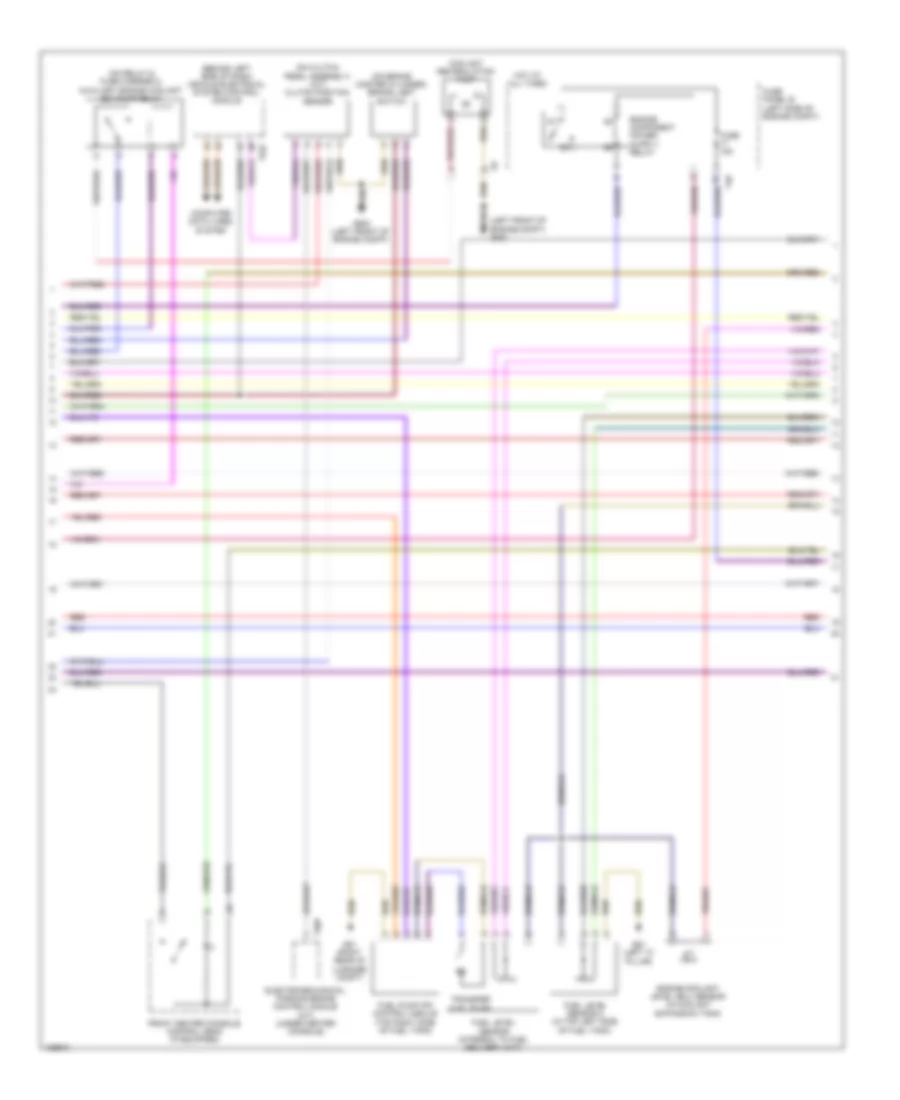
2.0L Turbo, Engine Performance Wiring Diagram (2 of 5) for Volkswagen Tiguan S 2014
 https://portal-diagnostov.com/license.html
Automotive Electricians Portal FZCO
Automotive Electricians Portal FZCO
https://portal-diagnostov.com/license.html
https://portal-diagnostov.com/license.html
Automotive Electricians Portal FZCO
Automotive Electricians Portal FZCOList of elements for 2.0L Turbo, Engine Performance Wiring Diagram (2 of 5) for Volkswagen Tiguan S 2014:
- (behind left side of dash) vehicle electrical system control module
- (left front of engine compt) g640
- (on brake master cylinder) brake light switch
- (on clutch pedal assembly) (m/t) clutch position sensor
- (on relay & fuse carrier 2) auxiliary engine coolant (ec) pump relay
- Computer data lines system
- Coolant recirculation pump
- Electromechanical parking brake control module (m/t) (under center console)
- Engine coolant level (ecl) sensor (in coolant expansion tank)
- Front center console control head (if equipped)
- Fuel level sensor (integral to fuel delivery unit)
- Fuel level sensor 2 (in top left side of fuel tank)
- Fuel pump (fp) control module (top right side of fuel tank)
- Fuse 15a
- Fuse panel b (left side of engine compt)
- G51 (right rear of luggage compt)
- G61 (left "c" pillar)
- G640 (left front of engine compt)
- Hot at all times
- Red
- T30p
- T40
- T52c
- Transfer fuel pump
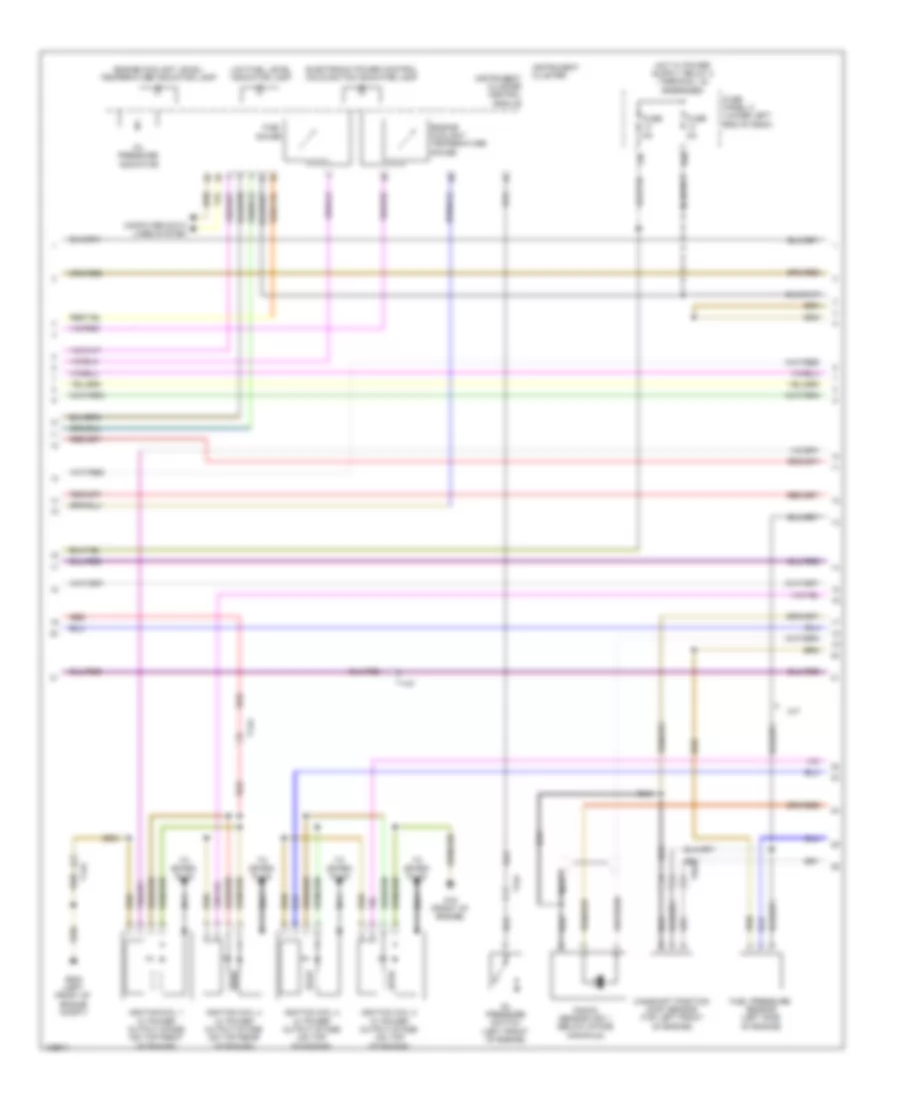
2.0L Turbo, Engine Performance Wiring Diagram (3 of 5) for Volkswagen Tiguan S 2014
 https://portal-diagnostov.com/license.html
Automotive Electricians Portal FZCO
Automotive Electricians Portal FZCO
https://portal-diagnostov.com/license.html
https://portal-diagnostov.com/license.html
Automotive Electricians Portal FZCO
Automotive Electricians Portal FZCOList of elements for 2.0L Turbo, Engine Performance Wiring Diagram (3 of 5) for Volkswagen Tiguan S 2014:
- 13b
- 14b
- Camshaft position (cmp) sensor (top left front of engine)
- Computer data lines system
- Electronic power control malfunction indicator lamp
- Engine coolant level/ temperature indicator lamp
- Engine coolant temperature gauge
- Fuel gauge
- Fuel pressure sensor (left side of engine)
- Fuse 5a
- Fuse panel c (lower left end of dash)
- G15 (front of engine)
- G640 (left front of engine compt)
- Ignition coil 1 w/ power output stage (on top front of engine)
- Ignition coil 2 w/ power output stage (on top of engine)
- Ignition coil 3 w/ power output stage (on top of engine)
- Ignition coil 4 w/ power output stage (on top rear of engine)
- Instrument cluster
- Instrument cluster control module
- Knock sensor (ks) 1 (below intake manifold)
- Low fuel level indicator lamp
- M/t
- Nca
- Oil pressure indicator
- Oil pressure switch (left front of engine)
- Red
- T14a
- T6af
- To spark plug
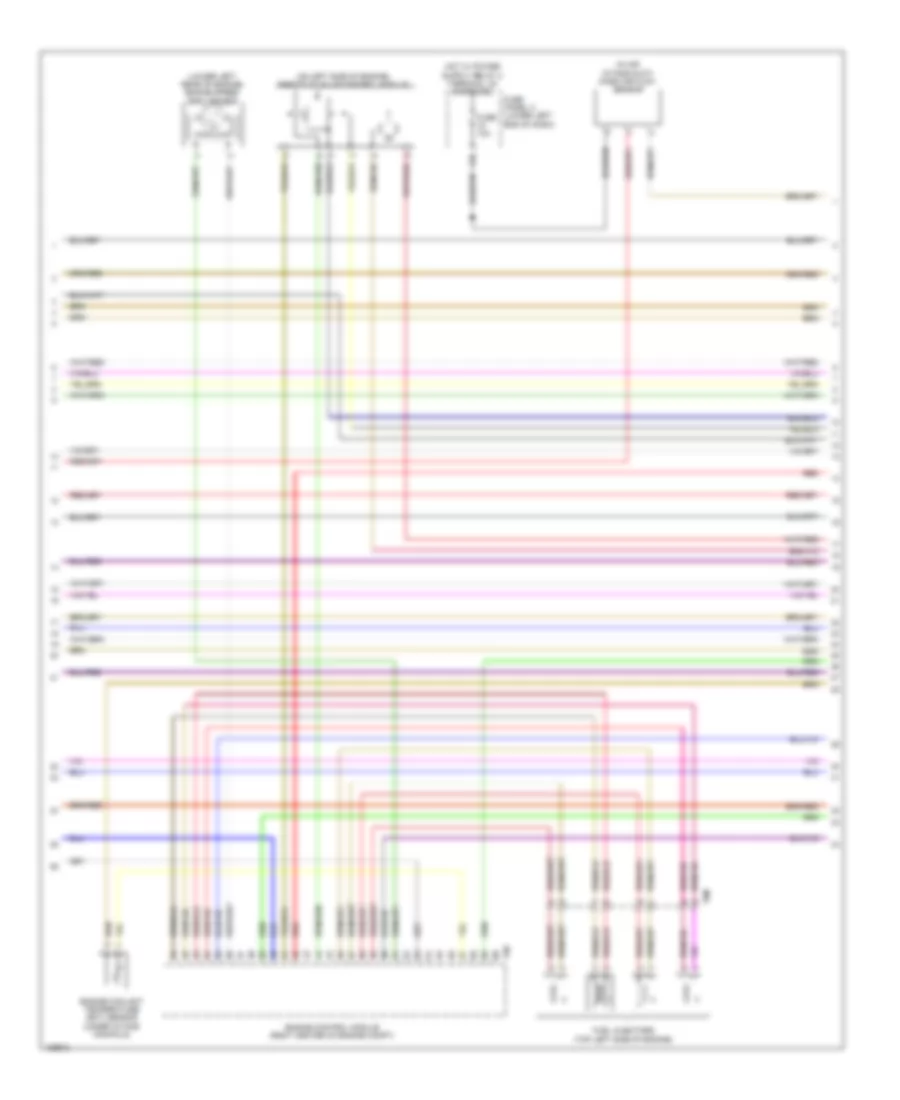
2.0L Turbo, Engine Performance Wiring Diagram (4 of 5) for Volkswagen Tiguan S 2014
 https://portal-diagnostov.com/license.html
Automotive Electricians Portal FZCO
Automotive Electricians Portal FZCO
https://portal-diagnostov.com/license.html
https://portal-diagnostov.com/license.html
Automotive Electricians Portal FZCO
Automotive Electricians Portal FZCOList of elements for 2.0L Turbo, Engine Performance Wiring Diagram (4 of 5) for Volkswagen Tiguan S 2014:
- (in air intake duct) mass air flow sensor
- (lower left rear of engine) engine speed (rpm) sensor
- (on left side of engine) throttle valve control module
- 15b
- Engine control module (right center of engine compt)
- Engine coolant temperature (ect) sensor (under intake manifold)
- Fuel injectors (top left side of engine)
- Fuse 10a
- Fuse panel c (lower left end of dash)
- Red
- T60
- T8m
2.0L Turbo, Engine Performance Wiring Diagram (5 of 5) for Volkswagen Tiguan S 2014
 https://portal-diagnostov.com/license.html
Automotive Electricians Portal FZCO
Automotive Electricians Portal FZCO
https://portal-diagnostov.com/license.html
https://portal-diagnostov.com/license.html
Automotive Electricians Portal FZCO
Automotive Electricians Portal FZCOList of elements for 2.0L Turbo, Engine Performance Wiring Diagram (5 of 5) for Volkswagen Tiguan S 2014:
- (in exhaust, upstream of catalytic converter) (w/ emissions standard bin5/ulev & tier 2) oxygen sensor heater & heated oxygen sensor
- (in intake manifold) intake manifold runner position sensor
- (left side of engine compt)
- (left side of engine, on upstream pipe) charge air pressure sensor
- (on intake manifold) intake air temperature (iat) sensor
- Camshaft adjustment valve 1 (front of cylinder bank)
- Computer data lines system
- Engine control module (right center of engine compt)
- Evap canister purge regulator valve 1 (left side of engine)
- Fuel pressure regulator valve (at rear of engine)
- Fuse 15a
- Fuse panel b
- Hot at all times
- Intake manifold runner control (imrc) valve (left rear of engine)
- Nca
- Oil pressure regulation valve
- Red
- T14a
- T40
- T60
- T6af
- T94
- Turbo charger recirculating valve (on turbocharger)
- Wastegate bypass regulator valve (lower right front of engine)

 Čeština
 Dansk
Dansk Deutsch
 Ελληνικά
 English
 English
 Español
 Suomi
Suomi Français
 Français
 עברית
עברית Hrvatski
 Magyar
 Italiano
 日本語
日本語 한국어
한국어 Nederlands
 Polski
 Português
 Português
 Română
 Русский
 Slovenčina
 Slovenščina
 Svenska
 Türkçe
