POWER DISTRIBUTION
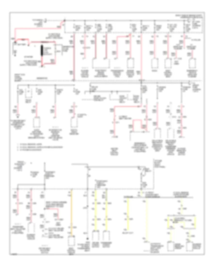
Power Distribution Wiring Diagram (1 of 4) for Chevrolet Impala Limited LTZ 2014
 https://portal-diagnostov.com/license.html
Automotive Electricians Portal FZCO
Automotive Electricians Portal FZCO
https://portal-diagnostov.com/license.html
https://portal-diagnostov.com/license.html
Automotive Electricians Portal FZCO
Automotive Electricians Portal FZCO
List of elements for Power Distribution Wiring Diagram (1 of 4) for Chevrolet Impala Limited LTZ 2014:
- (body wiring harness, 10 cm from second breakout to x302) j311
- (not used)
- (right kick panel) i/p fuse block
- (right side of engine compt) underhood fuse block
- 200a
- Abs mtr1 fuse 60a
- Abs mtr2 fuse 60a
- Air bag fuse 10a
- Amp fuse 25a
- Audio amplifier (w/ enhanced audio speaker system)
- Automatic transmission shift lock control solenoid
- Aux fuse 20a
- Batt 1 fuse 60a
- Batt 2 fuse 60a
- Batt 4 fuse 30a
- Battery
- Blower motor control module
- Body control module (bcm)
- Cnstr fuse 10a
- Digital radio receiver
- Door lock pcb relay
- Door unlock pcb relay
- Dr/lck fuse 25a
- Driver door unlock pcb relay
- Driver seat adjuster switch
- Driver window switch
- Ecm/ tcm fuse 15a
- Electronic brake control module (ebcm)
- Emergency vehicle headlamp flasher
- Emergency vehicle rear compartment lid lamp relay (if equipped)
- Engine control module (ecm)
- Evaporative emission (evap) canister vent solenoid valve
- From pwr/mir j fuse (diagram 1 of 4)
- G302 (floor, right of front passenger's seat)
- Generator
- Generator inline fuse
- Hdlp mdl fuse 15a
- Heated seat control module
- Htd/ seat fuse 20a
- I/p fuse block (right kick panel)
- Inflatable restraint front passenger presence system (pps) module
- Inflatable restraint sensing & diagnostic module (sdm)
- Inside rearview mirror
- Int lts/ pnl dim fuse 15a
- J375
- Outside rearview mirror switch
- Passenger seat adjuster switch (if equipped)
- Passenger window switch
- Pwr/mir fuse 2a
- Pwr/seat circuit breaker 25a
- Pwr/wndw circuit breaker 25a
- Radio
- Radio fuse 20a
- Rap fuse 10a
- Rap relay
- Red
- S/roof fuse 20a
- Starter
- Sunroof control module
- Tan
- To center seat accessory power outlet (diagram 2 0f 4)
- To fusible link (diagram 2 of 4)
- To rt t/sig fuse (diagram 2 of 4)
- To s/roof fuse (diagram 1 of 4)
- Transmission control module (tcm)
- Trunk relay
- W/ 8 way driver seat adjuster
- W/ digital audio
- W/ dual reading lamps
- W/ dual reading lamps & power sliding roof
- W/ dual reading lamps or power sliding roof
- W/ front compartment floor console
- W/ front seat heater
- W/ headlamp flasher
- W/ police
- W/ power sliding roof
- W/o 8 way driver seat adjuster
- W/o headlamp flasher
- X1 b1
- X1 c2
- X122
- X200 a2
- X200 a8
- X210
- X3 b1
- X311 a
- X311 g
- X313
- X313 a
- X398
- X398 f
- X4 d2
- X4 f1
- X409 b
- X490 a6
- X490 b6
- X500 a2
- X500 c2
- X503 a2
- X503 c2
- X600
- X600 a2
- X604 a
- Xm fuse 10a
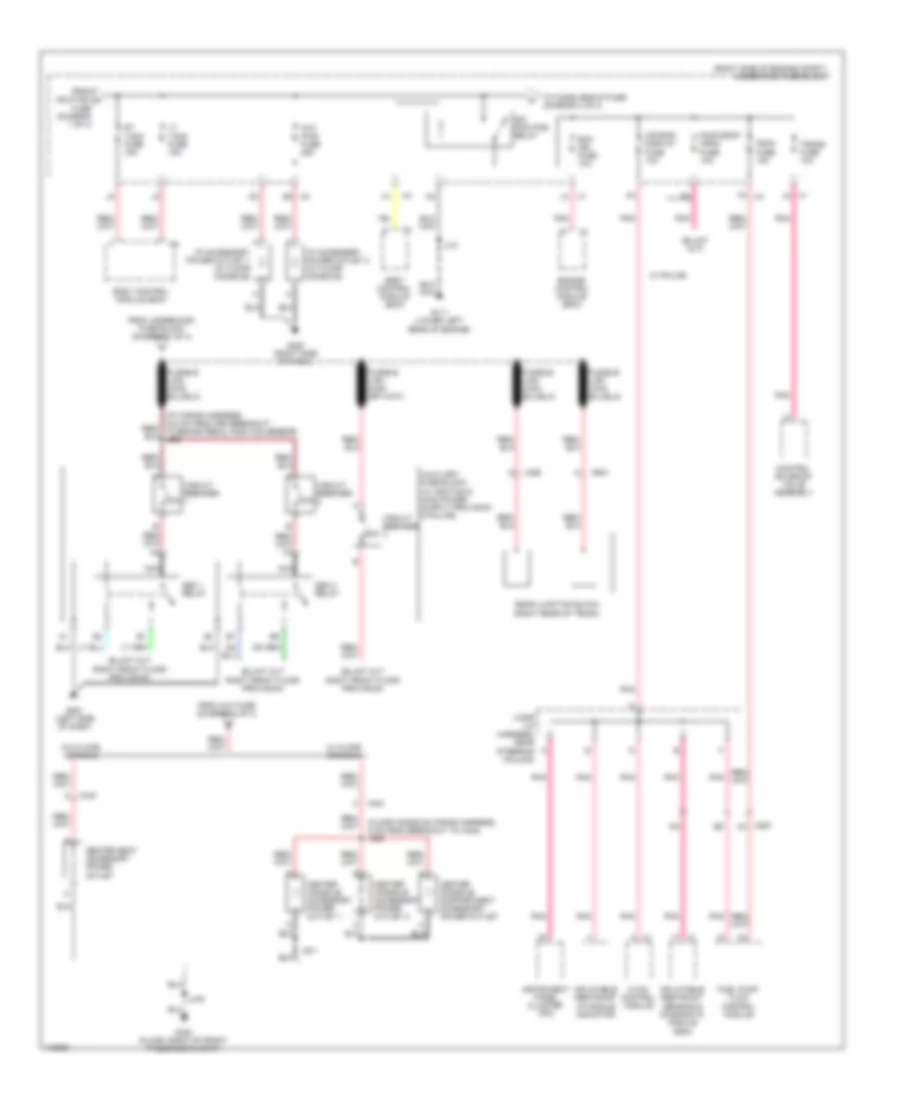
Power Distribution Wiring Diagram (2 of 4) for Chevrolet Impala Limited LTZ 2014
 https://portal-diagnostov.com/license.html
Automotive Electricians Portal FZCO
Automotive Electricians Portal FZCO
https://portal-diagnostov.com/license.html
https://portal-diagnostov.com/license.html
Automotive Electricians Portal FZCO
Automotive Electricians Portal FZCOList of elements for Power Distribution Wiring Diagram (2 of 4) for Chevrolet Impala Limited LTZ 2014:
- (floor console wiring harness, 5 cm from breakout to x340) j238
- (right side of engine compt) underhood fuse block
- 30a
- 50a
- Air bag/ display fuse 10a
- Aux pwr fuse 25a
- Body control module (bcm)
- Center console accessory power outlet 1
- Center console accessory power outlet 2
- Center console compartment accessory power outlet
- Center seat accessory power outlet
- Circuit breaker
- Control solenoid valve assembly
- Ecm ign fuse 10a
- Engine control module (ecm)
- F3 x4
- From aux fuse (diagram 1 of 4)
- From hdlp mdl a fuse (diagram 1 of 4)
- From underhood fuse block (diagram 1 of 4)
- Fscm fuse 15a
- Fuel pump flow control module
- G111 (lower left rear of engine)
- G200 (right side of dash)
- G201 (left side of dash)
- G302 (floor, right of front passenger's seat)
- Hvac control module
- I/p accessory power outlet 1 (w/ floor console)
- I/p accessory power outlet 2 (w/ floor console)
- Ign main pcb relay
- Inflatable restraint i/p module indicator
- Inflatable restraint sensing & diagnostic module (sdm)
- Instrument panel cluster (ipc)
- J101
- J2 x1
- J231
- J3 x1
- J375
- Jx206 (i/p harness, near steering column)
- Lt t/sig fuse 15a
- Nca
- Pnk
- Pwr drop/ crnk fuse 10a
- Rear junction block (right rear of trunk)
- Rt t/sig fuse 15a
- Seo 1 relay
- Seo 2 relay
- To chmsl/bckup fuse (diagram 3 of 4)
- Trans fuse 10a
- W/ floor console
- W/ police
- W/o floor console
- X2 e2
- X200 a3
- X340
- X360
- X362
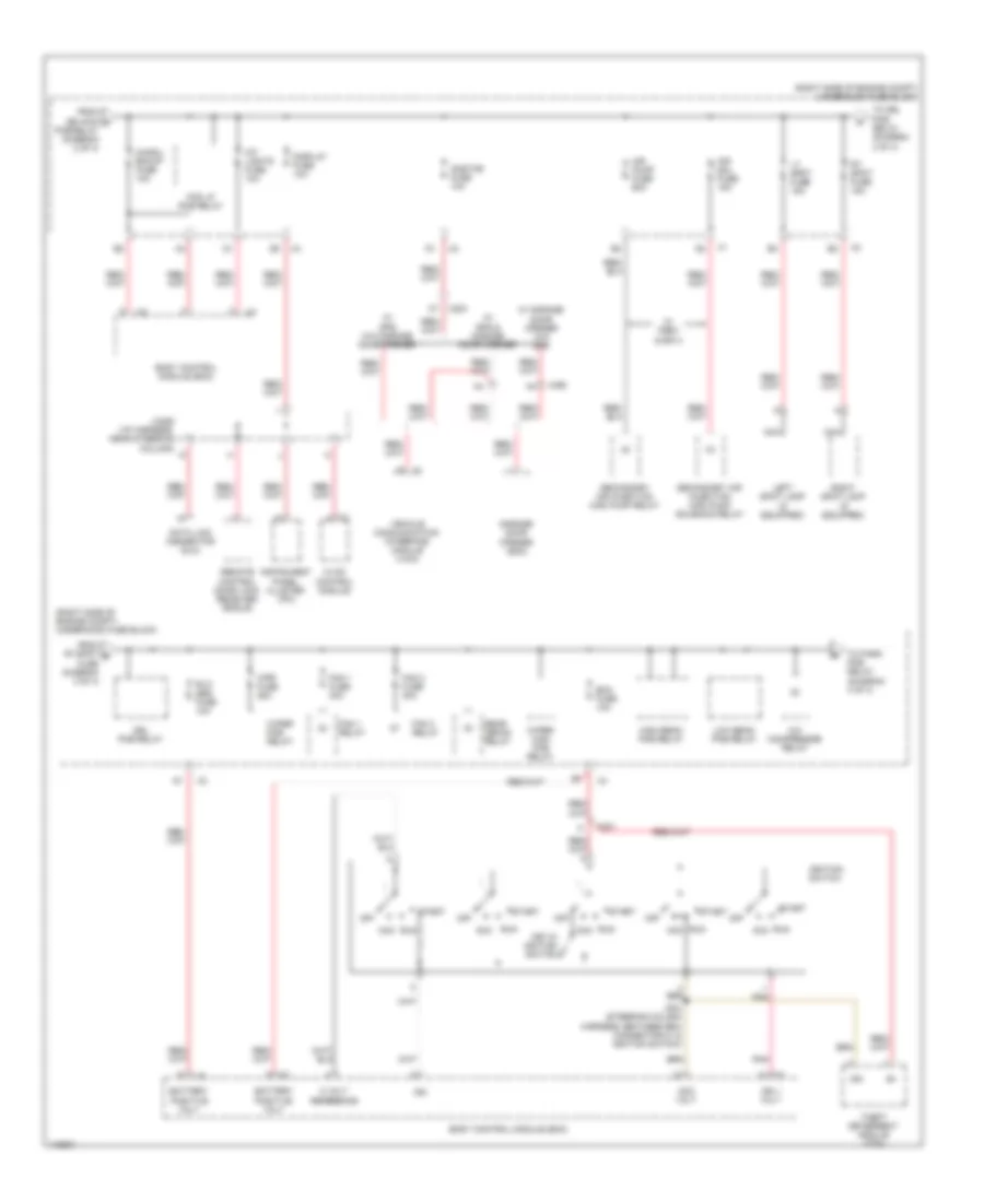
Power Distribution Wiring Diagram (3 of 4) for Chevrolet Impala Limited LTZ 2014
 https://portal-diagnostov.com/license.html
Automotive Electricians Portal FZCO
Automotive Electricians Portal FZCO
https://portal-diagnostov.com/license.html
https://portal-diagnostov.com/license.html
Automotive Electricians Portal FZCO
Automotive Electricians Portal FZCOList of elements for Power Distribution Wiring Diagram (3 of 4) for Chevrolet Impala Limited LTZ 2014:
- (right side of engine compt) underhood fuse block
- 5 volt reference
- A/c compressor relay
- Acc
- Acc volt
- Air pump fuse 60a
- Air sol fuse 15a
- Battery positive volt
- Bcm fuse 10a
- Body control module (bcm)
- Chmsl/ bckup fuse 10a
- Data link connector (dlc)
- Display fuse 10a
- Drl pcb relay
- Fan 1 fuse 30a
- Fan 1 relay
- Fan 2 fuse 30a
- Fan 3 relay
- Fog lp pcb relay
- From ign main c pcb relay (diagram 2 of 4)
- From rt spot d fuse (diagram 3 of 4)
- Garage door opener (gdo)
- High beam pcb relay
- Hvac control module
- Ign
- Ign 1 volt
- Ignition switch
- Instrument panel cluster (ipc)
- Int lights fuse 10a
- J204 (steering column harness, between bcm connector x1 & ignition switch)
- Jx206 (i/p harness, near steering column)
- Key in ignition switch
- Left spot lamp (if equipped)
- Low beam pcb relay
- Lt spot fuse 15a
- Nca
- Off
- Onstar fuse 10a
- Pnk
- Rear defog relay
- Remote control door lock receiver (rcdlr)
- Right spot lamp (if equipped)
- Rt spot fuse 15a
- Run
- Rvc sen fuse 10a
- Secondary air injection (air) pump relay
- Secondary air injection (air) pump solenoid relay
- Start
- Theft deterrent module (tdm)
- To drl pcb relay (diagram 3 of 4)
- To park pcb relay (diagram 4 of 4)
- Vehicle communication interface module (vcim)
- W/ garage door opener w/o gps
- W/ gps & garage door opener
- W/ gps w/o garage door opener
- W/ pzev & bin 4
- Wiper high pcb relay
- Wiper pcb relay
- Wpr fuse 25a
- X201
- X203 c7
- X490
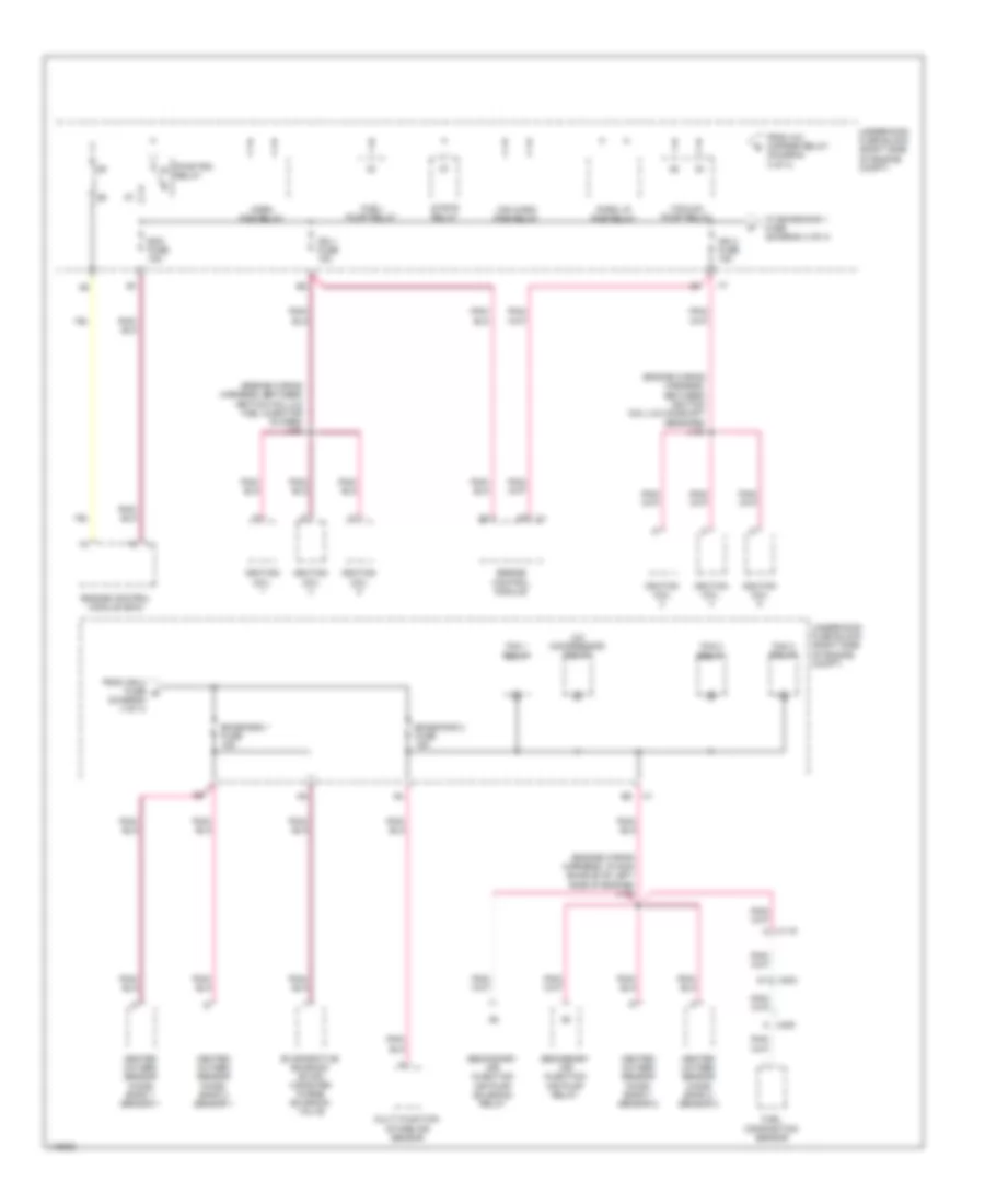
Power Distribution Wiring Diagram (4 of 4) for Chevrolet Impala Limited LTZ 2014
 https://portal-diagnostov.com/license.html
Automotive Electricians Portal FZCO
Automotive Electricians Portal FZCO
https://portal-diagnostov.com/license.html
https://portal-diagnostov.com/license.html
Automotive Electricians Portal FZCO
Automotive Electricians Portal FZCOList of elements for Power Distribution Wiring Diagram (4 of 4) for Chevrolet Impala Limited LTZ 2014:
- (engine wiring harness, between ignition coil 2 & camshaft sensors) j164
- (engine wiring harness, between ignition coil 5 & fuel injector inlines) j162
- (engine wiring harness, in main bundle on left side of engine) j109
- A/c compressor relay
- Ecm fuse 15a
- Emissions 1 fuse 15a
- Emissions 2 fuse 15a
- Engine control module
- Engine control module (ecm)
- Evaporative emission (evap) canister purge solenoid valve
- Fan 1 relay
- Fan 2 relay
- Fan 3 relay
- From a/c cmprsr relay (diagram 3 of 4)
- From ign 2 fuse g (diagram 4 of 4)
- Fuel composition sensor
- Fuel/ pump relay
- Heated oxygen sensor (ho2s) bank 1 sensor 1
- Heated oxygen sensor (ho2s) bank 1 sensor 2
- Heated oxygen sensor (ho2s) bank 2 sensor 1
- Heated oxygen sensor (ho2s) bank 2 sensor 2
- Horn pcb relay
- Ign 1 fuse 15a
- Ign 2 fuse 15a
- Ignition coil
- Multi function intake air sensor
- Park lp pcb relay
- Pwr/trn relay
- Secondary air injection air pump relay
- Secondary air injection air pump solenoid relay
- Strtr relay
- To emissions 1 fuse (diagram 4 of 4)
- Underhood fuse block (right side of engine compt)
- Vacuum pump relay
- Ws wash pcb relay
- X115
- X203
- X405 a

 Čeština
 Dansk
Dansk Deutsch
 Ελληνικά
 English
 English
 Español
 Suomi
Suomi Français
 Français
 עברית
עברית Hrvatski
 Magyar
 Italiano
 日本語
日本語 한국어
한국어 Nederlands
 Polski
 Português
 Português
 Română
 Русский
 Slovenčina
 Slovenščina
 Svenska
 Türkçe
