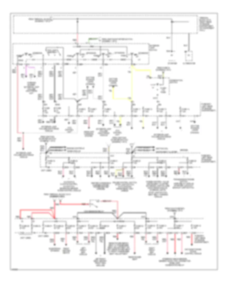
POWER DISTRIBUTION
Power Distribution Wiring Diagram (1 of 2) for Mercedes-Benz S500 1997
 https://portal-diagnostov.com/license.html
Automotive Electricians Portal FZCO
Automotive Electricians Portal FZCO
https://portal-diagnostov.com/license.html
https://portal-diagnostov.com/license.html
Automotive Electricians Portal FZCO
Automotive Electricians Portal FZCO
List of elements for Power Distribution Wiring Diagram (1 of 2) for Mercedes-Benz S500 1997:
- (battery harness)
- (canada)
- (left
- (left rear
- (left rear of engine
- (not used)
- (right front
- (right rear
- (w/ asr)
- (w/o asr)
- 15a
- 15c
- 15r
- 15x
- 15z
- 17/1
- 17/2
- 20/1
- 20/2
- 30z
- 32/1
- 32/2
- 71/2
- 74/1
- 74/2
- A/c system blower unit
- Abs/asr hydraulic unit
- Accy
- Air control module
- Airbag indicator
- Anti- theft alarm system, infrared remote control, rear heated seats
- Anti-theft alarm system, infrared remote control, rear head restraints
- Asr/sps control module
- Base module
- Battery
- Central locking, closing assist
- Closing assist
- Combination relay
- Combination relay, ignition coils
- Compart-
- Compartment)
- Compartment, on component
- Daytime running lamps
- Electrolytic capacitor
- Engine controls system
- Ets/sps control module
- Footwell)
- Front cigar lighter
- Fuel pumps
- Fuse
- Fuse 10a
- Fuse 15a
- Fuse 20a
- Fuse 25a
- Fuse 30a
- Fuse 40a
- Fuse 7.5a
- Fuse box
- G203 (right
- G302 (below center console)
- G303 (below right rear seat)
- G405 (right side
- Head- lights system
- Heated rear window
- Heated seats
- Heated seats, seat belt extender, srs control unit
- High pressure return pump relay
- Ignition/ starter switch
- Infrared central locking
- Maxi- fuse box
- Ment)
- Nca
- Of engine
- Of engine compart-
- Of luggage
- Off
- Power windows
- Power windows, trunk lamp, rear interior lamp, rear reading lamp, rear entrance/ exit lamp, central locking, anti-theft system, taillamps
- Radio sound system: tuner & amplifier
- Rear cigar lighter
- Rear climate control
- Rear fuse box
- Rear of engine
- Rear window sunshield, convenience control module
- Red
- Red red
- Run
- Seat belt extenders
- Seatbelt warning module, instrument cluster
- Sliding/ pop-up roof
- Srs control unit
- Start
- Starter lock-out/ relay module, cruise control module, engine control module, daytime running light control unit
- Tele- phone
- Terminal block x/4
- Terminal block x4/10
- Terminal block x4/20
- Terminal block x4/5
- To combination switch (diagram 2 of 2)
- To exterior lamp switch (diagram 2 of 2)
- To fuse box (diagram 2 of 2)
- To terminal block (diagram 2 of 2)
- Ultrasonic pts control module
- Wall)
- Wiper motor
- Wiper relay, washer pump, combination relay, rear window defogger switch
Power Distribution Wiring Diagram (2 of 2) for Mercedes-Benz S500 1997
 https://portal-diagnostov.com/license.html
Automotive Electricians Portal FZCO
Automotive Electricians Portal FZCO
https://portal-diagnostov.com/license.html
https://portal-diagnostov.com/license.html
Automotive Electricians Portal FZCO
Automotive Electricians Portal FZCOList of elements for Power Distribution Wiring Diagram (2 of 2) for Mercedes-Benz S500 1997:
- (bridge)
- (canada)
- (not used)
- (right rear
- 12/1
- 12/2
- 14/1
- 14/2
- 14/3
- 15r/30
- 22/1
- 22/2
- 22/3
- 24/3
- 28/1
- 28/2
- 28/3
- 29/2
- 3/1
- 31/2
- 36/1
- 36/2
- 37/1
- 37/2
- 5/1
- 5/2
- 56a
- 56b
- 58l
- 58n
- 58ns
- 58r
- 63/2
- 65/1
- 68/2
- 69/1
- 69/2
- 78/1
- 78/2
- 82/1
- 82/2
- 9/1
- Air conditioning, ir das control module
- Alternator
- Ata control unit
- Automatic climate control, a/c switch, emissions sensor, ir das control module
- Base module
- Combination switch
- Compartment)
- Compartment, on component
- Convenience relay
- Cruise control switch, stop lamp switch, auto dimming inside rear view mirror
- Daytime running lamps
- Electronic antenna
- Engine controls
- Exterior lamp failure monitoring module
- Exterior lamp switch
- Flash -to- pass
- Fog lamp switch
- From fuse 15 (diagram 1 of 2)
- From ignition/ starter switch (diagram 1 of 2)
- From ignition/starter switch (diagram 1 of 2)
- From maxi-fuse box (diagram 1 of 2)
- From terminal block a (diagram 1 of 2)
- From terminal block x4/10 (diagram 1 of 2)
- Front heated seats
- Fuse 10a
- Fuse 11 7.5a
- Fuse 12 7.5a
- Fuse 13 7.5a
- Fuse 14 7.5a
- Fuse 17 20a
- Fuse 18 15a
- Fuse 19 7.5a
- Fuse 20 10a
- Fuse 21 15a
- Fuse 23 7.5a
- Fuse 24 7.5a
- Fuse 25 15a
- Fuse 27
- Fuse 28 7.5a
- Fuse 29 20a
- Fuse 30 20a
- Fuse 31 30a
- Fuse 32 30a
- Fuse 33
- Fuse 36 10a
- Fuse 37 30a
- Fuse 38 30a
- Fuse 40 30a
- Fuse 41 30a
- Fuse 7 10a
- Fuse 7.5a
- Fuse 8 7.5a
- Fuse 9 7.5a
- Fuse box (left rear of engine
- Head
- Headlamp cleaning system
- Heated windshield washer system, power/heated mirrors,
- Ignition coil
- Instrument cluster
- K30
- Left front esa module
- Left/right seat memory, front esa modules
- Nca
- Nse
- Of engine
- Off
- P30
- Park
- Purge control valve, instrument cluster, exterior lamp failure monitoring module, interior lights,
- Rear power bench seat w/ passenger seat adjustment or left rear power seat w/ front passenger seat adjustment
- Rear power seat
- Red
- Right front esa module
- Standing
- Starter
- Steering angle sensor, generic scan tool connector, dome lamp, combination relay
- Stop lamp switch, seat belt warning module
- Terminal block x4/10
- Transmission range switch horn relay module starter lock-out/ backup lamp switch,
- Wall)
- Warning buzzer, exterior lamp failure monitoring unit

 Čeština
 Dansk
Dansk Deutsch
 Ελληνικά
 English
 English
 Español
 Suomi
Suomi Français
 Français
 עברית
עברית Hrvatski
 Magyar
 Italiano
 日本語
日本語 한국어
한국어 Nederlands
 Polski
 Português
 Português
 Română
 Русский
 Slovenčina
 Slovenščina
 Svenska
 Türkçe
