ENGINE PERFORMANCE
2.4L
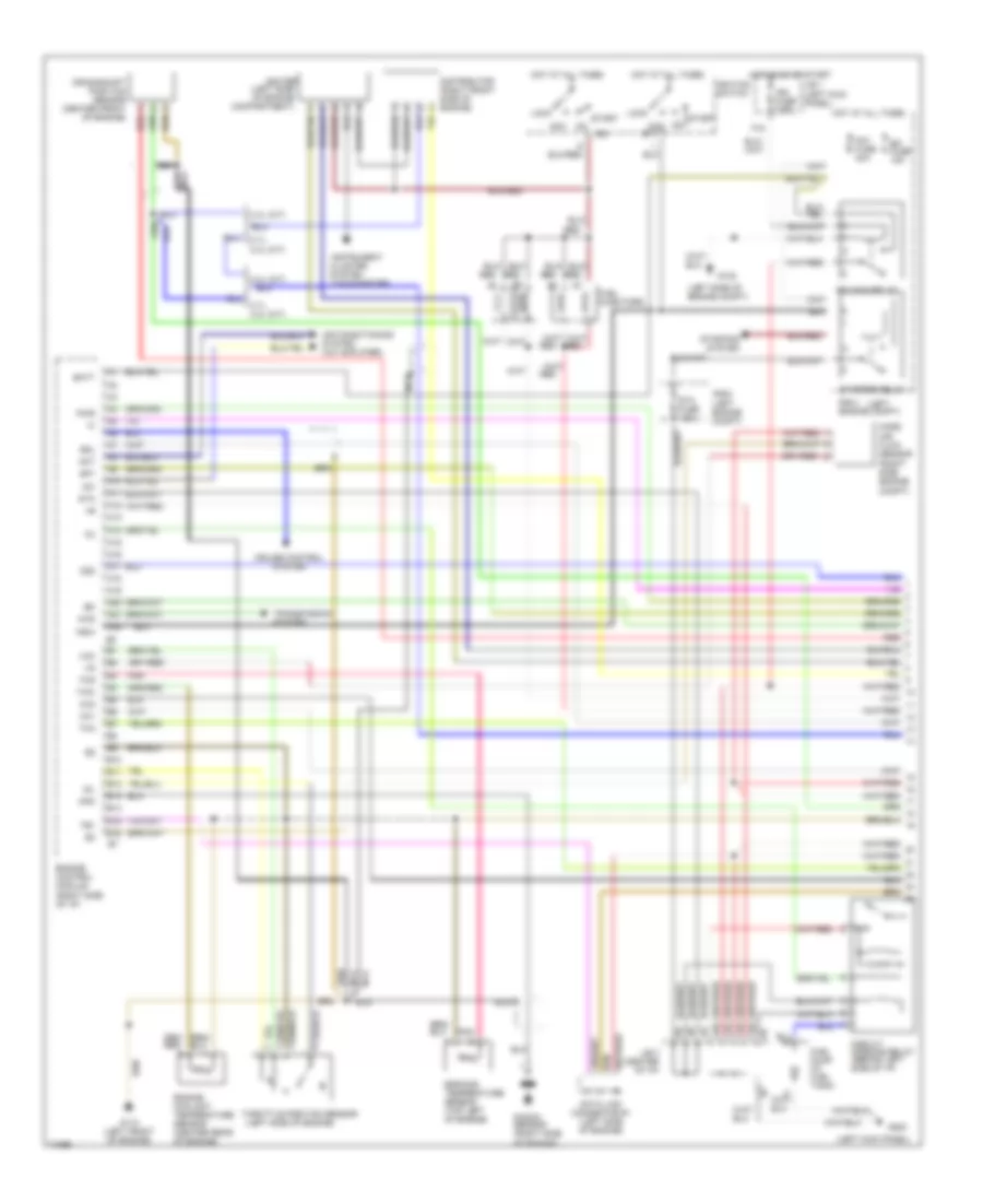
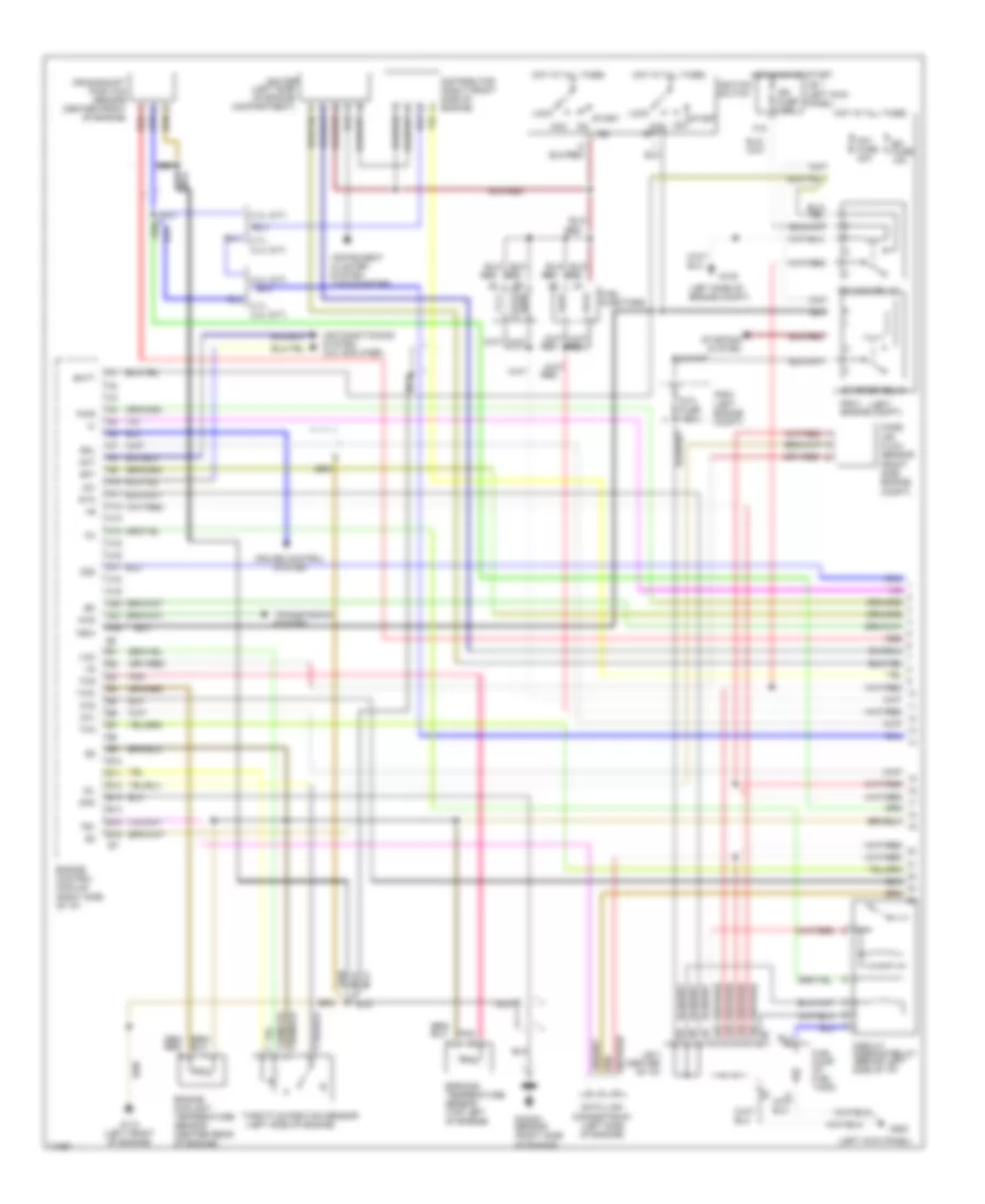
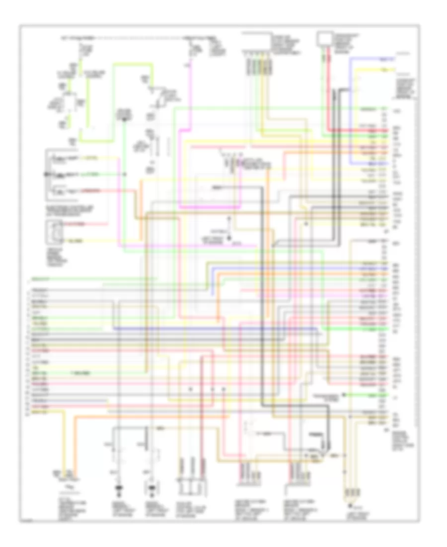
2.4L, Engine Performance Wiring Diagrams (1 of 2) for Toyota Tacoma 1995
 https://portal-diagnostov.com/license.html
Automotive Electricians Portal FZCO
Automotive Electricians Portal FZCO
https://portal-diagnostov.com/license.html
https://portal-diagnostov.com/license.html
Automotive Electricians Portal FZCO
Automotive Electricians Portal FZCO
List of elements for 2.4L, Engine Performance Wiring Diagrams (1 of 2) for Toyota Tacoma 1995:
- (left
- (left engine compt)
- (left kick panel)
- (left side of engine compartment)
- (left side of engine compt)
- (left side of engine)
- (tachometer)
- 12e
- 13e
- 14e
- 15e
- 2.4l (a/t)
- 2.7l, 2.4l (m/t)
- 4wd
- A10
- A11
- A12
- A13
- A14
- A15
- A16
- A17
- A18
- A19
- A20
- A21
- A22
- Acc
- Acc st1
- Aci
- Act
- Air conditioning system (a/c amplifier)
- Am1 fuse 40a
- B10
- B11
- B12
- B13
- B14
- B15
- B16
- Batt
- Circuit opening relay (behind left side of i/p)
- Cluster system
- Crankshaft position sensor (center front of engine)
- Cruise control system
- Data link connector #1 (left side of engine)
- Distributor (right front side of engine)
- Efi fuse 15a
- Efi main relay
- Egr gas temperature sensor (top left of engine)
- Engine control module (right side of i/p)
- Engine coolant temperature sensor (center rear of engine)
- F15
- Fuel injectors
- Fuel pump (in fuel tank)
- G102
- G110 (left front of engine)
- G200
- Hot at all times
- Hot in on or start
- Idl
- Ig2
- Ign fuse 7.5a
- Igniter
- Ignition switch
- Instrument
- J/b 1 (left kick panel)
- J/b 3 (center of i/p)
- Knk
- Knock sensor (right side of engine)
- Lock
- Mass air flow sensor (right side engine compt)
- Nca
- Nca nca
- Nsw
- Od2
- Ox1
- Ox2
- Pnk
- Pwr
- R/b 2
- R/b 2 engine compt)
- Red
- Sdl
- Sp1
- Sta
- Sta fuse 7.5a
- Start
- Starter relay
- Starting
- System
- Te1
- Tha
- Thg
- Throttle position sensor
- Thw
- Transmission system
- Vcc
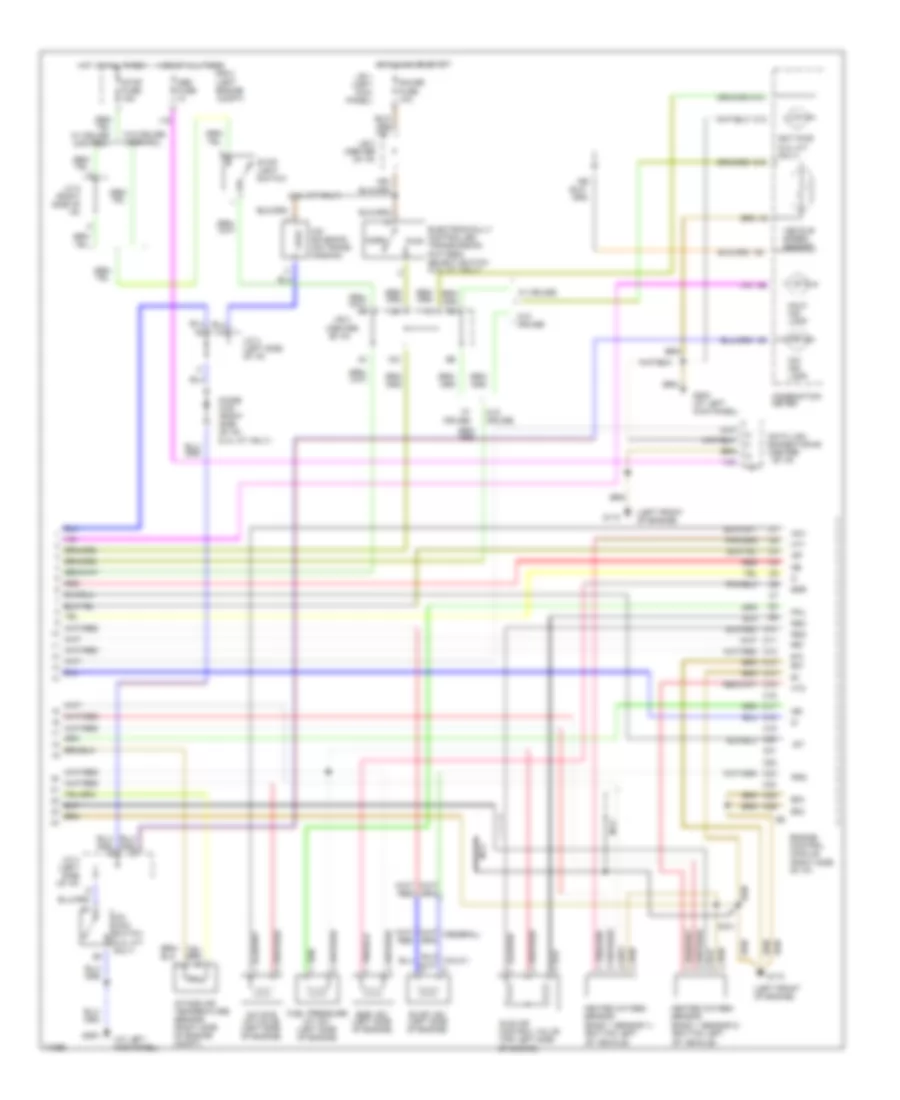
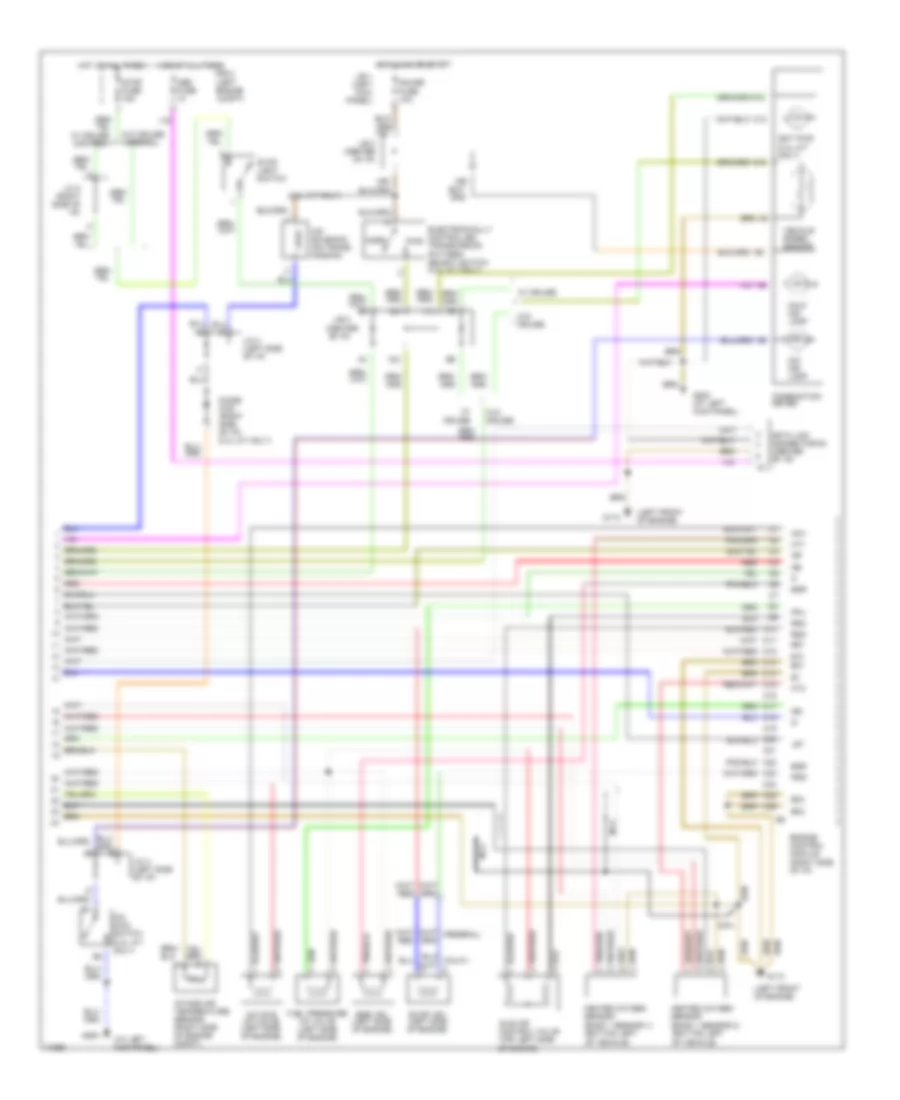
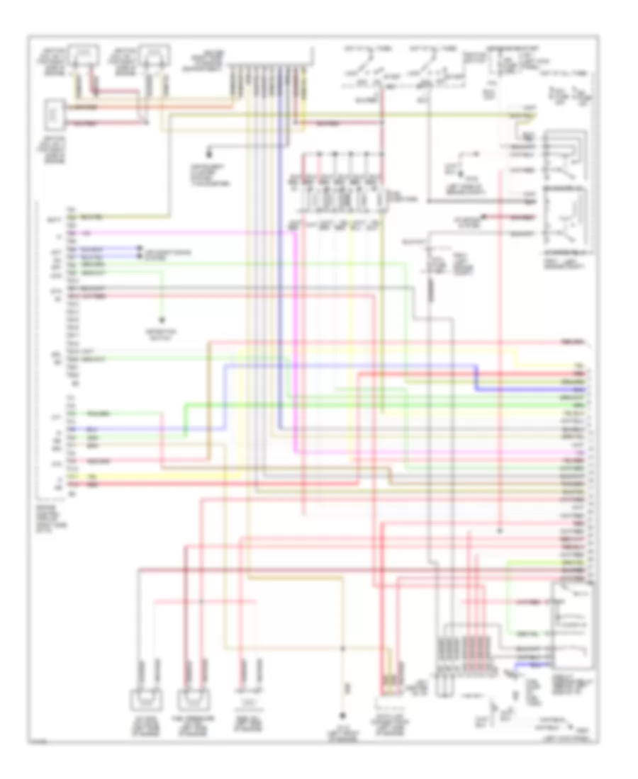
2.4L, Engine Performance Wiring Diagrams (2 of 2) for Toyota Tacoma 1995
 https://portal-diagnostov.com/license.html
Automotive Electricians Portal FZCO
Automotive Electricians Portal FZCO
https://portal-diagnostov.com/license.html
https://portal-diagnostov.com/license.html
Automotive Electricians Portal FZCO
Automotive Electricians Portal FZCOList of elements for 2.4L, Engine Performance Wiring Diagrams (2 of 2) for Toyota Tacoma 1995:
- #10
- #20
- (2.4l a/t only)
- (at left kick panel)
- (center of i/p)
- (left front of engine)
- 11c
- 12c
- 13c
- 16d
- 19d
- A/c idle up valve (left side of engine)
- Acv
- C16
- C19
- C21
- C22
- C24
- Combination meter
- Connector #3
- Data link
- Diode (o/d) (right side of i/p) (2.4l a/t only)
- E01
- E02
- E03
- Ect pwr (2.4l a/t only)
- Egr
- Egr vsv (left side of engine)
- Electronically controlled transmission pattern select switch (2.4l a/t only)
- Engine control module (right side of i/p)
- Evap vsv (left side of engine)
- Fpu
- Fuel pressure up vsv (left side of engine)
- G110
- G200
- G200 (at left kick panel)
- Gauge fuse 10a
- Heated oxygen sensor (bank 1 sensor 1) (bottom left of vehicle)
- Heated oxygen sensor (bank 1 sensor 2) (bottom left of vehicle)
- Hot at all times
- Hot in on or start
- Ht1
- Ht2
- Idle air control valve (top left side of engine)
- Igf
- Igt
- Intake air temperature sensor (right side of engine compt)
- J/b 1 (left kick panel)
- J/b 3
- J/b 3 (center of i/p)
- J/c 4 (left side of i/p)
- J/c 8 (right side of i/p)
- Malf. ind. lamp
- Nca
- Ne-
- Norm
- O/d ind. lamp
- O/d main switch (2.4l a/t only)
- O/d solenoid (on trans- mission)
- Obd fuse
- Prg
- Pwr
- R/b 2 (left engine compt)
- Red
- Rsc
- Rso
- Stop fuse 15a
- Stop light switch
- Vehicle speed sensor
- W/ cruise
- W/ cruise control
- W/o cruise
- W/o cruise control
2.7L
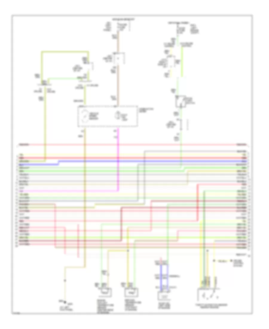
2.7L, Engine Performance Wiring Diagrams, A/T (1 of 2) for Toyota Tacoma 1995
 https://portal-diagnostov.com/license.html
Automotive Electricians Portal FZCO
Automotive Electricians Portal FZCO
https://portal-diagnostov.com/license.html
https://portal-diagnostov.com/license.html
Automotive Electricians Portal FZCO
Automotive Electricians Portal FZCOList of elements for 2.7L, Engine Performance Wiring Diagrams, A/T (1 of 2) for Toyota Tacoma 1995:
- (left
- (left engine compt)
- (left kick panel)
- (left side of engine compartment)
- (left side of engine compt)
- (left side of engine)
- (tachometer)
- 12e
- 13e
- 14e
- 15e
- 4wd
- A/t oil temperature sensor (center rear of engine compt)
- Acc
- Acc st1
- Aci
- Act
- Air conditioning system (a/c amplifier)
- Am1 fuse 40a
- Batt
- Circuit opening relay (behind left side of i/p)
- Cluster system
- Crankshaft position sensor (center front of engine)
- Cruise control system
- D10
- D11
- D12
- D13
- D14
- D15
- D16
- D17
- D18
- D19
- D20
- D21
- D22
- Data link connector #1 (left side of engine)
- Distributor (right front side of engine)
- E10
- E11
- E12
- Efi fuse 15a
- Efi main relay
- Egr gas temperature sensor (top left of engine)
- Engine control module (right side of i/p)
- Engine coolant temperature sensor (center rear of engine)
- F10
- F11
- F12
- F13
- F14
- F15
- F16
- Fuel injectors
- Fuel pump (in fuel tank)
- G102
- G110 (left front of engine)
- G200
- Hot at all times
- Hot in on or start
- Idl
- Ig2
- Ign fuse 7.5a
- Igniter
- Ignition switch
- Instrument
- J/b 1 (left kick panel)
- J/b 3 (center of i/p)
- Knk
- Knock sensor (right side of engine)
- Lock
- Mass air flow sensor (right side engine compt)
- Nca
- Nca nca
- Ne-
- Nsw
- Od1
- Od2
- Oil -w
- Ox1
- Ox2
- Pnk
- Prg
- Pwr
- R/b 2
- R/b 2 engine compt)
- Red
- Sdl
- Sp1
- Sp2+
- Sp2-
- Sta
- Sta fuse 7.5a
- Start
- Starter relay
- Starting
- System
- Te1
- Tfn
- Tha
- Thg
- Throttle position sensor
- Thw
- Transmission system
- Vcc
- Vehicle speed sensor (on trans- mission)
- Vta
2.7L, Engine Performance Wiring Diagrams, A/T (2 of 2) for Toyota Tacoma 1995
 https://portal-diagnostov.com/license.html
Automotive Electricians Portal FZCO
Automotive Electricians Portal FZCO
https://portal-diagnostov.com/license.html
https://portal-diagnostov.com/license.html
Automotive Electricians Portal FZCO
Automotive Electricians Portal FZCOList of elements for 2.7L, Engine Performance Wiring Diagrams, A/T (2 of 2) for Toyota Tacoma 1995:
- #10
- #20
- (at left kick panel)
- (center of i/p)
- (column a/t)
- (left front of engine)
- * column a/t only
- 11c
- 12c
- 13b
- 13c
- 14b
- 16d
- 19d
- 2 ind.
- A/c idle up valve (left side of engine)
- A/t indicator switch (on trans- mission)
- A/t oil temp ind.
- A10
- Acv
- C13
- Canada
- Cig fuse 15a
- Combination meter
- Connector #3
- Cruise control system
- D ind.
- D n
- Data link
- Diode (center of i/p) (canada)
- E01
- E02
- E03
- Ect pwr
- Egr
- Egr vsv (left side of engine)
- Electronic controlled transmission solenoid (on transmission)
- Electronically controlled transmission pattern select switch
- Engine control module (right side of i/p)
- Evap vsv (left side of engine)
- Fpu
- Fuel pressure up vsv (left side of engine)
- G110
- G15
- G18
- G19
- G200
- G27
- G28
- Gauge fuse 10a
- Heated oxygen sensor (bank 1 sensor 1) (bottom left of vehicle)
- Heated oxygen sensor (bank 1 sensor 2) (bottom left of vehicle)
- Hot at all times
- Hot in acc or on
- Hot in on or start
- Ht1
- Ht2
- Idle air control valve (top left side of engine)
- Igf
- Igt
- Intake air temperature sensor (right side of engine compt)
- J/b 1 (left kick panel)
- J/b 3
- J/b 3 (center of i/p)
- J/c 4 (left side of i/p)
- J/c 8 (right side of i/p)
- L ind.
- Malf. ind. lamp
- N ind.
- Nca
- Norm
- O/d ind. lamp
- O/d main switch
- Obd fuse
- Oil
- Only
- P ind.
- Pnk
- Pwr
- R ind.
- R/b 2 (left engine compt)
- Rsc
- Rso
- Stop fuse 15a
- Stop light switch
- Transmission system
- Us only
- Vehicle speed sensor
- W/ column a/t
- W/ cruise
- W/ cruise control
- W/ floor a/t
- W/o cruise
- W/o cruise control
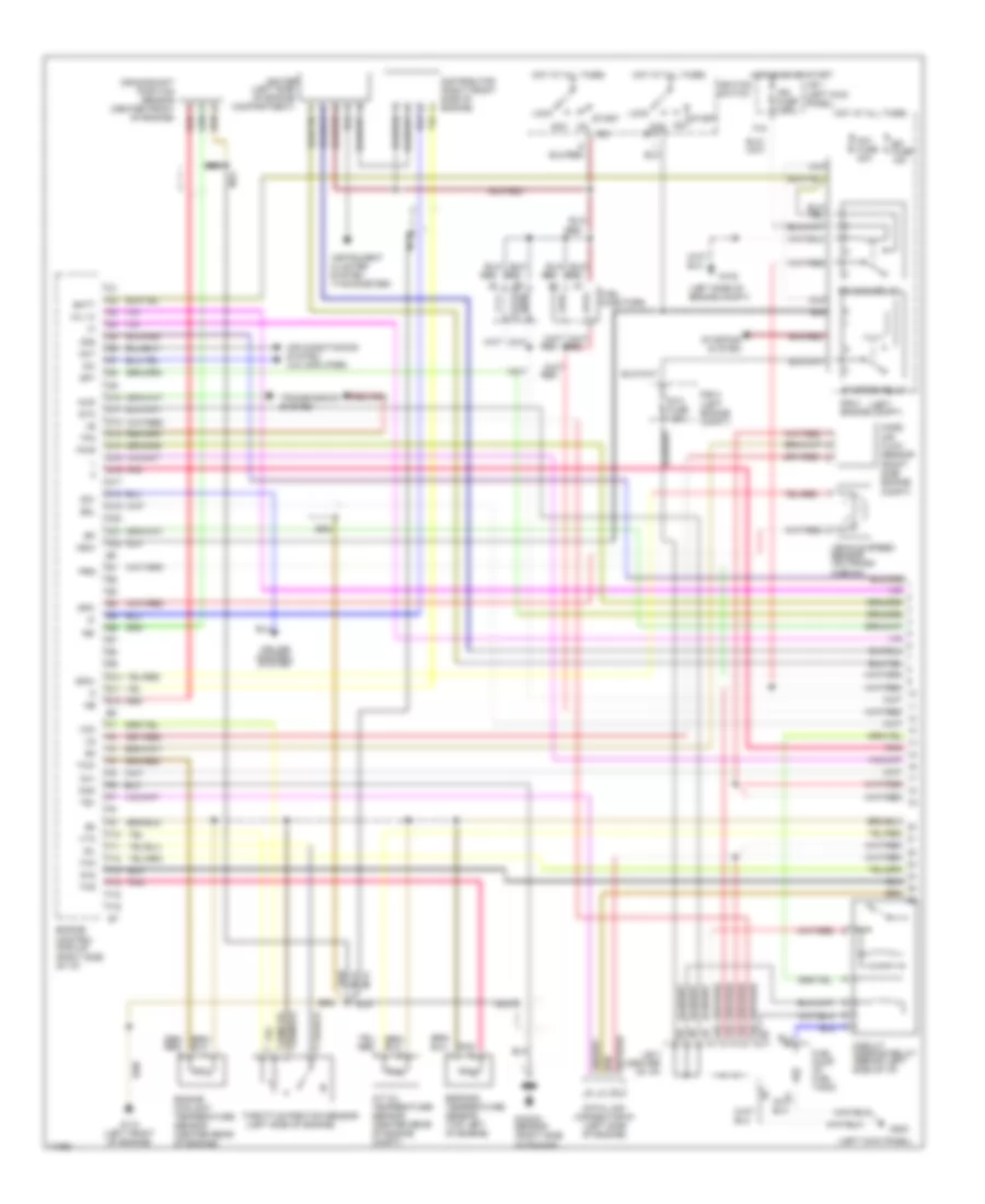
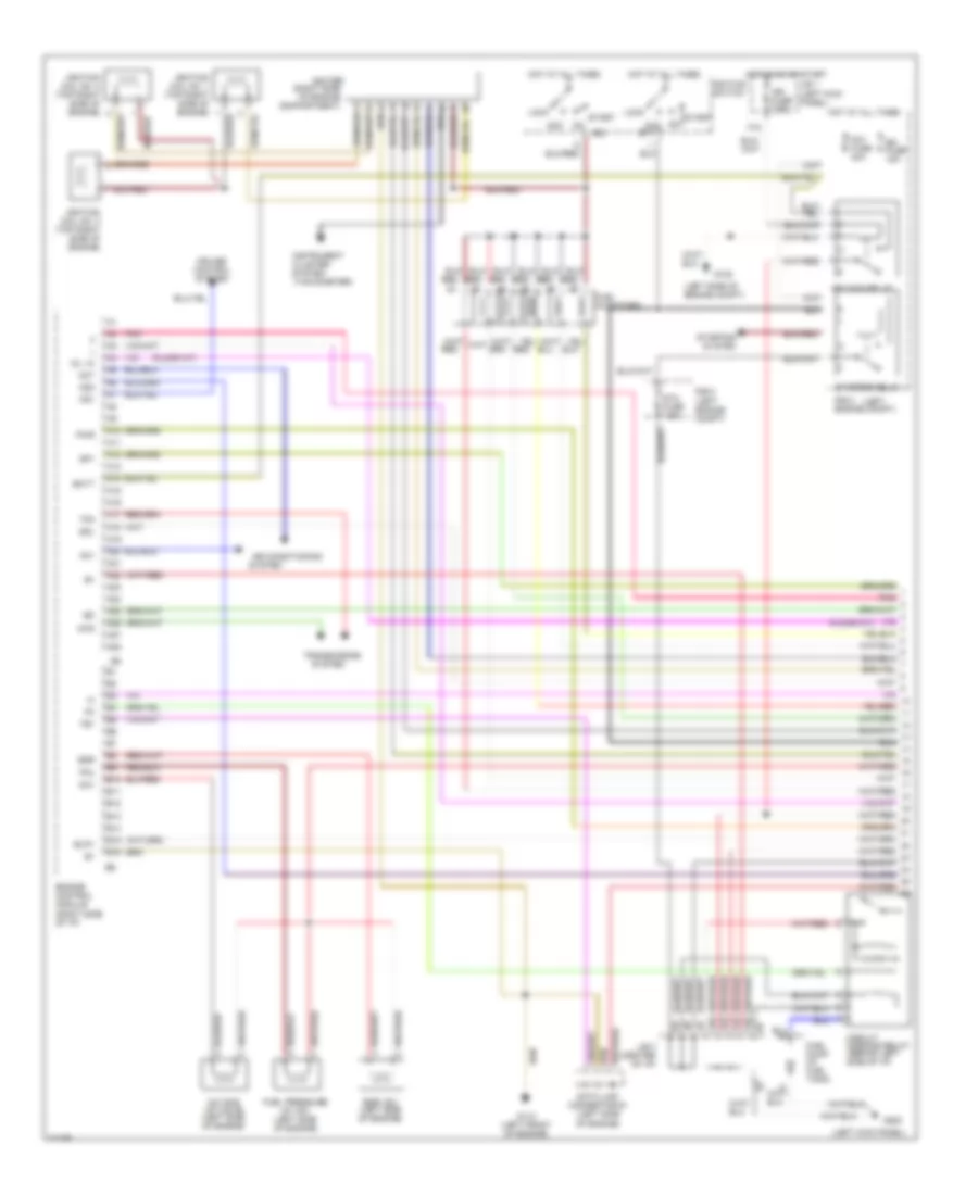
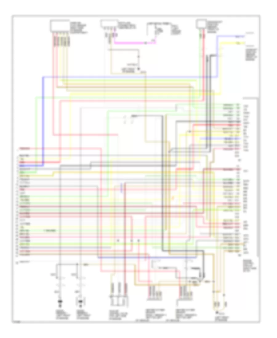
2.7L, Engine Performance Wiring Diagrams, M/T (1 of 2) for Toyota Tacoma 1995
 https://portal-diagnostov.com/license.html
Automotive Electricians Portal FZCO
Automotive Electricians Portal FZCO
https://portal-diagnostov.com/license.html
https://portal-diagnostov.com/license.html
Automotive Electricians Portal FZCO
Automotive Electricians Portal FZCOList of elements for 2.7L, Engine Performance Wiring Diagrams, M/T (1 of 2) for Toyota Tacoma 1995:
- pnk
- (left
- (left engine compt)
- (left kick panel)
- (left side of engine compartment)
- (left side of engine compt)
- (left side of engine)
- (tachometer)
- 12e
- 13e
- 14e
- 15e
- 2.4l (a/t)
- 2.7l, 2.4l (m/t)
- 4wd
- A10
- A11
- A12
- A13
- A14
- A15
- A16
- A17
- A18
- A19
- A20
- A21
- A22
- Acc
- Acc st1
- Aci
- Act
- Air conditioning system (a/c amplifier)
- Am1 fuse 40a
- B10
- B11
- B12
- B13
- B14
- B15
- B16
- Batt
- Circuit opening relay (behind left side of i/p)
- Cluster system
- Crankshaft position sensor (center front of engine)
- Cruise control system
- Data link connector #1 (left side of engine)
- Distributor (right front side of engine)
- Efi fuse 15a
- Efi main relay
- Egr gas temperature sensor (top left of engine)
- Engine control module (right side of i/p)
- Engine coolant temperature sensor (center rear of engine)
- F15
- Fuel injectors
- Fuel pump (in fuel tank)
- G102
- G110 (left front of engine)
- G200
- Hot at all times
- Hot in on or start
- Idl
- Ig2
- Ign fuse 7.5a
- Igniter
- Ignition switch
- Instrument
- J/b 1 (left kick panel)
- J/b 3 (center of i/p)
- Knk
- Knock sensor (right side of engine)
- Lock
- Mass air flow sensor (right side engine compt)
- Nca
- Nca nca
- Nsw
- Od2
- Ox1
- Ox2
- Pnk
- Pwr
- R/b 2
- R/b 2 engine compt)
- Red
- Sdl
- Sp1
- Sta
- Sta fuse 7.5a
- Start
- Starter relay
- Starting
- System
- Te1
- Tha
- Thg
- Throttle position sensor
- Thw
- Transmission system
- Vcc
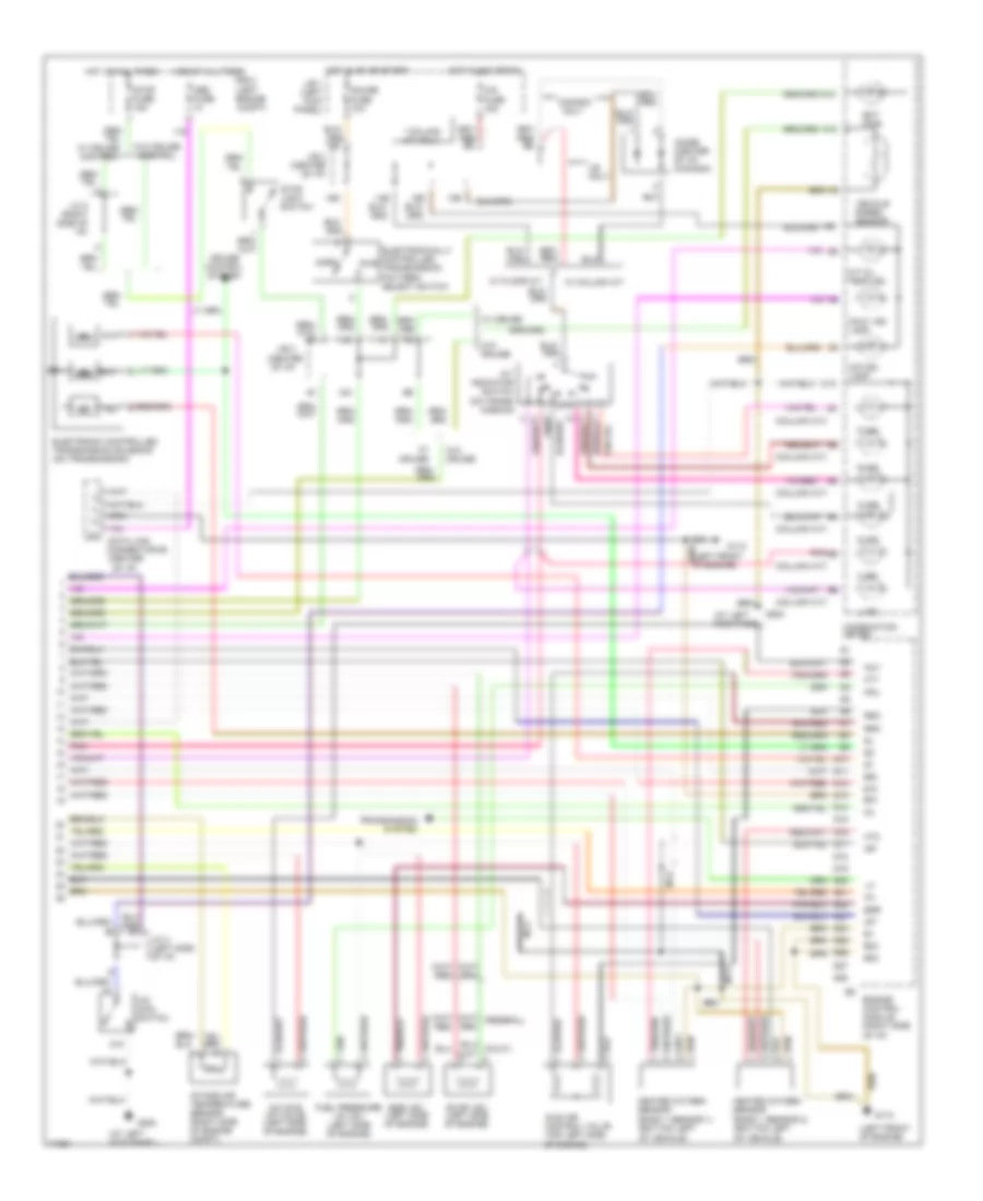
2.7L, Engine Performance Wiring Diagrams, M/T (2 of 2) for Toyota Tacoma 1995
 https://portal-diagnostov.com/license.html
Automotive Electricians Portal FZCO
Automotive Electricians Portal FZCO
https://portal-diagnostov.com/license.html
https://portal-diagnostov.com/license.html
Automotive Electricians Portal FZCO
Automotive Electricians Portal FZCOList of elements for 2.7L, Engine Performance Wiring Diagrams, M/T (2 of 2) for Toyota Tacoma 1995:
- #10
- #20
- (2.4l a/t only)
- (at left kick panel)
- (center of i/p)
- (left front of engine)
- 11c
- 12c
- 13c
- 16d
- 19d
- A/c idle up valve (left side of engine)
- Acv
- C16
- C19
- C21
- C24
- Combination meter
- Data link connector #3 (center of i/p)
- Diode (o/d) (right side of i/p) (2.4l a/t only)
- E01
- E02
- E03
- Ect pwr (2.4l a/t only)
- Egr
- Egr vsv (left side of engine)
- Electronically controlled transmission pattern select switch (2.4l a/t only)
- Engine control module (right side of i/p)
- Evap vsv (left side of engine)
- Fpu
- Fuel pressure up valve (left side of engine)
- G110
- G200
- G200 (at left kick panel)
- Gauge fuse 10a
- Heated oxygen sensor (bank 1 sensor 1) (bottom left of vehicle)
- Heated oxygen sensor (bank 1 sensor 2) (bottom left of vehicle)
- Hot at all times
- Hot in on or start
- Ht1
- Ht2
- Idle air control valve (top left side of engine)
- Igf
- Igt
- Intake air temperature sensor (right side of engine compt)
- J/b 1 (left kick panel)
- J/b 3
- J/b 3 (center of i/p)
- J/c 4 (left side of i/p)
- J/c 8 (right side of i/p)
- Malf. ind. lamp
- Nca
- Ne-
- Norm
- O/d ind. lamp
- O/d main switch (2.4l a/t only)
- O/d solenoid (on trans- mission)
- Obd fuse
- Prg
- Pwr
- R/b 2 (left engine compt)
- Red
- Rsc
- Rso
- Stop fuse 15a
- Stop light switch
- Vehicle speed sensor
- W/ cruise
- W/ cruise control
- W/o cruise
- W/o cruise control
3.4L
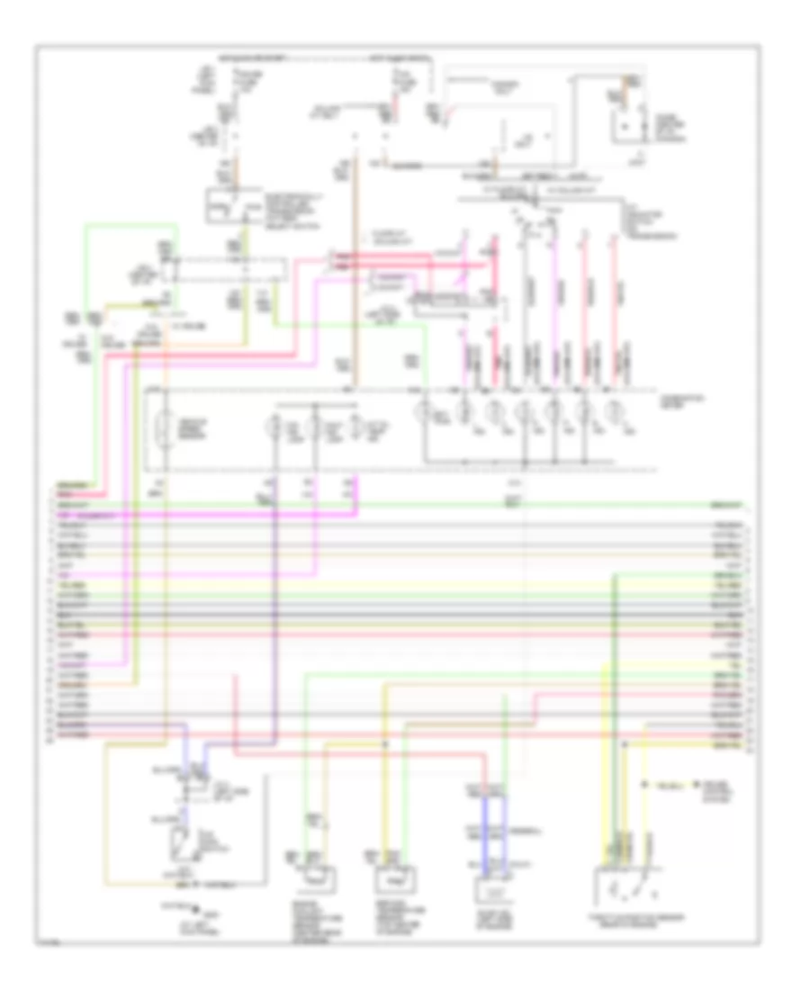
3.4L, Engine Performance Wiring Diagrams, A/T (1 of 3) for Toyota Tacoma 1995
 https://portal-diagnostov.com/license.html
Automotive Electricians Portal FZCO
Automotive Electricians Portal FZCO
https://portal-diagnostov.com/license.html
https://portal-diagnostov.com/license.html
Automotive Electricians Portal FZCO
Automotive Electricians Portal FZCOList of elements for 3.4L, Engine Performance Wiring Diagrams, A/T (1 of 3) for Toyota Tacoma 1995:
- (floor a/t)
- (left
- (left engine compt)
- (left kick panel)
- (left side of engine compt)
- (right side of engine compartment)
- (tachometer)
- 12e
- 13e
- 14e
- 15e
- 4wd
- A/c idle up valve (left side of engine)
- A10
- A11
- A12
- A13
- A14
- A15
- A16
- A17
- A18
- A19
- A20
- A21
- A22
- A23
- A24
- A25
- A26
- A27
- A28
- Ac1
- Acc
- Acc st1
- Act
- Acv
- Air conditioning
- Am1 fuse 40a
- B10
- B11
- B12
- B13
- B14
- B15
- B16
- Batt
- Circuit opening relay (behind left side of i/p)
- Cluster system
- Cruise control system
- Data link connector #1 (left side of engine)
- Efi fuse 15a
- Efi main relay
- Egr
- Egr vsv (left side of engine)
- Engine control module (right side of i/p)
- Evp1
- F15
- Fpu
- Fuel injectors
- Fuel pressure up vsv (left side of engine)
- Fuel pump (in fuel tank)
- G102
- G110 (left front of engine)
- G200
- Hot at all times
- Hot in on or start
- Ig2
- Ign fuse 7.5a
- Igniter
- Ignition coil no. 1 (top right side of engine)
- Ignition coil no. 2 (top right side of engine)
- Ignition coil no. 3 (top right side of engine)
- Ignition switch
- Instrument
- J/b 1 (left kick panel)
- J/b 3 (center of i/p)
- Lock
- Od1
- Od2
- Oil -w
- Pnk
- Pwr
- R/b 2
- R/b 2 engine compt)
- Red
- Sdl
- Sp1
- Sta fuse 7.5a
- Start
- Starter relay
- Starting
- System
- Te1
- Tfn
- Transmission
3.4L, Engine Performance Wiring Diagrams, A/T (2 of 3) for Toyota Tacoma 1995
 https://portal-diagnostov.com/license.html
Automotive Electricians Portal FZCO
Automotive Electricians Portal FZCO
https://portal-diagnostov.com/license.html
https://portal-diagnostov.com/license.html
Automotive Electricians Portal FZCO
Automotive Electricians Portal FZCOList of elements for 3.4L, Engine Performance Wiring Diagrams, A/T (2 of 3) for Toyota Tacoma 1995:
- (at left kick panel)
- (center of i/p)
- (column a/t)
- (column a/t) b3
- (floor a/t)
- (left side
- (rear of engine)
- * **
- 11c
- 13c
- 13d
- 14d
- 16d
- 19d
- A/t indicator switch (on transmission)
- A/t oil temp ind.
- A10
- A12
- B4 (column a/t)
- B5 (column a/t)
- C10
- C13
- Canada
- Cig fuse 15a
- Column a/t
- Column a/t only
- Combination meter
- Cruise
- Cruise control system
- D ind.
- D n
- Diode (center of i/p) (canada)
- Ect pwr
- Egr gas temperature sensor (top center of engine)
- Electronically controlled transmission pattern select switch
- Engine coolant temperature sensor (center rear of engine)
- Evap vsv (left side of engine)
- Floor a/t
- G200
- Gauge fuse 10a
- Hot in acc or on
- Hot in on or start
- Ind.
- J/b 1 (left kick panel)
- J/b 3
- J/b 3 (center of i/p)
- J/c 4
- J/c 4 (left side of i/p)
- L ind.
- Malf. ind. lamp
- N ind.
- Norm
- O/d ind lamp
- O/d main switch
- Of i/p)
- Only
- Pnk
- Pwr
- R ind.
- Throttle position sensor
- Vehicle speed sensor
- W/ column a/t
- W/ cruise
- W/ floor a/t
- W/o
- W/o cruise
- P ind.
3.4L, Engine Performance Wiring Diagrams, A/T (3 of 3) for Toyota Tacoma 1995
 https://portal-diagnostov.com/license.html
Automotive Electricians Portal FZCO
Automotive Electricians Portal FZCO
https://portal-diagnostov.com/license.html
https://portal-diagnostov.com/license.html
Automotive Electricians Portal FZCO
Automotive Electricians Portal FZCOList of elements for 3.4L, Engine Performance Wiring Diagrams, A/T (3 of 3) for Toyota Tacoma 1995:
- #10
- #20
- #30
- #40
- #50
- #60
- (center of i/p)
- (left front of engine)
- A/t oil temperature sensor (center rear of engine compt)
- C15
- Camshaft position sensor (front of engine)
- Crankshaft position sensor (front of engine)
- Cruise control system
- D18
- D19
- D20
- D21
- D28
- D30
- D31
- Data link connector #3 (center of i/p)
- E01
- E02
- E03
- Electronic controlled transmission solenoid (on transmission)
- Engine control module (right side of i/p)
- G110
- Heated oxygen sensor (bank 1 sensor 1) (bottom left of vehicle)
- Heated oxygen sensor (bank 1 sensor 2) (bottom left of vehicle)
- Hot at all times
- Ht1
- Ht2
- Idl
- Idle air control valve (top left side of engine)
- Igf
- Igt1
- Igt2
- Igt3
- J/b 3
- J/c 8 (right side of i/p)
- Knk1
- Knk2
- Knock sensor 1 (left front of engine)
- Knock sensor 2 (left front of engine)
- Mass air flow sensor (right side of engine compartment)
- Nca
- Ne-
- Nsw
- Obd fuse
- Oil
- Ox1
- Ox2
- R/b 2 (left engine compt)
- Red
- Rsc
- Rso
- Sp2+
- Sp2-
- Sta
- Stop fuse 15a
- Stop light switch
- Tha
- Thg
- Thw
- Transmission system
- Vcc
- Vehicle speed sensor (on trans- mission)
- Vta
- W/ cruise control
- W/o cruise control
3.4L, Engine Performance Wiring Diagrams, M/T (1 of 3) for Toyota Tacoma 1995
 https://portal-diagnostov.com/license.html
Automotive Electricians Portal FZCO
Automotive Electricians Portal FZCO
https://portal-diagnostov.com/license.html
https://portal-diagnostov.com/license.html
Automotive Electricians Portal FZCO
Automotive Electricians Portal FZCOList of elements for 3.4L, Engine Performance Wiring Diagrams, M/T (1 of 3) for Toyota Tacoma 1995:
- (left
- (left engine compt)
- (left kick panel)
- (left side of engine compt)
- (right side of engine compartment)
- (tachometer)
- 12e
- 13e
- 14e
- 15e
- 4wd
- A/c idle up valve (left side of engine)
- Acc
- Acc st1
- Aci
- Act
- Air conditioning system
- Am1 fuse 40a
- Batt
- Circuit opening relay (behind left side of i/p)
- Cluster system
- Data link connector #1 (left side of engine)
- Detection switch
- E03
- E10
- E11
- E12
- E13
- E14
- E15
- E16
- E17
- E18
- E19
- E20
- E21
- E22
- Efi fuse 15a
- Efi main relay
- Egr vsv (left side of engine)
- Engine control module (right side of i/p)
- F10
- F11
- F12
- F15
- Fuel injectors
- Fuel pressure up vsv (left side of engine)
- Fuel pump (in fuel tank)
- G102
- G110 (left front of engine)
- G200
- Hot at all times
- Hot in on or start
- Ht1
- Ht2
- Ig2
- Ign fuse 7.5a
- Igniter
- Ignition coil no. 1 (top right side of engine)
- Ignition coil no. 2 (top right side of engine)
- Ignition coil no. 3 (top right side of engine)
- Ignition switch
- Instrument
- J/b 1 (left kick panel)
- J/b 3 (center of i/p)
- Lock
- Ne-
- R/b 2
- R/b 2 engine compt)
- Red
- Sdl
- Sp1
- Sta
- Sta fuse 7.5a
- Start
- Starter relay
- Starting
- System
3.4L, Engine Performance Wiring Diagrams, M/T (2 of 3) for Toyota Tacoma 1995
 https://portal-diagnostov.com/license.html
Automotive Electricians Portal FZCO
Automotive Electricians Portal FZCO
https://portal-diagnostov.com/license.html
https://portal-diagnostov.com/license.html
Automotive Electricians Portal FZCO
Automotive Electricians Portal FZCOList of elements for 3.4L, Engine Performance Wiring Diagrams, M/T (2 of 3) for Toyota Tacoma 1995:
-
-
- (at left kick panel)
- (center of i/p)
- (rearof engine)
- 17d
- 19d
- C10
- Combination meter
- Cruise
- Cruise control system
- Egr gas temperature sensor (top right of engine)
- Engine coolant temperature sensor (center rear of engine)
- Evap vsv (left side of engine)
- G200
- Gauge fuse 10a
- Hot at all times
- Hot in on or start
- J/b 1 (left kick panel)
- J/b 3
- J/b 3 (center of i/p)
- J/c 8 (right side of i/p)
- Malf. ind. lamp
- R/b 2 (left engine compt)
- Stop fuse 15a
- Stop light switch
- Throttle position sensor
- Vehicle speed sensor
- W/ cruise
- W/ cruise control
- W/o
- W/o cruise
- W/o cruise control
3.4L, Engine Performance Wiring Diagrams, M/T (3 of 3) for Toyota Tacoma 1995
 https://portal-diagnostov.com/license.html
Automotive Electricians Portal FZCO
Automotive Electricians Portal FZCO
https://portal-diagnostov.com/license.html
https://portal-diagnostov.com/license.html
Automotive Electricians Portal FZCO
Automotive Electricians Portal FZCOList of elements for 3.4L, Engine Performance Wiring Diagrams, M/T (3 of 3) for Toyota Tacoma 1995:
- #10
- #20
- #30
- #40
- #50
- #60
- (left front of engine)
- Acv
- Camshaft position sensor (front of engine)
- Crankshaft position sensor (front of engine)
- Data link connector #3 (center of i/p)
- E01
- Egr
- Engine control module (right side of i/p)
- Evp1
- Fpu
- G110
- G15
- G16
- H15
- H16
- H20
- Heated oxygen sensor (bank 1 sensor 1) (bottom left
- Heated oxygen sensor (bank 1 sensor 2) (bottom left
- Hot at all times
- Idl
- Idle air control valve (top left side of engine)
- Igf
- Igt1
- Igt2
- Igt3
- Knk1
- Knk2
- Knock sensor 1 (left front of engine)
- Knock sensor 2 (left front of engine)
- Mass air flow sensor (right side of engine compartment)
- Nca
- Obd fuse
- Of vehicle)
- Ox1
- Ox2
- R/b 2 (left engine compt)
- Red
- Rsc
- Rso
- Te1
- Tha
- Thg
- Thw
- Vcc
- Vta

 Čeština
 Dansk
Dansk Deutsch
 Ελληνικά
 English
 English
 Español
 Suomi
Suomi Français
 Français
 עברית
עברית Hrvatski
 Magyar
 Italiano
 日本語
日本語 한국어
한국어 Nederlands
 Polski
 Português
 Português
 Română
 Русский
 Slovenčina
 Slovenščina
 Svenska
 Türkçe
