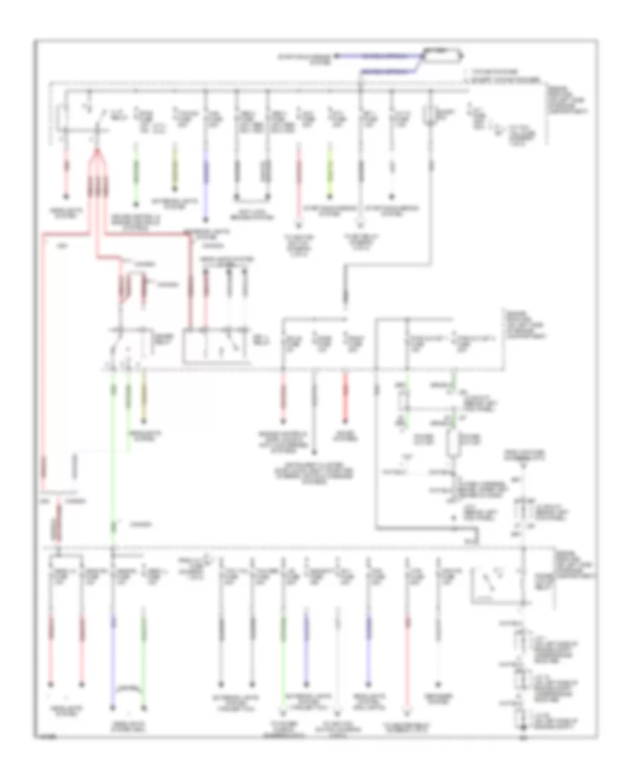
POWER DISTRIBUTION
Power Distribution Wiring Diagram, Access/Standard Cab (1 of 2) for Toyota Tundra 2004
 https://portal-diagnostov.com/license.html
Automotive Electricians Portal FZCO
Automotive Electricians Portal FZCO
https://portal-diagnostov.com/license.html
https://portal-diagnostov.com/license.html
Automotive Electricians Portal FZCO
Automotive Electricians Portal FZCO
List of elements for Power Distribution Wiring Diagram, Access/Standard Cab (1 of 2) for Toyota Tundra 2004:
- (4.7l) (3.4l)
- (abs) (vsc)
- Abs 2 fuse 40a 50a
- Abs 3 fuse 40a 50a
- Alt fuse 140a 100a
- Alt s fuse 7.5a
- Am 1 fuse 40a
- Am 2 fuse 30a
- Anti-lock brakes system
- Battery
- Canada
- Center of dash)
- Cruise control & engine controls systems
- Defogger system
- Dimmer relay
- Dome fuse 10a
- Drl 4 relay
- Ecu b fuse 5a
- Efi 1 fuse 15a
- Engine controls, door locks & anti-lock brakes systems
- Engine room r/b (on left side of engine compartment)
- Etcs fuse 10a 15a
- Except towing package
- Exterior lights system
- Exterior lights system (trailer tow)
- Fog fuse 20a
- From acc fuse (diagram 2 of 2)
- From alt a fuse (diagram 1 of 2)
- H lp relay
- Haz fuse 20a
- Head lh fuse 10a
- Head ll fuse 10a
- Head rh fuse 10a
- Head rl fuse 10a
- Headlights system
- Headlights system (drl)
- Headlights system (fog lights)
- Headlights system w/ drl
- Htr fuse 50a
- Instrument cluster, door locks, body computer, interior lights & warnings systems
- J/b fuse 50a
- J/c 1 (on left side of engine compt, under engine room r/b)
- J/c 18 (on left side of engine compt, under engine room r/b)
- J/c 25 (on left side of engine compt)
- J/c 26 & 27 (behind left kick panel)
- J/c 3 (behind left kick panel)
- J26
- J27
- Mir htr fuse 15a
- Power outlet
- Power outlet relay
- Pwr outlet 1 fuse 15a
- Pwr outlet 2 fuse 20a
- Radio fuse 20a
- Red
- Short pin
- Sound systems
- St3 fuse 30a
- Starting/charging system
- Sub batt fuse 30a
- To efi relay (diagram 2 of 2)
- To heater relay (diagram 2 of 2)
- To ignition switch (diagram 2 of 2)
- To ignition switch (diagram 2 of 2)
- To power fuse 30 (diagram 2 of 2)
- To tow tail fuse (diagram 1 of 2)
- Tow brk fuse 30a
- Tow tail fuse 30a
- Towing fuse 30a
- Towing package
- Usa
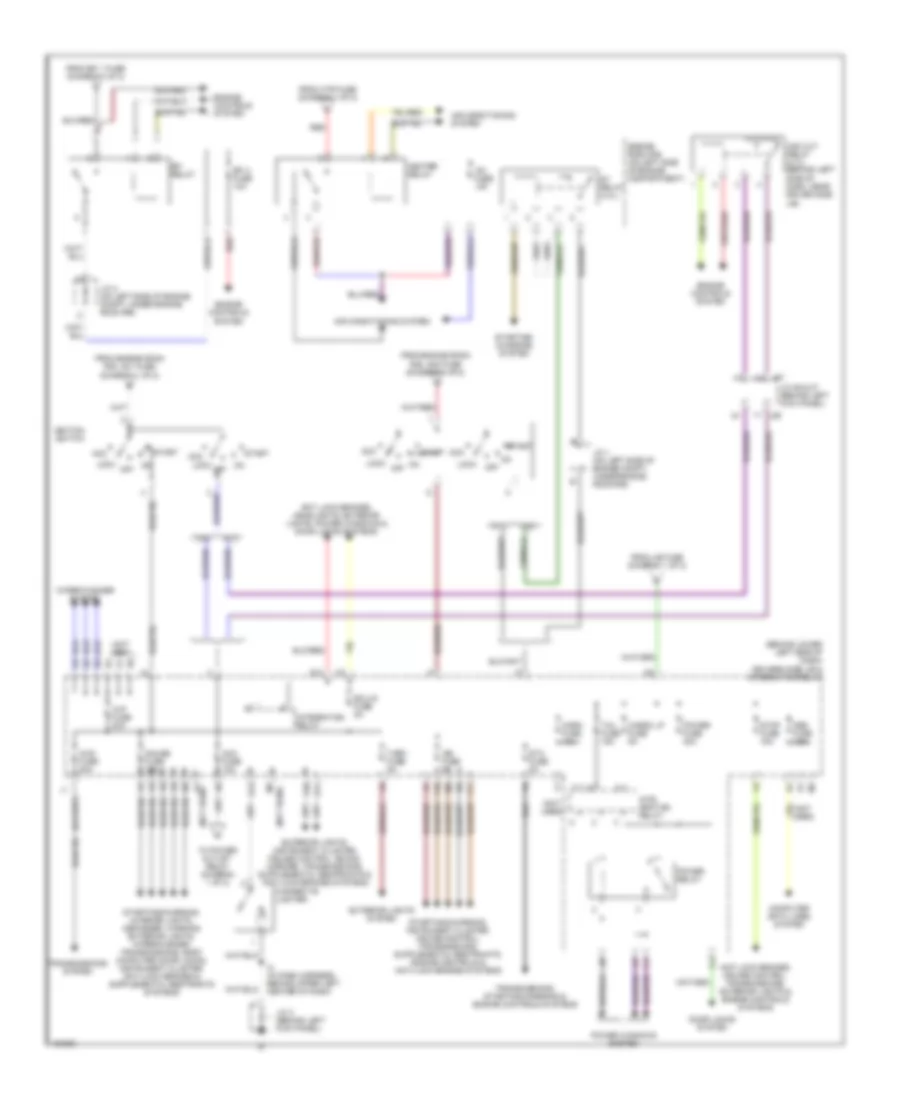
Power Distribution Wiring Diagram, Access/Standard Cab (2 of 2) for Toyota Tundra 2004
 https://portal-diagnostov.com/license.html
Automotive Electricians Portal FZCO
Automotive Electricians Portal FZCO
https://portal-diagnostov.com/license.html
https://portal-diagnostov.com/license.html
Automotive Electricians Portal FZCO
Automotive Electricians Portal FZCOList of elements for Power Distribution Wiring Diagram, Access/Standard Cab (2 of 2) for Toyota Tundra 2004:
- (behind lower left side of dash) drivers side j/b & integration relay
- (not used)
- 3.4l
- 4.7l
- 4wd fuse 20a
- A/c fuse 10a
- Acc
- Acc cut relay (4.7l) (behind left side of dash, near driver side
- Acc fuse 15a
- Air conditioning system
- Anti lock brakes, cruise control, transmissions, exterior lights & engine controls systems
- Anti lock brakes, headlights, exterior lights, power windows & door locks systems
- Cargo lp fuse 5a
- Cigarette lighter
- Computer data lines system
- Door locks system
- Ecu ig fuse 5a
- Efi 2 fuse 10a
- Efi relay
- Engine controls system
- Engine room r/b (on left side of engine compartment)
- Exterior lights system
- F10
- F11
- From efi 1 fuse (diagram 1 0f 2)
- From engine room r/b, am1 fuse (diagram 1 of 2)
- From engine room r/b, am2 fuse (diagram 1 of 2)
- From htr fuse (diagram 1 of 2)
- From j/b fuse (diagram 1 of 2)
- G10
- G11
- G12
- G13
- Gauge fuse 10a
- Heater relay
- Horn fuse 10a
- I2 (in dash harness, behind upper left center of dash)
- Ign fuse 5a
- Ignition switch
- Inte gration relay
- Integration relay
- J/b)
- J/c 1 (on left side of engine compt, under engine room r/b)
- J/c 2 (on left side of engine compt, under engine room r/b)
- J/c 26 & 27 (behind left kick panel)
- J/c 3 (behind left kick panel)
- J26
- J27
- Lock
- Obd fuse 7.5a
- Off
- Power fuse 30a
- Power relay
- Power windows system
- Red
- St relay (3.4l)
- Sta fuse 5a
- Start
- Starting/ charging system
- Stop fuse 15a
- Tail fuse 15a
- To power outlet relay (diagram 1 of 2)
- Transmissions system
- Transmissions, starting/charging & engine controls systems
- Turn fuse 5a
- Wip fuse 20a
- Wiper/washer system
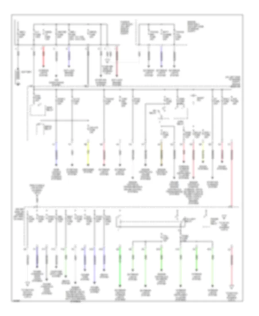
Power Distribution Wiring Diagram, Double Cab (1 of 2) for Toyota Tundra 2004
 https://portal-diagnostov.com/license.html
Automotive Electricians Portal FZCO
Automotive Electricians Portal FZCO
https://portal-diagnostov.com/license.html
https://portal-diagnostov.com/license.html
Automotive Electricians Portal FZCO
Automotive Electricians Portal FZCOList of elements for Power Distribution Wiring Diagram, Double Cab (1 of 2) for Toyota Tundra 2004:
- (on left side of engine compt) engine room j/b
- (w/ vcs) (w/o vcs)
- Abs 1 fuse 50a 30a
- Abs 2 fuse 60a
- Air conditioning system
- Alt fuse 140a
- Alt-s fuse 7.5a
- Am1 fuse 40a
- Am2 fuse 25a
- Anti-lock brakes system
- Batt charge fuse 30a
- Battery
- Cargo lp fuse 7.5a
- Computer data lines system
- Cruise control, engine controls & transmissions systems
- Defog fuse 40a
- Defog relay
- Defogger system
- Dome fuse 10a
- Door 2 fuse 30a
- Door locks & power windows systems
- Driver side j/b (under left end of dash)
- E12
- E18
- Ecu b fuse 7.5a
- Efi 1 fuse 20a
- Efi 2 fuse 10a
- Efi relay
- Engine controls & cruise control systems
- Engine controls & exterior lights system
- Engine controls system
- Engine controls, exterior lights, cruise control, transmissions & anti-lock brakes systems
- Engine controls, transmissions & cruise control systems
- Engine controls, warning, interior lights, exterior lights, power windows, door locks & anti-lock brakes systems
- Engine room r/b 3 (on 0left side of engine compt)
- Etcs fuse 10a
- Exterior lights & interior lights systems
- Exterior lights system
- F13
- F17
- F18
- From fusible link block (diagram 1 of 2)
- Fusible link block (on left side of engine compt)
- G15
- G16
- H10
- Head relay
- Heater fuse 50a
- Horn fuse 10a
- Horn relay
- Interior lights & instrument cluster systems
- Interior lights system
- Mian fuse 40a
- Mir htr fuse 15a
- Obd fuse 7.5a
- Panel fuse 7.5a
- Power main relay
- Power tops system
- Power windows & door locks systems
- Power windows system
- Pwr 1 fuse 25a
- Pwr 2 fuse 25a
- Pwr 5 fuse 30a
- Pwr seat fuse 30a
- Rad 1 fuse 25a
- Rad 3 fuse 20a
- Red
- Seat htr fuse 15a
- Seats system
- Short pin
- Sound systems
- St fuse 30a
- Starting/ charging system
- Stop fuse 15a
- Sun roof fuse 25a
- Tail fuse 15a
- Taillight relay
- To ac inv fuse (diagram 2 of 2)
- To driver side j/b (diagram 1 of 2)
- To ignition switch (diagram 2 of 2)
- Towing brk fuse 30a
- Towing fuse 30a
- Towing tail fuse 30a
- Turn haz fuse 20a
- Warning, interior lights & instrument cluster systems
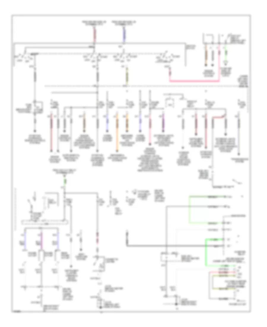
Power Distribution Wiring Diagram, Double Cab (2 of 2) for Toyota Tundra 2004
 https://portal-diagnostov.com/license.html
Automotive Electricians Portal FZCO
Automotive Electricians Portal FZCO
https://portal-diagnostov.com/license.html
https://portal-diagnostov.com/license.html
Automotive Electricians Portal FZCO
Automotive Electricians Portal FZCOList of elements for Power Distribution Wiring Diagram, Double Cab (2 of 2) for Toyota Tundra 2004:
- (at right rear
- (behind right end of dash) in
- (diagram 1 of 2)
- (under left end of dash)
- (under left end of dash) driver side j/b
- 4wd fuse 20a
- Ac inv fuse 15a
- Ac1
- Ac2
- Acc
- Acc cut relay (behind left kick panel)
- Acc relay
- Am1
- Am2
- Back-up light relay
- Body computer system
- Cig fuse 15a
- Cigarette lighter
- Corner of cab)
- D10
- D11
- D12
- Defogger & air conditioning systems
- Defogger, seats & air conditioning systems
- Driver side j/b (under left end of dash)
- Driver side r/b
- E10
- E17
- E20
- Ecu ig fuse 10a
- Engine controls system
- Engine controls, transmissions, cruise control & anti-lock brakes systems
- Exterior lights, instrument cluster & air conditioning systems
- Exterior lights, interior lights, power windows, anti-lock brakes & door locks systems
- F12
- Fog fuse 15a
- Fog light relay
- From acc cut relay (diagram 2 of 2)
- From driver side j/b (diagram 1 of 2)
- Fuse box (behind right kick panel)
- G11
- Gauge fuse 15a
- H11
- Htr fuse 10a
- Ig1
- Ig2
- Ign1 fuse 10a
- Ign2 fuse 20a
- Ignition switch
- Instrument cluster & power tops systems
- Instrument cluster, mirrors & sound systems
- Interior lights, power windows & door locks systems
- Inv
- Inverter
- Ipo
- J/c 45 (behind left side of dash)
- J/c 52 (behind center of dash)
- J/c 58 (behind right side of dash)
- Lock
- Main relay
- Main switch
- Off
- Pnk
- Power outlet
- Power outlet fuse 15a
- Rad 2 fuse 7.5a
- Rear power outlet
- Relay
- St fuse 7.5a
- St2
- Start
- Starting/ charging & engine controls systems
- Starting/ charging & instrument cluster systems
- Starting/ charging system
- Sub j/b 3 (behind center of dash)
- To driver side j/b (diagram 2 of 2)
- To power
- Transmissions system
- Voltage inverter
- Wip fuse 25a
- Wiper/ washer system
- Wsh fuse 25a

 Čeština
 Dansk
Dansk Deutsch
 Ελληνικά
 English
 English
 Español
 Suomi
Suomi Français
 Français
 עברית
עברית Hrvatski
 Magyar
 Italiano
 日本語
日本語 한국어
한국어 Nederlands
 Polski
 Português
 Português
 Română
 Русский
 Slovenčina
 Slovenščina
 Svenska
 Türkçe
