RADIO
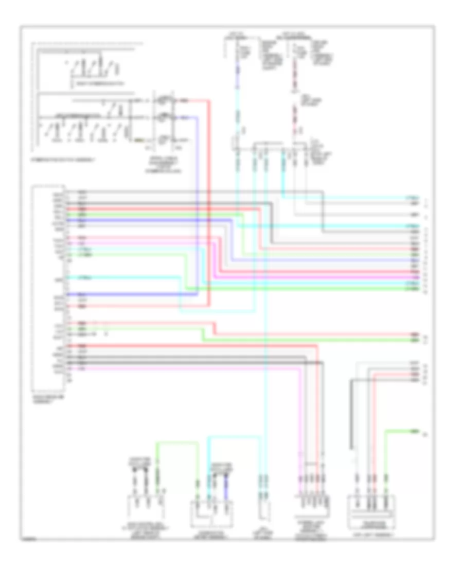
Radio Wiring Diagram, with Built-in Amplifier (1 of 2) for Toyota 4Runner SR5 2010

List of elements for Radio Wiring Diagram, with Built-in Amplifier (1 of 2) for Toyota 4Runner SR5 2010:
- A50
- A87
- A90
- Acc fuse 7.5a
- Agnd
- Ali
- Alo
- Amp fuse 30a
- Ari
- Aro
- Asgn
- Au1
- Au2
- Auxi
- Auxo
- B17
- B20
- Canh
- Canl
- Combination meter assembly
- Computer data lines system
- Driver side r/b assembly (left end of dash)
- Eau
- Engine room r/b assembly (left side of engine compt)
- F23
- G1 (right end of dash)
- G13
- G14
- Hot at all times
- Hot w/ acc relay energized
- Il+2
- Il-2
- Interior lights system
- J/b 4 (left side of dash)
- J/c g13 & g14 (top left g14 side of dash)
- J/c g13 & g14 (top left side of dash)
- Left steering switch
- Macc
- Min+
- Min-
- Mode
- Nca
- Off hook
- On hook
- Pnk
- Radio receiver assembly
- Red
- Right steering switch
- Seek+
- Seek-
- Sgnd
- Skid control ecu w/ actuator assembly (left rear of engine compt)
- Sns2
- Sp1
- Spd
- Spiral cable sub-assembly (top of steering column)
- Steering pad switch assembly (if equipped)
- Stereo jack adapter assembly 1 (w/o multi-media interface)
- Sw+
- Sw-
- Sw1
- Sw2
- Swg
- Voice
- Volume+
- Volume-
- Woofer speaker switch
- Z11
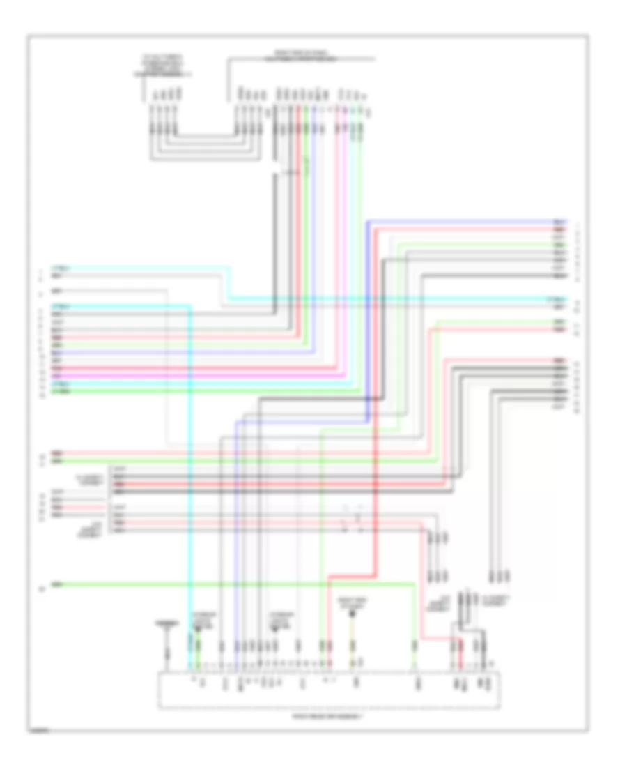
Radio Wiring Diagram, with Built-in Amplifier (2 of 2) for Toyota 4Runner SR5 2010
List of elements for Radio Wiring Diagram, with Built-in Amplifier (2 of 2) for Toyota 4Runner SR5 2010:
- (center right of dash) dcm (telematics transceiver)
- (or pnk)
- Acc
- Cdl+
- Cdl-
- Cdr+
- Cdr-
- Csld
- Fl+
- Fl-
- Fr+
- Fr-
- G1 (right end of dash)
- G11
- G27
- Gnd
- Ill+
- Ill-
- Interior lights system
- Left eq relay
- Left front speaker assembly 1
- Left front speaker assembly 2
- Left rear speaker assembly 1
- Left rear speaker assembly 2
- Macc
- Mci+
- Mci-
- Mco+
- Mco-
- Mcvd
- Multi-media interface ecu (if equipped) (right end of dash)
- Mut1
- Mute
- Nca
- Passenger room r/b assembly (right end of dash)
- Pnk
- Radio receiver assembly
- Red
- Right eq relay
- Right front speaker assembly 1
- Right front speaker assembly 2
- Right rear speaker assembly 1
- Right rear speaker assembly 2
- Rl+
- Rl-
- Rr+
- Rr-
- Sgnd
- Sns2
- Spi+
- Spi-
- Spo+
- Spo-
- Stereo jack adapter assembly 2
- System & w/o safety connect
- Telephone microphone
- Tx1+
- Tx1-
- Txm+
- Txm-
- Ud1+
- Udi-
- Udo+
- Udo-
- Uesg
- Ujsg
- Ulo+
- Ulo-
- Up1
- Upo
- Uro+
- Uro-
- Usd1
- W/ safety connect
- W/o safety connect
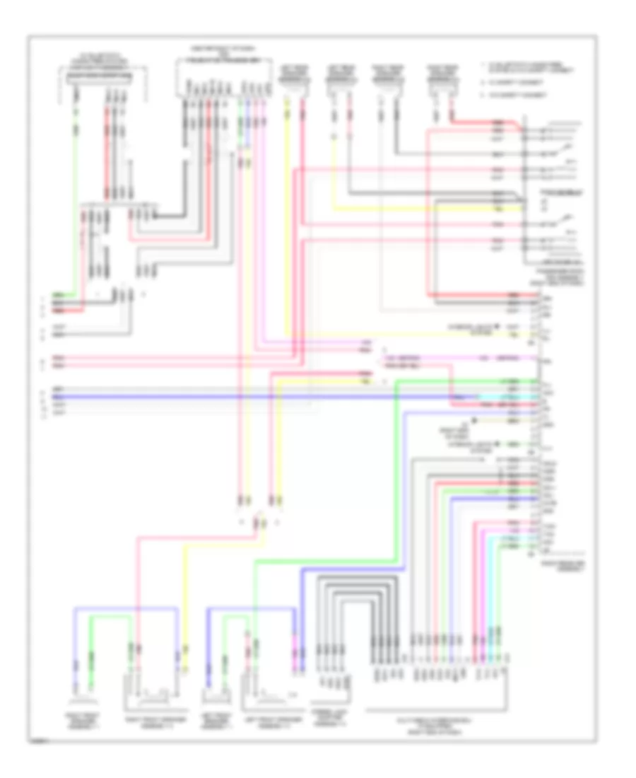
Radio Wiring Diagram, with Navigation with Separate Amplifier (1 of 3) for Toyota 4Runner SR5 2010
List of elements for Radio Wiring Diagram, with Navigation with Separate Amplifier (1 of 3) for Toyota 4Runner SR5 2010:
- A50
- A64
- A66
- A87
- A90
- A91
- A95
- Acc
- Acc fuse 7.5a
- Agnd
- Ali
- Alo
- Ari
- Aro
- Asgn
- Au1
- Au2
- Auxi
- Auxo
- B17
- B20
- B24
- B33
- B35
- B39
- B57
- B59
- C20
- C23
- C31
- Canh
- Canl
- Cdl+
- Cdl-
- Cdr+
- Cdr-
- Combination meter assembly
- Computer data lines system
- Csld
- D17
- Driver room r/b assembly (left end of dash)
- Driver side r/b assembly (left end of dash)
- Eau
- Ecu ig 1 fuse 10a
- Ecu ig 2 fuse 10a
- Engine room r/b assembly (left side of engine compt)
- F23
- G13
- G14
- G16
- G17
- G18
- G19
- Gnd
- Hot at all times
- Hot w/ acc relay energized
- Hot w/ ig 1 relay energized
- Ivo+
- Ivo-
- J/b 4 (left side of dash)
- J/b 5 (center of dash)
- J/c b48 (right side of dash)
- J/c g13 & g14 (top left side of dash)
- Left steering switch
- Macc
- Map light assembly
- Mco+
- Mco-
- Mode
- Mute
- Navigation receiver assembly (center of dash)
- Nca
- Off hook
- On hook
- Park/neutral position switch (right side of transmission)
- Parking brake switch assembly (upper left end of dash)
- Pkb
- Pnk
- Rad 1 fuse 10a
- Red
- Rev
- Right steering switch
- Seek+
- Seek-
- Skid control ecu w/ actuator assembly (left rear of engine compt)
- Sld1
- Sns2
- Sp1
- Spd
- Spiral cable sub-assembly (top of steering column)
- Steering pad switch assembly
- Stereo jack adapter assembly 1 (w/o multimedia interface ecu)
- Sw1
- Sw2
- Swg
- Telephone microphone
- Tx1+
- Tx1-
- Txm+
- Txm-
- Txo+
- Txo-
- Voice
- Volume+
- Volume-
- Z11
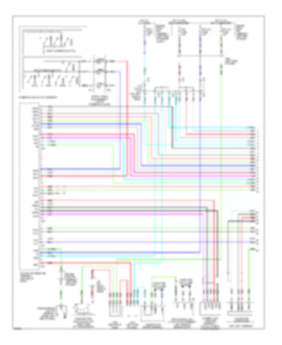
Radio Wiring Diagram, with Navigation with Separate Amplifier (2 of 3) for Toyota 4Runner SR5 2010
List of elements for Radio Wiring Diagram, with Navigation with Separate Amplifier (2 of 3) for Toyota 4Runner SR5 2010:
- (rear end of center console) stereo component tuner assembly
- (right end of dash) g1
- (right end of dash) multi-media interface ecu
- Acc
- Antenna
- Atx+
- Atx-
- Ca+
- Canh
- Canl
- Cb+
- Cgnd
- Computer data lines system
- Connect
- Cv+
- Cv-
- Flo+
- Flo-
- Fro+
- Fro-
- G1 (right end of dash)
- G11
- G20
- G23
- G24
- G25
- G27
- G28
- Gnd
- Gps antenna
- Ill+
- Ill-
- Interior lights system
- Macc
- Min+
- Min-
- Mut1
- Mut2
- Mute
- Navigation receiver assembly (center of dash)
- Nca
- Pnk
- Rear television camera assembly (if equipped) (center of tailgate)
- Red
- Red w/o safety nca
- Sgnd
- Sld
- Sns2
- Stereo jack adapter assembly 2
- Tx+
- Tx-
- Tx1+
- Tx1-
- Tx2+
- Tx2-
- Txo+
- Txo-
- Udi+
- Udi-
- Udo+
- Udo-
- Uesg
- Ujsg
- Uli+
- Uli-
- Ulo+
- Ulo-
- Up1
- Upo
- Uri+
- Uri-
- Uro+
- Uro-
- Usd1
- Usd2
- W/ safety connect
- W/o safety connect
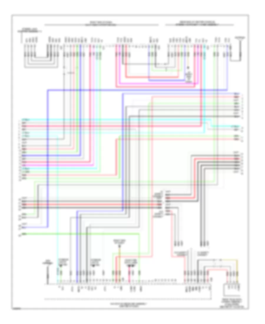
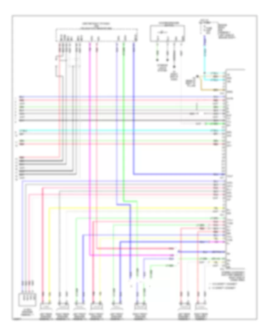
Radio Wiring Diagram, with Navigation with Separate Amplifier (3 of 3) for Toyota 4Runner SR5 2010
List of elements for Radio Wiring Diagram, with Navigation with Separate Amplifier (3 of 3) for Toyota 4Runner SR5 2010:
- (center right of dash) dcm (telematics transceiver)
- (or pnk)
- +b2
- Acc
- Amp fuse 30a
- Engine room r/b assembly (left side of engine compt)
- Fl+
- Fl-
- Fr+
- Fr-
- G1 (right end of dash)
- Gnd
- Gnd2
- Hot at all times
- Il+2
- Il-2
- Int+
- Int-
- Interior lights system
- Left front speaker assembly 1
- Left front speaker assembly 2
- Left rear speaker assembly 1
- Left rear speaker assembly 2
- Mci+
- Mci-
- Mco+
- Mco-
- Mcvd
- Mute
- N11
- N12
- N13
- N14
- N2 (base of right "d" pillar)
- Nca
- Pnk
- R-l+
- R-l-
- R-r+
- R-r-
- Red
- Right front speaker assembly 1
- Right front speaker assembly 2
- Right rear speaker assembly 1
- Right rear speaker assembly 2
- Rl+
- Rl-
- Rr+
- Rr-
- Sgnd
- Sld
- Spd
- Spi+
- Spi-
- Spo+
- Spo-
- Stereo component amplifier assembly (right side of cargo area)
- Sw+
- Sw-
- Tmut
- Twl+
- Twl-
- Twr+
- Twr-
- Tx+
- Tx-
- W/ box speaker assembly 1
- W/ safety connect
- W/o safety connect
- Wf-
- Wf1+
- Wf1-
- Wf2+
- Wf2-
- Woofer speaker switch
Radio Wiring Diagram, without Navigation with Separate Amplifier (1 of 3) for Toyota 4Runner SR5 2010
List of elements for Radio Wiring Diagram, without Navigation with Separate Amplifier (1 of 3) for Toyota 4Runner SR5 2010:
- A50
- A87
- A90
- Acc
- Acc fuse 7.5a
- Agnd
- Ali
- Alo
- Ari
- Aro
- Asgn
- Au1
- Au2
- Auxi
- Auxo
- B17
- B20
- Canh
- Canl
- Cdl+
- Cdl-
- Cdr+
- Cdr-
- Combination meter assembly
- Computer data lines system
- Csld
- Driver room r/b assembly (left end of dash)
- Eau
- Engine room r/b assembly (left side of engine compt)
- F23
- G13
- G14
- Gnd
- Hot at all times
- Hot w/ acc relay energized
- Ivo+
- Ivo-
- J/b 4 (left side of dash)
- J/c g13 & g14 (top left g13
- Left steering switch
- Macc
- Map light assembly
- Mco+
- Mco-
- Mode
- Mute
- Nca
- Off hook
- On hook
- Pnk
- Rad 1 fuse 10a
- Radio receiver assembly
- Red
- Right steering switch
- Seek+
- Seek-
- Side of dash)
- Skid control ecu w/ actuator assembly (left rear of engine compt)
- Sld1
- Sns2
- Sp1
- Spd
- Spiral cable sub-assembly (top of steering column)
- Steering pad switch assembly
- Stereo jack adapter assembly 1 (w/o multimedia interface ecu)
- Sw1
- Sw2
- Swg
- Telephone microphone
- Txm+
- Txm-
- Voice
- Volume+
- Volume-
- Z11
Radio Wiring Diagram, without Navigation with Separate Amplifier (2 of 3) for Toyota 4Runner SR5 2010
List of elements for Radio Wiring Diagram, without Navigation with Separate Amplifier (2 of 3) for Toyota 4Runner SR5 2010:
- (right end of dash) g1
- (right end of dash) multimedia interface ecu
- (w/ multimedia interface ecu) stereo jack adapter assembly 2
- Acc
- Antenna
- Atx+
- Atx-
- G11
- G21
- G27
- Gnd
- Ill+
- Ill-
- Interior lights system
- Macc
- Min+
- Min-
- Mut1
- Mute
- Nca
- Pnk
- Radio receiver assembly
- Red
- Sgnd
- Sld
- Sns2
- Tx1+
- Tx1-
- Udi+
- Udi-
- Udo+
- Udo-
- Uesg
- Ujsg
- Ulo+
- Ulo-
- Up1
- Upo
- Uro+
- Uro-
- Usd1
- W/ safety connect
- W/o safety connect
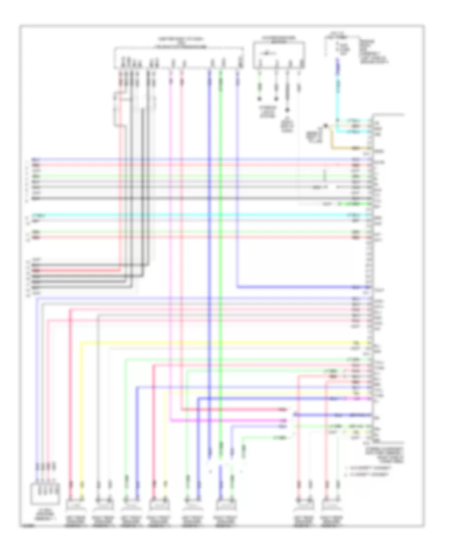
Radio Wiring Diagram, without Navigation with Separate Amplifier (3 of 3) for Toyota 4Runner SR5 2010
List of elements for Radio Wiring Diagram, without Navigation with Separate Amplifier (3 of 3) for Toyota 4Runner SR5 2010:
- (center right of dash) dcm (telematics transceiver)
- (or pnk)
- +b2
- Acc
- Engine room r/b assembly (left side of engine compt)
- Fl+
- Fl-
- Fr+
- Fr-
- Fuse amp 30a
- G1 (right end of dash)
- Gnd
- Gnd2
- Hot at all times
- Il+2
- Il-2
- Int+
- Int-
- Interior lights system
- Left front speaker assembly 1
- Left front speaker assembly 2
- Left rear speaker 1 assembly
- Left rear speaker assembly 2
- Mci+
- Mci-
- Mco+
- Mco-
- Mcvd
- Mute
- N11
- N12
- N13
- N14
- N2 (base of right "d" pillar)
- Nca
- Pnk
- R-l+
- R-l-
- R-r+
- R-r-
- Red
- Right front speaker assembly 1
- Right front speaker assembly 2
- Right rear speaker 1 assembly
- Right rear speaker assembly 2
- Rl+
- Rl-
- Rr+
- Rr-
- Sgnd
- Sld
- Spd
- Spi+
- Spi-
- Spo+
- Spo-
- Stereo component amplifier assembly (right side of cargo area)
- Sw+
- Sw-
- Tmut
- Twl+
- Twl-
- Twr+
- Twr-
- Tx+
- Tx-
- W/ box speaker assembly 1
- W/ safety connect
- W/o safety connect
- Wf-
- Wf1+
- Wf1-
- Wf2+
- Wf2-
- Woofer speaker switch