TRANSMISSION
2.5L
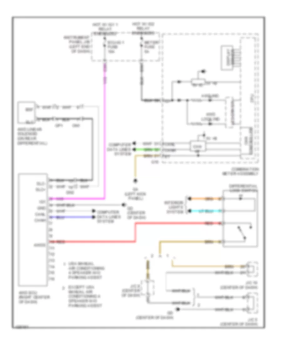
2.5L, 4WD Wiring Diagram for Toyota RAV4 XLE 2014
 https://portal-diagnostov.com/license.html
Automotive Electricians Portal FZCO
Automotive Electricians Portal FZCO
https://portal-diagnostov.com/license.html
https://portal-diagnostov.com/license.html
Automotive Electricians Portal FZCO
Automotive Electricians Portal FZCO
List of elements for 2.5L, 4WD Wiring Diagram for Toyota RAV4 XLE 2014:
- 4wd ecu (right center of dash)
- 4wd linear solenoid (on rear differential)
- 4wd lock ind
- 4wds
- 5v +b
- 5v ic
- Air conditioning 4 speaker w/o parking assist
- Awd ind
- Bsf
- C28
- Can i/f
- Canh
- Canl
- Combination meter assembly
- Computer data lines system
- Controller can
- Cpu
- D36
- Differential lock switch
- Driver display
- Ecu-ig 1 fuse 10a
- Except usa manual air conditioning 4 speaker w/o parking assist
- G16
- Ga (left kick panel)
- Gd (center of dash)
- Gn2
- Gnd
- Hot w/ ig1 1 relay energized
- Hot w/ ig2 relay energized
- Ig+
- Ig1
- Instrument panel j/b (left end of dash)
- Interior lights system
- J/c 10 (center of dash)
- J/c 5 (center of dash)
- J/c 9 (center of dash)
- Led driver
- Meter fuse 5a
- On1
- Op1
- Red
- Slc
- Slc+
- Slc-
- Usa manual
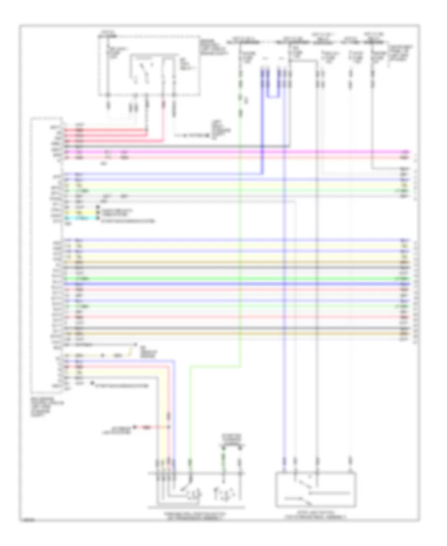
2.5L, A/T Wiring Diagram (1 of 2) for Toyota RAV4 XLE 2014
 https://portal-diagnostov.com/license.html
Automotive Electricians Portal FZCO
Automotive Electricians Portal FZCO
https://portal-diagnostov.com/license.html
https://portal-diagnostov.com/license.html
Automotive Electricians Portal FZCO
Automotive Electricians Portal FZCOList of elements for 2.5L, A/T Wiring Diagram (1 of 2) for Toyota RAV4 XLE 2014:
- (left front of engine compt) aa
- +b2
- A62
- Ag1
- B18
- B22
- B31
- B34
- B35
- B39
- B43
- B51
- B77
- Ba1
- Batt
- Bd (rear of engine)
- C27
- Canh
- Canl
- Computer data lines system
- D36
- Ecm (engine control module) (left side of engine compt)
- Ecu-ig 1 fuse 10a
- Efi main 1 fuse 20a
- Efi main relay 1
- Engine room r/b 1 (left side of engine compt)
- Eo4
- Etho
- Exterior lights system
- Gauge fuse 7.5a
- Hot at all times
- Hot w/ ig1 1 relay energized
- Hot w/ ig1 2 relay energized
- Hot w/ ig2 relay energized
- Ign fuse 7.5a
- Igsw
- Instrument panel j/b (left end of dash)
- Meter fuse 5a
- Mrel
- Ncb
- Nco
- Nsw
- Ntb
- Nto
- Park/neutral position switch (on transmission assembly)
- Pnk
- Pwms
- Red
- Sftd
- Sftu
- Sl1+
- Sl1-
- Sl2+
- Sl2-
- Sl3+
- Sl3-
- Sl4+
- Sl4-
- Slt+
- Slt-
- Slu+
- Slu-
- Spd
- St1-
- Sta
- Starting/ charging system
- Starting/charging system
- Stop fuse 7.5a
- Stop light switch (top of brake pedal assembly)
- Stp
- Tho1
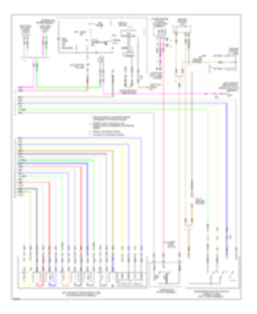
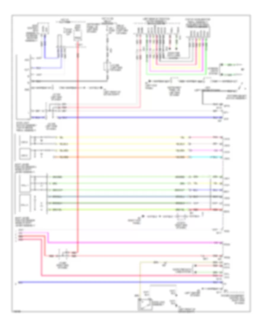
2.5L, A/T Wiring Diagram (2 of 2) for Toyota RAV4 XLE 2014
 https://portal-diagnostov.com/license.html
Automotive Electricians Portal FZCO
Automotive Electricians Portal FZCO
https://portal-diagnostov.com/license.html
https://portal-diagnostov.com/license.html
Automotive Electricians Portal FZCO
Automotive Electricians Portal FZCOList of elements for 2.5L, A/T Wiring Diagram (2 of 2) for Toyota RAV4 XLE 2014:
- (center of dash) j/c 5
- (center of dash) j/c 9
- (left kick panel) ga
- (left rear of engine compt) brake actuator assembly
- (left side of dash) j/c 1
- (lower center of dash) a/c amplifier assembly
- (right end of dash) j/c 13
- 5v +b
- 5v ic
- A/t oil temperature ind
- Ag1
- Ag4
- Automatic air conditioning
- Can controller
- Can i/f
- Canh
- Canl
- Chk
- Combination meter assembly
- Combination switch assembly
- Computer data lines system
- Cpu
- Display driver
- Eco mode ind (if equipped)
- Ecos
- Ect solenoid (transmission wire) (on transmission assembly)
- Ecu
- Except usa 4wd manual air conditioning 4 speaker w/o parking assist
- G16
- G80
- G81
- Gd (center of dash)
- Hall ic
- I/f
- Ig+
- J/c 10 (center of dash)
- Led driver
- Malfunction ind lamp
- Manual air conditioning
- Mode sw eco
- Msw1
- Msw2
- Ncb
- Nco
- Ntb
- Nto
- Oil
- Red
- Sftd
- Sftu
- Sl1+
- Sl1-
- Sl2+
- Sl2-
- Sl3+
- Sl3-
- Sl4+
- Sl4-
- Slt+
- Slt-
- Slu+
- Slu-
- Sp1
- Sport ind
- Sw sport
- Transmission control switch (base of floor shift lever assembly)
- Usa 4wd manual air conditioning 4 speaker w/o parking assist
- W/ eco mode switch
EV
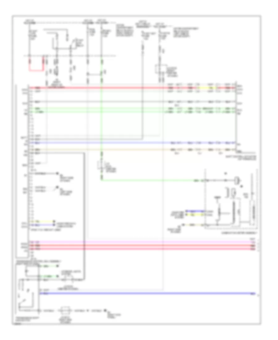
EV, Transmission Wiring Diagram (1 of 2) for Toyota RAV4 XLE 2014
 https://portal-diagnostov.com/license.html
Automotive Electricians Portal FZCO
Automotive Electricians Portal FZCO
https://portal-diagnostov.com/license.html
https://portal-diagnostov.com/license.html
Automotive Electricians Portal FZCO
Automotive Electricians Portal FZCOList of elements for EV, Transmission Wiring Diagram (1 of 2) for Toyota RAV4 XLE 2014:
- (pins 17-21 are not used)
- 5v ic
- 5v+b
- A3 (right front of motor compt)
- Ae1
- Ae7
- Ae8
- Batt
- Bma
- Buzzer
- Ca1h
- Ca1l
- Can controller
- Can i/f
- Canh
- Canl
- Combination meter assembly
- Computer data lines system
- Cpu
- Ch1
- E01
- E02
- E114
- E115
- E2 (left side of dash)
- E4 (right kick panel)
- E5 (right side of dash)
- Eco ind
- Ecu-b 2 fuse 7.5a
- El3
- El4
- Hot at all times
- Hot w/ igct 3 relay energized
- I/f
- Ind
- Interior lights system
- J/c e130 (right center of dash)
- J/c e131 (right end of dash)
- J/c e133 (center of dash)
- Led driver
- Lin
- Motor compartment relay block (left side of motor compt)
- Motor compartment relay block 2 (right side of motor compt)
- Mua
- Mva
- Mwa
- P cnt igct fuse 7.5a
- P cnt mtr fuse 30a
- P cnt mtr relay
- P cnt-b fuse 7.5a
- Pcon
- Pm-b fuse 7.5a
- Pnk
- Ppos
- Re2
- Red
- Rvc
- Shift control actuator (on transaxle)
- Transmission control ecu assembly (right end of dash)
- Transmission shift main switch
- Hl1
EV, Transmission Wiring Diagram (2 of 2) for Toyota RAV4 XLE 2014
 https://portal-diagnostov.com/license.html
Automotive Electricians Portal FZCO
Automotive Electricians Portal FZCO
https://portal-diagnostov.com/license.html
https://portal-diagnostov.com/license.html
Automotive Electricians Portal FZCO
Automotive Electricians Portal FZCOList of elements for EV, Transmission Wiring Diagram (2 of 2) for Toyota RAV4 XLE 2014:
- (left rear of traction motor assembly) drive inverter
- (top of accelerator pedal assembly) accelerator pedal position sensor
- A1 (left front of motor compt)
- A30
- A57
- Acc
- Acg2
- Acgd
- Acp2
- Acpwr
- Act1
- Act2
- Ae1
- Ae11
- Ae4
- Am22
- B12
- B18
- B21
- B43
- Bknc
- Bkno
- Ca1h
- Ca1l
- Computer data lines system
- D14
- Da1
- Da2
- E01
- E1 (left kick panel)
- E117
- E118
- E17
- E28
- E2x1
- E2x2
- E3 (left center of dash)
- E4 (right kick panel)
- Epa
- Epa2
- Ek1
- Gnd
- Hall 1
- Hall 2
- Hood lock assembly
- Hot at all times
- Hot w/ ig2 relay energized
- Ig2 1 fuse 5a
- Instrument panel j/b (left end of dash)
- Interior lights system
- J/b 5 (left center of dash)
- J/c a35 (left side of dash)
- J/c a38 (left end of dash)
- J/c a66 (left end of dash)
- J/c e131 (right end of dash)
- J/c e67 (right end of dash)
- Lin 2
- Main body ecu
- Mir ic
- Out
- Pattern select switch assembly
- Pcon
- Pnk
- Power management control ecu (right side of dash)
- Ppos
- Pros
- Red
- Relay block 6 (left end of dash)
- Sftd
- Sftu
- Shift lever position sensor (base of shift lever assembly)
- Shift lever position sensor 2 (base of shift lever assembly)
- Skid control ecu assembly (on brake booster assembly)
- St1-
- Stop fuse 10a
- Stop light switch assembly (top of brake pedal assembly)
- Stp
- Stpo
- Tsch
- Tscl
- Vcp2
- Vcpa
- Vcx1
- Vcx2
- Vcx3
- Vcx4
- Vpa
- Vpa2
- Vsx1
- Vsx2
- Vsx3
- Vsx4

 Čeština
 Dansk
Dansk Deutsch
 Ελληνικά
 English
 English
 Español
 Suomi
Suomi Français
 Français
 עברית
עברית Hrvatski
 Magyar
 Italiano
 日本語
日本語 한국어
한국어 Nederlands
 Polski
 Português
 Português
 Română
 Русский
 Slovenčina
 Slovenščina
 Svenska
 Türkçe
