WARNING SYSTEMS
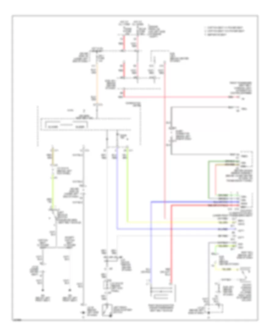
Key Reminder & Seat Belt Warning Wiring Diagram, Access/Standard Cab for Toyota Tundra SR5 2006
 https://portal-diagnostov.com/license.html
Automotive Electricians Portal FZCO
Automotive Electricians Portal FZCO
https://portal-diagnostov.com/license.html
https://portal-diagnostov.com/license.html
Automotive Electricians Portal FZCO
Automotive Electricians Portal FZCO
List of elements for Key Reminder & Seat Belt Warning Wiring Diagram, Access/Standard Cab for Toyota Tundra SR5 2006:
- (access cab: under front
- (bench seat & separate seat:
- (or pnk)
- Acc
- Acc fuse 15a
- Bench seat
- Bgnd
- Blinker
- Bsw
- Buzzer
- C11
- C12
- Captain seat
- Captain seat w/ power seat
- Captain seat w/o power seat
- Center air bag sensor assembly (behind lower center of dash, on transmission tunnel)
- Column)
- Combination meter
- Compt)
- Diode (door courtesy) (behind upper left side of dash, near instrument cluster)
- Dome fuse 10a
- Door ind
- Driver side j/b (behind lower left side
- Driver's seat belt ind
- Engine room r/b (on left side of engine
- Except captain seat w/ power seat
- F10
- Fsp+
- Fsp-
- Fsr+
- Fsr-
- G10
- Hot at all times
- Hot in on or acc
- Hot in on or start
- I25
- Ie (behind left kick panel)
- Ign fuse 5a
- Ih (behind right kick panel)
- In passenger's seat bottom)
- Integration control & panel
- J/c 13 (behind right kick panel)
- J/c 23 (behind left end of dash)
- J/c 3 (behind left kick panel)
- J/c 4 (behind left kick panel)
- J/c 66 & 67 (behind right kick panel)
- J/c 7 (behind upper left side of dash, near instru- ment cluster)
- J/c 7 (behind upper left side of dash, near instrument cluster)
- J/c 83 (under driver seat)
- J/c 9 (behind upper left side of dash, near instrument cluster)
- J66 b
- J67 d
- Left buckle switch (inside driver's seat belt buckle)
- Left front door courtesy switch
- O10
- O16
- Occupant classification ecu
- Of dash)
- P-ab
- Paon
- Passenger's seat)
- Pbew
- Pbkl
- Red
- Right buckle switch (access cab: inside front passenger's seat belt buckle) (standard cab: inside passenger's seat belt buckle)
- Separate seat
- Separate seat &
- Unlock warning switch (in upper right side of steering
- W/ immobilizer
- W/o immobilizer
Key Reminder & Seat Belt Warning Wiring Diagram, Double Cab for Toyota Tundra SR5 2006
 https://portal-diagnostov.com/license.html
Automotive Electricians Portal FZCO
Automotive Electricians Portal FZCO
https://portal-diagnostov.com/license.html
https://portal-diagnostov.com/license.html
Automotive Electricians Portal FZCO
Automotive Electricians Portal FZCO
List of elements for Key Reminder & Seat Belt Warning Wiring Diagram, Double Cab for Toyota Tundra SR5 2006:
- A j39
- A10
- A19
- Acty
- B10
- B11
- Becu
- Bgnd
- Blinker
- Body ecu (behind left side of dash)
- Bq (below left front seat)
- Bsw
- Buzzer
- C11
- C12
- Captain seat w/ power seat
- Captain seat w/o power seat
- Center air bag sensor assembly (behind lower center of dash, on transmission tunnel)
- Combination meter
- D10
- Dcty
- Dome fuse 10a
- Door ind
- Driver side j/b (under left end of dash)
- Driver's seat belt ind
- Ecu-b fuse 7.5a
- Engine room j/b (on left side of engine compt)
- Except captain seat w/ power seat
- F j42
- Front passenger seat belt warning light (integration control & panel)
- Fsr+
- Fsr-
- Gnd
- H11
- Hot at all times
- Hot in on or start
- I25
- Ign 1 fuse 10a
- J/c 38 & 39 (behind left kick
- J/c 42 & 43 (behind left kick panel)
- J/c 45 (behind left side of dash)
- J/c 49 & 50 (behind center of dash)
- J/c 82 (under driver seat)
- J38 h
- J49
- J50
- Ksw
- Ksw2
- L j43
- Left buckle switch (inside driver's seat belt buckle)
- Left front door courtesy switch
- O10
- O16
- Occupant classification ecu (under front passenger's seat)
- Panel)
- Pbew
- Pbkl
- Red
- Right buckle switch (inside passenger's seat belt buckle)
- S13
- S14
- Separate seat
- Short connector (behind left side of dash)
- Sub j/b 3 (behind center of dash)
- Sub j/b 4 (behind center of dash)
- Unlock warning switch (in upper right side of steering column)
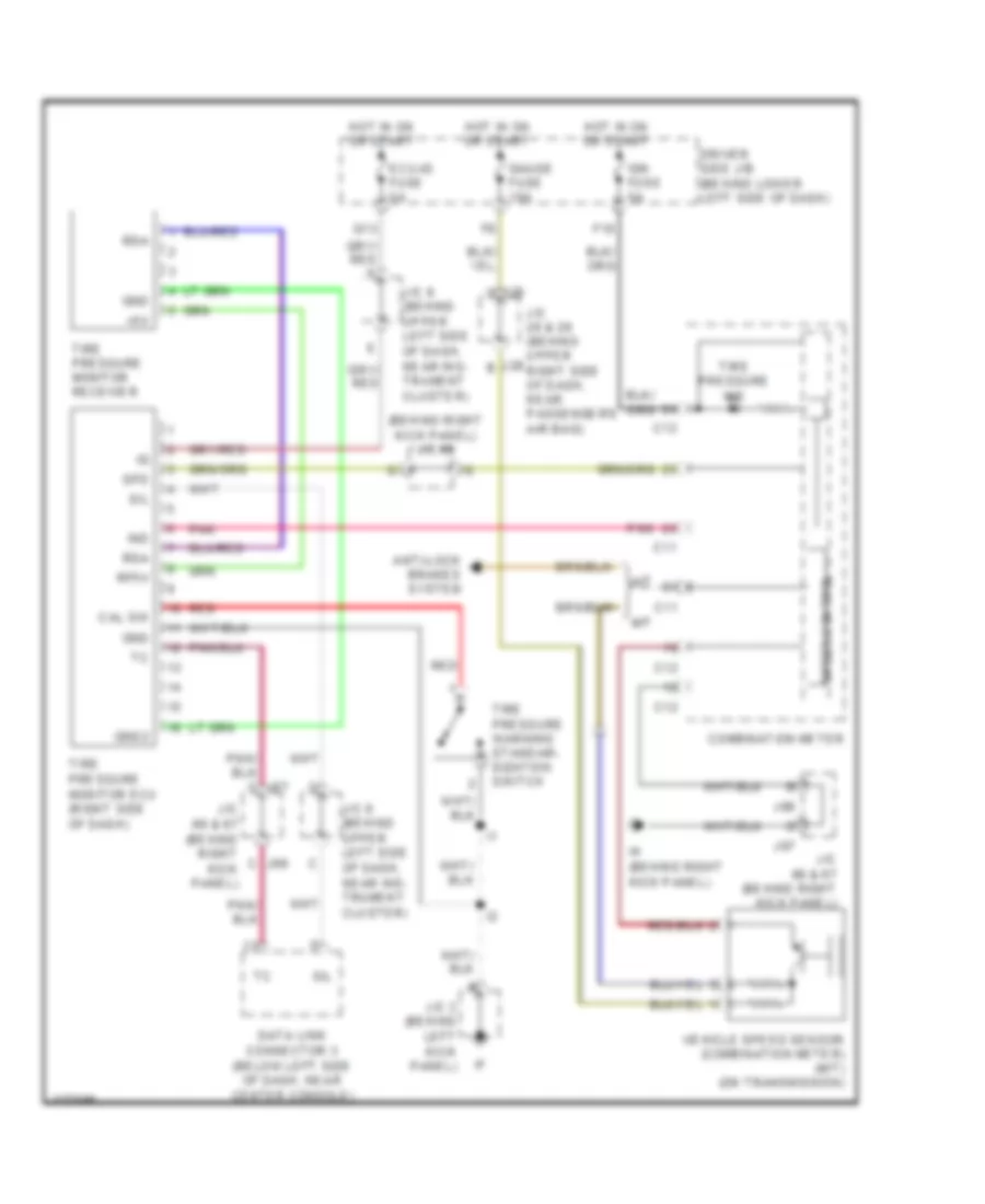
Tire Pressure Monitoring Wiring Diagram, Access/Standard Cab for Toyota Tundra SR5 2006
 https://portal-diagnostov.com/license.html
Automotive Electricians Portal FZCO
Automotive Electricians Portal FZCO
https://portal-diagnostov.com/license.html
https://portal-diagnostov.com/license.html
Automotive Electricians Portal FZCO
Automotive Electricians Portal FZCO
List of elements for Tire Pressure Monitoring Wiring Diagram, Access/Standard Cab for Toyota Tundra SR5 2006:
- (behind right kick panel) j/c 66
- +5v
- A/t
- Anti-lock brakes system
- C j66
- C11
- C12
- Cal sw
- Combination meter
- Data link connector 3 (below left side of dash, near center console)
- Driver side j/b (behind lower left side of dash)
- Ecu-ig fuse 5a
- F10
- G13
- Gauge fuse 10a
- Gnd
- Gnd2
- Hot in on or start
- Ign fuse 5a
- Ih (behind right kick panel)
- Ind
- J/c 28 & 29 (behind upper right side of dash, near passenger's air bag)
- J/c 3 (behind left kick panel)
- J/c 66 & 67 (behind right kick panel)
- J/c 8 (behind upper left side of dash, near ins- trument cluster)
- J/c 9 (behind upper left side of dash, near ins- trument cluster)
- J28 b
- J29 d
- J66
- J67
- M/t
- Pnk
- Rda
- Red
- Rf5v
- Sil
- Spd
- Speed control
- Tire pressure ind
- Tire pressure monitor ecu (right side of dash)
- Tire pressure monitor receiver
- Tire pressure warning standar- dization switch
- Vehicle speed sensor (combination meter) (m/t) (on transmission)
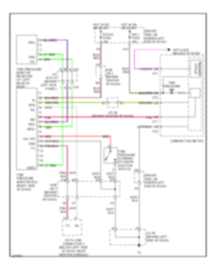
Tire Pressure Monitoring Wiring Diagram, Double Cab for Toyota Tundra SR5 2006
 https://portal-diagnostov.com/license.html
Automotive Electricians Portal FZCO
Automotive Electricians Portal FZCO
https://portal-diagnostov.com/license.html
https://portal-diagnostov.com/license.html
Automotive Electricians Portal FZCO
Automotive Electricians Portal FZCO
List of elements for Tire Pressure Monitoring Wiring Diagram, Double Cab for Toyota Tundra SR5 2006:
- +5v
- A j43
- Anti-lock brakes system
- C11
- C12
- Cal sw
- Combination meter
- Data link connector 3 (below left side of dash, near center console)
- Driver side j/b (under left end of dash)
- Ecu-ig fuse 10a
- Gnd
- Gnd2
- H11
- Hot in on or start
- Ign 1 fuse 10a
- Ind
- J/c 42 & 43 (behind left kick panel)
- J/c 45 (behind left side of dash)
- J/c 49 (behind center of dash)
- J42 g
- Pnk
- Rda
- Red
- Rf5v
- Sil
- Spd
- Speed control
- Sub j/b 3 (behind center of dash)
- Tire pressure ind
- Tire pressure monitor ecu (right side of dash)
- Tire pressure monitor receiver (at left rear of roof)
- Tire pressure warning standar- dization switch

 Deutsch
 English
 English
 Español
 Français
 Nederlands
 Русский


