AIR CONDITIONING
3.8L VIN 2
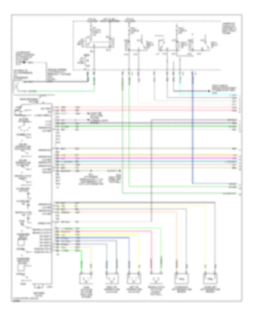
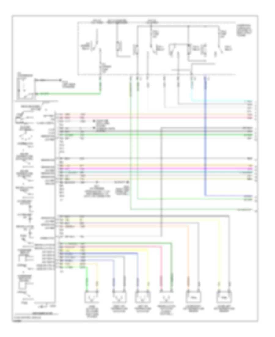
3.8L VIN 2, Automatic A/C Wiring Diagram (1 of 2) for Pontiac Grand Prix GT 2006
 https://portal-diagnostov.com/license.html
Automotive Electricians Portal FZCO
Automotive Electricians Portal FZCO
https://portal-diagnostov.com/license.html
https://portal-diagnostov.com/license.html
Automotive Electricians Portal FZCO
Automotive Electricians Portal FZCO
List of elements for 3.8L VIN 2, Automatic A/C Wiring Diagram (1 of 2) for Pontiac Grand Prix GT 2006:
- (engine harness, 10 cm from g113 breakout, towards pcm) (sulev) s104
- (lower right front of engine, on transaxle stud, near starter) g113
- (on front of a/c compressor) a/c compressor clutch
- (right side of engine compartment, at base of battery) g100
- A/c clu diode
- A/c clutch fuse 13 10a
- A/c comp relay
- A/c request ind
- A/c request switch
- A10
- A11
- A12
- A18
- A19
- Air temp a
- Air temp b
- Auto
- B10
- B11
- B12
- Battery
- Blower motor sw
- C18
- C19
- Class 2 serial
- Computer data lines system interior lights system
- Defogger on ind
- Display
- Driver temperature down control
- Driver temperature up control
- E10
- Fan 1 fuse 29 30a
- Fan 1 relay
- Fan 2 fuse 32 30a
- Fan 2 relay
- Fan 3 relay
- G202 (right side upper left footwell)
- Ground
- High
- Hot at all times
- Hot w/ ign 1 relay energized
- Hvac control module
- Ign
- Illum
- Ind
- K14
- K15
- K18
- K19
- L14
- Left air temperature actuator
- Logic
- Low
- Low ref
- Lower left air temperature sensor
- Lower right air temperature sensor
- M14
- M15
- M18
- M19
- Mode actuator (on lower right side of dash)
- Mode dr ctrl a
- Mode dr ctrl b
- Mode switch
- Off
- Pass
- Passenger temp down control
- Passenger temp up control
- Pnk
- Rear defogger switch
- Recirculation
- Recirculation a
- Recirculation actuator (in right footwell)
- Recirculation b
- Recirculation switch
- Right air temperature actuator
- S211 (i/p harness, approximately 11 cm from breakout to data link connector)
- Sensor sig
- Speed ctrl
- Tan
- Underhood fuse block (mounted to right strut tower)
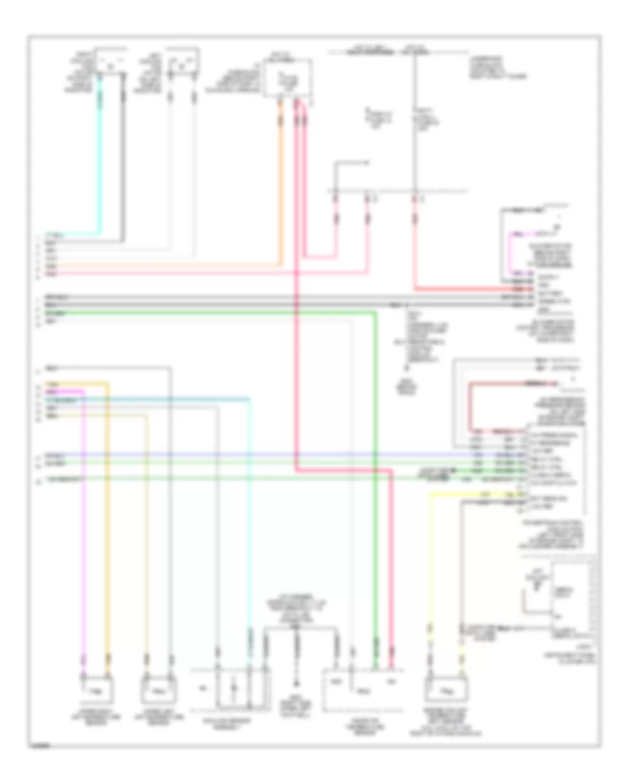
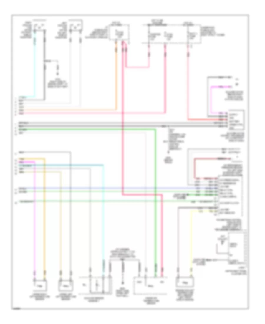
3.8L VIN 2, Automatic A/C Wiring Diagram (2 of 2) for Pontiac Grand Prix GT 2006
 https://portal-diagnostov.com/license.html
Automotive Electricians Portal FZCO
Automotive Electricians Portal FZCO
https://portal-diagnostov.com/license.html
https://portal-diagnostov.com/license.html
Automotive Electricians Portal FZCO
Automotive Electricians Portal FZCOList of elements for 3.8L VIN 2, Automatic A/C Wiring Diagram (2 of 2) for Pontiac Grand Prix GT 2006:
- (i/p harness, approximately 11 cm from breakout to data link connector) s211
- 5v reference
- A/c comp clutch
- A/c press signal
- A/c refrigerant pressure sensor (on left side of engine compt, on accumulator)
- Batt main 4 fuse 30 30a
- Battery
- Blower motor (behind right side of dash, in hvac module)
- Blower motor control processor (on lower right side of dash)
- Class 2 serial
- Class 2 serial data
- Computer data lines system
- D11
- Display fuse 18 10a
- Ect sens sig
- Engine coolant temperature (ect) sensor (3.8l (vin 2): on top right of intake manifold)
- G200 (behind radio)
- G202 (right side upper left footwell)
- Gnd
- Hot at all times
- Hot coolant ind
- Hot w/ ign 1 relay energized
- Hvac fuse 10a
- I/p fuse block (behind right side of dash, in glove box opening)
- Ign
- Inside air temperature sensor
- Instrument panel cluster (ipc)
- Left cooling fan motor (on left side of radiator)
- Logic
- Low ref
- Pnk
- Powertrain control module (pcm) (left front side of engine compt, in air cleaner assembly)
- Red
- Relay ctrl
- Right cooling fan motor (on right b
- S213 (i/p harness, 4 cm from blower motor resistors & control module breakout)
- Serial data
- Speed ctrl
- Sunload sensor assembly
- Tan
- Underhood fuse block (mounted to right strut tower)
- Upper left air temperature sensor
- Upper right air temperature sensor
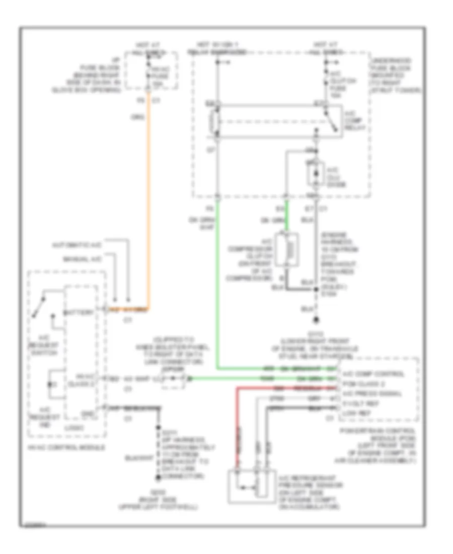
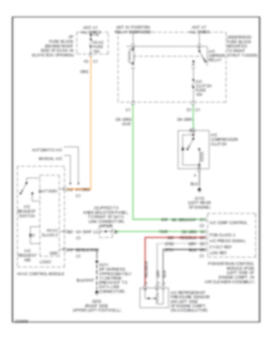
3.8L VIN 2, Compressor Wiring Diagram for Pontiac Grand Prix GT 2006
 https://portal-diagnostov.com/license.html
Automotive Electricians Portal FZCO
Automotive Electricians Portal FZCO
https://portal-diagnostov.com/license.html
https://portal-diagnostov.com/license.html
Automotive Electricians Portal FZCO
Automotive Electricians Portal FZCOList of elements for 3.8L VIN 2, Compressor Wiring Diagram for Pontiac Grand Prix GT 2006:
- (clipped to knee-bolster panel, to right of data link connector) sp205
- (engine harness, 10 cm from g113 breakout, towards pcm) (sulev) s104
- 5 volt ref
- A/c clu diode
- A/c clutch fuse 10a
- A/c comp control
- A/c comp relay
- A/c compressor clutch (on front of a/c compressor) b
- A/c press signal
- A/c refrigerant pressure sensor (on left side of engine compt, on accumulator)
- A/c request ind
- A/c request switch
- Automatic a/c
- Battery
- G113 (lower right front of engine, on transaxle stud, near starter)
- G202 (right side upper left footwell)
- Gnd
- Hot at all times
- Hot w/ ign 1 relay energized
- Hvac class 2
- Hvac control module
- Hvac fuse 10a
- I/p fuse block (behind right side of dash, in glove box opening)
- Logic
- Low ref
- Manual a/c
- Pcm class 2
- Powertrain control module (pcm) (left front side of engine compt, in air cleaner assembly)
- S211 (i/p harness, approximately 11 cm from breakout to data link connector)
- Underhood fuse block (mounted to right strut tower)
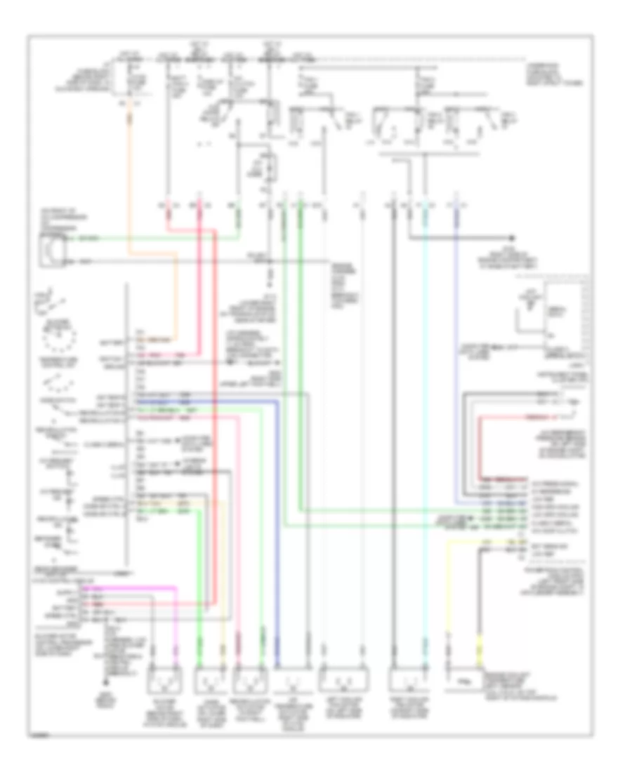
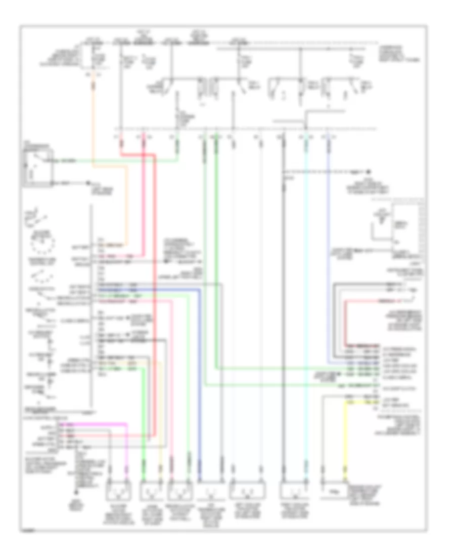
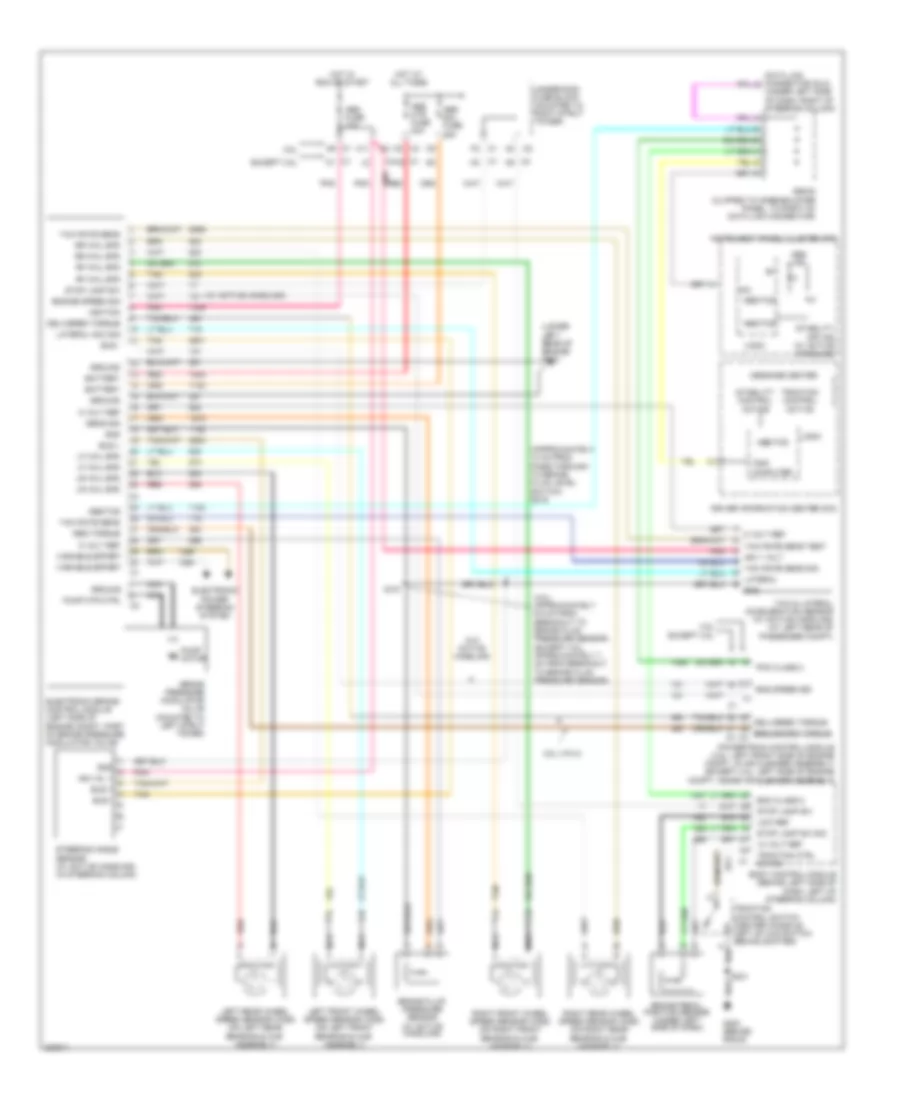
3.8L VIN 2, Manual A/C Wiring Diagram for Pontiac Grand Prix GT 2006
 https://portal-diagnostov.com/license.html
Automotive Electricians Portal FZCO
Automotive Electricians Portal FZCO
https://portal-diagnostov.com/license.html
https://portal-diagnostov.com/license.html
Automotive Electricians Portal FZCO
Automotive Electricians Portal FZCOList of elements for 3.8L VIN 2, Manual A/C Wiring Diagram for Pontiac Grand Prix GT 2006:
- (engine harness, 10 cm from g113 breakout, towards pcm)
- (i/p harness, approximately 11 cm from breakout to data link connector) s211
- (on front of a/c compressor) a/c compressor clutch
- (sulev) s104
- 5v reference
- A/c clu diode
- A/c clutch fuse 10a
- A/c comp clutch
- A/c comp relay
- A/c press signal
- A/c refrigerant pressure sensor (on left side of engine compt, on accumulator)
- A/c request ind
- A/c request switch
- A10
- A11
- A12
- A18
- A19
- Air temp a
- Air temp b
- Air temperature actuator (right side of hvac module)
- B10
- B11
- B12
- Batt main 4 fuse 30a
- Battery
- Blower motor (behind right side of dash, in hvac module)
- Blower motor control processor (on lower right side of dash)
- Blower motor sw
- C18
- C19
- Class 2 serial
- Class 2 serial data
- Computer data lines system
- Defogger on ind
- Display fuse 10a
- E10
- Ect sens sig
- Engine coolant temperature (ect) sensor (3.8l (vin 2): on top right of intake manifold)
- Fan 1 fuse 30a
- Fan 1 relay
- Fan 2 fuse 30a
- Fan 2 relay
- Fan 3 relay
- G100 (right side of engine compartment, at base of battery)
- G113 (lower right front of engine, on transaxle stud, near starter)
- G200 (behind radio)
- G202 (right side upper left footwell)
- Gnd
- Ground
- High
- High spd cooling
- Hot at all times
- Hot coolant ind
- Hot w/ ign 1 relay energized
- Hvac control module
- Hvac fuse 10a
- I/p fuse block (behind right side of dash, in glove box opening)
- Ignition 1
- Illum
- Ind
- Instrument panel cluster (ipc)
- Interior lights system
- K14
- K15
- K18
- K19
- L14
- Left cooling fan motor (on left side of radiator)
- Logic
- Low
- Low ref
- Low spd cooling
- M14
- M15
- M18
- M19
- Mode actuator (on lower right side of dash)
- Mode dr ctrl a
- Mode dr ctrl b
- Mode switch
- Off
- Pnk
- Powertrain control module (pcm) (left front side of engine compt, in air cleaner assembly)
- Rear defogger switch
- Recirculation
- Recirculation a
- Recirculation actuator (in right footwell)
- Recirculation b
- Recirculation switch
- Red
- Right cooling fan motor (on right side of radiator)
- S213 (i/p harness, 4 cm from blower motor resistors & control module breakout)
- Serial data
- Speed ctrl
- Tan
- Temperature control sw
- Underhood fuse block (mounted to right strut tower)
3.8L VIN 4
3.8L VIN 4, Automatic A/C Wiring Diagram (1 of 2) for Pontiac Grand Prix GT 2006
 https://portal-diagnostov.com/license.html
Automotive Electricians Portal FZCO
Automotive Electricians Portal FZCO
https://portal-diagnostov.com/license.html
https://portal-diagnostov.com/license.html
Automotive Electricians Portal FZCO
Automotive Electricians Portal FZCOList of elements for 3.8L VIN 4, Automatic A/C Wiring Diagram (1 of 2) for Pontiac Grand Prix GT 2006:
- (engine harness, 10 cm from g113 breakout, towards pcm) (sulev) s104
- (lower right front of engine, on transaxle stud, near starter) g113
- (on front of a/c compressor) a/c compressor clutch
- (right side of engine compartment, at base of battery) g100
- A/c clu diode
- A/c clutch fuse 13 10a
- A/c comp relay
- A/c request ind
- A/c request switch
- A10
- A11
- A12
- A18
- A19
- Air temp a
- Air temp b
- Auto
- B10
- B11
- B12
- Battery
- Blower motor sw
- C18
- C19
- Class 2 serial
- Computer data lines system interior lights system
- Defogger on ind
- Display
- Driver temperature down control
- Driver temperature up control
- E10
- Fan 1 fuse 29 30a
- Fan 1 relay
- Fan 2 fuse 32 30a
- Fan 2 relay
- Fan 3 relay
- G202 (right side upper left footwell)
- Ground
- High
- Hot at all times
- Hot w/ ign 1 relay energized
- Hvac control module
- Ign
- Illum
- Ind
- K14
- K15
- K18
- K19
- L14
- Left air temperature actuator
- Logic
- Low
- Low ref
- Lower left air temperature sensor
- Lower right air temperature sensor
- M14
- M15
- M18
- M19
- Mode actuator (on lower right side of dash)
- Mode dr ctrl a
- Mode dr ctrl b
- Mode switch
- Off
- Pass
- Passenger temp down control
- Passenger temp up control
- Pnk
- Rear defogger switch
- Recirculation
- Recirculation a
- Recirculation actuator (in right footwell)
- Recirculation b
- Recirculation switch
- Right air temperature actuator
- S211 (i/p harness, approximately 11 cm from breakout to data link connector)
- Sensor sig
- Speed ctrl
- Tan
- Underhood fuse block (mounted to right strut tower)
3.8L VIN 4, Automatic A/C Wiring Diagram (2 of 2) for Pontiac Grand Prix GT 2006
 https://portal-diagnostov.com/license.html
Automotive Electricians Portal FZCO
Automotive Electricians Portal FZCO
https://portal-diagnostov.com/license.html
https://portal-diagnostov.com/license.html
Automotive Electricians Portal FZCO
Automotive Electricians Portal FZCOList of elements for 3.8L VIN 4, Automatic A/C Wiring Diagram (2 of 2) for Pontiac Grand Prix GT 2006:
- (i/p harness, approximately 11 cm from breakout to data link connector) s211
- 5v reference
- A/c comp clutch
- A/c press signal
- A/c refrigerant pressure sensor (on left side of engine compt, on accumulator)
- Batt main 4 fuse 30 30a
- Battery
- Blower motor (behind right side of dash, in hvac module)
- Blower motor control processor (on lower right side of dash)
- Class 2 serial
- Class 2 serial data
- Computer data lines system
- D11
- Display fuse 18 10a
- Ect sens sig
- Engine coolant temperature (ect) sensor (3.8l (vin 2): on top right of intake manifold)
- G200 (behind radio)
- G202 (right side upper left footwell)
- Gnd
- Hot at all times
- Hot coolant ind
- Hot w/ ign 1 relay energized
- Hvac fuse 10a
- I/p fuse block (behind right side of dash, in glove box opening)
- Ign
- Inside air temperature sensor
- Instrument panel cluster (ipc)
- Left cooling fan motor (on left side of radiator)
- Logic
- Low ref
- Pnk
- Powertrain control module (pcm) (left front side of engine compt, in air cleaner assembly)
- Red
- Relay ctrl
- Right cooling fan motor (on right b
- S213 (i/p harness, 4 cm from blower motor resistors & control module breakout)
- Serial data
- Speed ctrl
- Sunload sensor assembly
- Tan
- Underhood fuse block (mounted to right strut tower)
- Upper left air temperature sensor
- Upper right air temperature sensor
3.8L VIN 4, Compressor Wiring Diagram for Pontiac Grand Prix GT 2006
 https://portal-diagnostov.com/license.html
Automotive Electricians Portal FZCO
Automotive Electricians Portal FZCO
https://portal-diagnostov.com/license.html
https://portal-diagnostov.com/license.html
Automotive Electricians Portal FZCO
Automotive Electricians Portal FZCOList of elements for 3.8L VIN 4, Compressor Wiring Diagram for Pontiac Grand Prix GT 2006:
- (clipped to knee-bolster panel, to right of data link connector) sp205
- (engine harness, 10 cm from g113 breakout, towards pcm) (sulev) s104
- 5 volt ref
- A/c clu diode
- A/c clutch fuse 10a
- A/c comp control
- A/c comp relay
- A/c compressor clutch (on front of a/c compressor) b
- A/c press signal
- A/c refrigerant pressure sensor (on left side of engine compt, on accumulator)
- A/c request ind
- A/c request switch
- Automatic a/c
- Battery
- G113 (lower right front of engine, on transaxle stud, near starter)
- G202 (right side upper left footwell)
- Gnd
- Hot at all times
- Hot w/ ign 1 relay energized
- Hvac class 2
- Hvac control module
- Hvac fuse 10a
- I/p fuse block (behind right side of dash, in glove box opening)
- Logic
- Low ref
- Manual a/c
- Pcm class 2
- Powertrain control module (pcm) (left front side of engine compt, in air cleaner assembly)
- S211 (i/p harness, approximately 11 cm from breakout to data link connector)
- Underhood fuse block (mounted to right strut tower)
3.8L VIN 4, Manual A/C Wiring Diagram for Pontiac Grand Prix GT 2006
 https://portal-diagnostov.com/license.html
Automotive Electricians Portal FZCO
Automotive Electricians Portal FZCO
https://portal-diagnostov.com/license.html
https://portal-diagnostov.com/license.html
Automotive Electricians Portal FZCO
Automotive Electricians Portal FZCOList of elements for 3.8L VIN 4, Manual A/C Wiring Diagram for Pontiac Grand Prix GT 2006:
- (engine harness, 10 cm from g113 breakout, towards pcm)
- (i/p harness, approximately 11 cm from breakout to data link connector) s211
- (on front of a/c compressor) a/c compressor clutch
- (sulev) s104
- 5v reference
- A/c clu diode
- A/c clutch fuse 10a
- A/c comp clutch
- A/c comp relay
- A/c press signal
- A/c refrigerant pressure sensor (on left side of engine compt, on accumulator)
- A/c request ind
- A/c request switch
- A10
- A11
- A12
- A18
- A19
- Air temp a
- Air temp b
- Air temperature actuator (right side of hvac module)
- B10
- B11
- B12
- Batt main 4 fuse 30a
- Battery
- Blower motor (behind right side of dash, in hvac module)
- Blower motor control processor (on lower right side of dash)
- Blower motor sw
- C18
- C19
- Class 2 serial
- Class 2 serial data
- Computer data lines system
- Defogger on ind
- Display fuse 10a
- E10
- Ect sens sig
- Engine coolant temperature (ect) sensor (3.8l (vin 2): on top right of intake manifold)
- Fan 1 fuse 30a
- Fan 1 relay
- Fan 2 fuse 30a
- Fan 2 relay
- Fan 3 relay
- G100 (right side of engine compartment, at base of battery)
- G113 (lower right front of engine, on transaxle stud, near starter)
- G200 (behind radio)
- G202 (right side upper left footwell)
- Gnd
- Ground
- High
- High spd cooling
- Hot at all times
- Hot coolant ind
- Hot w/ ign 1 relay energized
- Hvac control module
- Hvac fuse 10a
- I/p fuse block (behind right side of dash, in glove box opening)
- Ignition 1
- Illum
- Ind
- Instrument panel cluster (ipc)
- Interior lights system
- K14
- K15
- K18
- K19
- L14
- Left cooling fan motor (on left side of radiator)
- Logic
- Low
- Low ref
- Low spd cooling
- M14
- M15
- M18
- M19
- Mode actuator (on lower right side of dash)
- Mode dr ctrl a
- Mode dr ctrl b
- Mode switch
- Off
- Pnk
- Powertrain control module (pcm) (left front side of engine compt, in air cleaner assembly)
- Rear defogger switch
- Recirculation
- Recirculation a
- Recirculation actuator (in right footwell)
- Recirculation b
- Recirculation switch
- Red
- Right cooling fan motor (on right side of radiator)
- S213 (i/p harness, 4 cm from blower motor resistors & control module breakout)
- Serial data
- Speed ctrl
- Tan
- Temperature control sw
- Underhood fuse block (mounted to right strut tower)
5.3L VIN C
5.3L VIN C, Automatic A/C Wiring Diagram (1 of 2) for Pontiac Grand Prix GT 2006
 https://portal-diagnostov.com/license.html
Automotive Electricians Portal FZCO
Automotive Electricians Portal FZCO
https://portal-diagnostov.com/license.html
https://portal-diagnostov.com/license.html
Automotive Electricians Portal FZCO
Automotive Electricians Portal FZCOList of elements for 5.3L VIN C, Automatic A/C Wiring Diagram (1 of 2) for Pontiac Grand Prix GT 2006:
- A/c compressor clutch
- A/c cmprsr fuse 10a
- A/c cmprsr relay
- A/c request ind
- A/c request switch
- A10
- A11
- A12
- Air temp a
- Air temp b
- Auto
- B10
- B11
- B12
- Battery
- Blower motor sw
- Class 2 serial
- Computer data lines system interior lights system
- Defogger on ind
- Display
- Driver temperature down control
- Driver temperature up control
- Fan 1 fuse 30a
- Fan 1 relay
- Fan 2 fuse 30a
- Fan 2 relay
- Fan 3 relay
- G112 (left rear of engine)
- G202 (right side upper left footwell)
- Ground
- High
- Hot at all times
- Hot w/ pwr/trn relay energized
- Hvac control module
- Ign
- Illum
- Ind
- Left air temperature actuator
- Logic
- Low
- Low ref
- Lower left air temperature sensor
- Lower right air temperature sensor
- Mode actuator (on lower right side of dash)
- Mode dr ctrl a
- Mode dr ctrl b
- Mode switch
- Off
- Pass
- Passenger temp down control
- Passenger temp up control
- Pnk
- Rear defogger switch
- Recirculation
- Recirculation a
- Recirculation actuator (in right footwell)
- Recirculation b
- Recirculation switch
- Right air temperature actuator
- S211 (i/p harness, approximately 11 cm from breakout to data link connector)
- Sensor sig
- Speed ctrl
- Tan
- Underhood fuse block (mounted to right strut tower)
5.3L VIN C, Automatic A/C Wiring Diagram (2 of 2) for Pontiac Grand Prix GT 2006
 https://portal-diagnostov.com/license.html
Automotive Electricians Portal FZCO
Automotive Electricians Portal FZCO
https://portal-diagnostov.com/license.html
https://portal-diagnostov.com/license.html
Automotive Electricians Portal FZCO
Automotive Electricians Portal FZCOList of elements for 5.3L VIN C, Automatic A/C Wiring Diagram (2 of 2) for Pontiac Grand Prix GT 2006:
- (i/p harness, approximately 11 cm from breakout to data link connector) s211
- 5v reference
- A/c comp clutch
- A/c press signal
- A/c refrigerant pressure sensor (on left side of engine compt, on accumulator)
- Batt 4 fuse 30a
- Battery
- Blower motor (behind right side of dash, in hvac module)
- Blower motor control processor (on lower right side of dash)
- Class 2 serial
- Class 2 serial data
- Compass fuse 10a
- Computer data lines system
- D11
- Ect sens sig
- Engine coolant temperature (ect) sensor (left front side of engine)
- G100 (right side of engine compt, at base of battery)
- G200 (behind radio)
- G202 (right side upper left footwell)
- Gnd
- Hot at all times
- Hot coolant ind
- Hot w/ ign main pcb relay energized
- Hvac fuse 10a
- I/p fuse block (behind right side of dash, in glove box opening)
- Ign
- Inside air temperature sensor
- Instrument panel cluster (ipc)
- Left cooling fan motor (on left side of radiator)
- Logic
- Low ref
- Pnk
- Powertrain control module (pcm) (left side of engine compt, in air cleaner assembly)
- Red
- Relay ctrl
- Right cooling fan motor (on right b
- S123
- S213 (i/p harness, 4 cm from blower motor resistors & control module breakout)
- Serial data
- Speed ctrl
- Sunload sensor assembly
- Tan
- Underhood fuse block (mounted to right strut tower)
- Upper left air temperature sensor
- Upper right air temperature sensor
5.3L VIN C, Compressor Wiring Diagram for Pontiac Grand Prix GT 2006
 https://portal-diagnostov.com/license.html
Automotive Electricians Portal FZCO
Automotive Electricians Portal FZCO
https://portal-diagnostov.com/license.html
https://portal-diagnostov.com/license.html
Automotive Electricians Portal FZCO
Automotive Electricians Portal FZCOList of elements for 5.3L VIN C, Compressor Wiring Diagram for Pontiac Grand Prix GT 2006:
- (clipped to knee-bolster panel, to right of data link connector) sp205
- 5 volt ref
- A/c compressor clutch
- A/c clutch fuse 10a
- A/c cmprsr relay
- A/c comp control
- A/c press signal
- A/c refrigerant pressure sensor (on left side of engine compt, on accumulator)
- A/c request ind
- A/c request switch
- Automatic a/c
- Battery
- G112 (left rear of engine)
- G202 (right side upper left footwell)
- Gnd
- Hot at all times
- Hot w/ pwr/trn relay energized
- Hvac class 2
- Hvac control module
- Hvac fuse 10a
- I/p fuse block (behind right side of dash, in glove box opening)
- Logic
- Low ref
- Manual a/c
- Pcm class 2
- Powertrain control module (pcm) (left side of engine compt, in air cleaner assembly)
- S211 (i/p harness, approximately 11 cm from breakout to data link connector)
- Underhood fuse block (mounted to right strut tower)
5.3L VIN C, Manual A/C Wiring Diagram for Pontiac Grand Prix GT 2006
 https://portal-diagnostov.com/license.html
Automotive Electricians Portal FZCO
Automotive Electricians Portal FZCO
https://portal-diagnostov.com/license.html
https://portal-diagnostov.com/license.html
Automotive Electricians Portal FZCO
Automotive Electricians Portal FZCOList of elements for 5.3L VIN C, Manual A/C Wiring Diagram for Pontiac Grand Prix GT 2006:
- (i/p harness, approximately 11 cm from breakout to data link connector) s211
- 5v reference
- A/c compressor clutch
- A/c cmprsr fuse 10a
- A/c cmprsr relay
- A/c comp clutch
- A/c press signal
- A/c refrigerant pressure sensor (on left side of engine compt, on accumulator)
- A/c request ind
- A/c request switch
- A10
- A11
- A12
- Air temp a
- Air temp b
- Air temperature actuator (right side of hvac module)
- B10
- B11
- B12
- Batt 4 fuse 30a
- Battery
- Blower motor (behind right side of dash, in hvac module)
- Blower motor control processor (on lower right side of dash)
- Blower motor sw
- Class 2 serial
- Class 2 serial data
- Computer data lines system
- Defogger on ind
- Ect sens sig
- Engine coolant temperature (ect) sensor (left front side of engine)
- Fan 1 fuse 30a
- Fan 1 relay
- Fan 2 fuse 30a
- Fan 2 relay
- Fan 3 relay
- G100 (right side of engine compartment, at base of battery)
- G112 (left rear of engine)
- G200 (behind radio)
- G202 (right side upper left footwell)
- Gnd
- Ground
- High
- High spd cooling
- Hot at all times
- Hot coolant ind
- Hot w/ ign main pcb energized
- Hot w/ pwr/trn relay energized
- Hvac control module
- Hvac fuse 10a
- I/p fuse block (behind right side of dash, in glove box opening)
- Ignition 1
- Illum
- Ind
- Instrument panel cluster (ipc)
- Interior lights system
- Left cooling fan motor (on left side of radiator)
- Logic
- Low
- Low ref
- Low spd cooling
- Mode actuator (on lower right side of dash)
- Mode dr ctrl a
- Mode dr ctrl b
- Mode switch
- Off
- Pnk
- Powertrain control module (pcm) (left side of engine compt, in air cleaner assembly)
- Rear defogger switch
- Recirculation
- Recirculation a
- Recirculation actuator (in right footwell)
- Recirculation b
- Recirculation switch
- Red
- Right cooling fan motor (on right side of radiator)
- S123
- S213 (i/p harness, 4 cm from blower motor resistors & control module breakout)
- Serial data
- Speed ctrl
- Tan
- Temperature control sw
- Underhood fuse block (mounted to right strut tower)
ANTI-LOCK BRAKES
Anti-lock Brakes Wiring Diagram for Pontiac Grand Prix GT 2006
 https://portal-diagnostov.com/license.html
Automotive Electricians Portal FZCO
Automotive Electricians Portal FZCO
https://portal-diagnostov.com/license.html
https://portal-diagnostov.com/license.html
Automotive Electricians Portal FZCO
Automotive Electricians Portal FZCOList of elements for Anti-lock Brakes Wiring Diagram for Pontiac Grand Prix GT 2006:
- (3.8l: approximately 6.5 cm from breakout to brake fluid pressure sensor) (except 3.8l: approximately 7 cm from breakout to brake fluid pressure sensor)
- (approximately 14 cm from pass-through to brake fluid level switch) s216
- (lower left rear of engine) g115
- (under left side of dash, right of steering column)
- (w/ active handling)
- 10 volt ref
- 3.8l
- 3.8l (vin 4)
- 5 volt ref
- A11
- A9 c1
- Abs fuse 10a
- Abs ind
- Abs mtr fuse 40a
- Abs sol fuse 25a
- Abs/tcs
- Battery
- Bcm class 2
- Body control module (behind left side of dash, left of steering column)
- Brake fluid pressure sensor
- Brake pedal position sensor (under left side of dash)
- Brake pressure modulator valve (mounted to left strut tower)
- Bus +
- Bus -
- C1 f2
- C1 k1
- C2 c4
- C4 h5
- Data link connector (dlc)
- Delivered torque
- Delivered torque requested torque c3
- Driver information center (dic)
- Electronic brake control module (left side of engine compt, part of brake pressure modulator valve)
- Electronic power steering system
- Eng speed sig
- Engine speed sig
- Except 3.8l
- G200 (behind radio)
- Gnd
- Ground
- Hot at all times
- Hot in run or start
- Ign 1 volt
- Ign vol 1
- Ignition
- Instrument panel cluster (ipc)
- Ipc
- Lateral
- Lateral acc sig
- Left front wheel speed sensor (wss) (on left front bearing & hub assembly)
- Left rear wheel speed sensor (wss) (on left rear bearing & hub assembly)
- Lf whl spd
- Logic
- Low ref
- Lr whl spd
- Message center
- Nca
- Pcm class 2
- Pnk
- Powertrain control module (3.8l: left front side of engine compt, in air cleaner assembly) (except 3.8l: left side of engine compt, inside air cleaner assembly)
- Pump m motor
- Pump mtr ctrl
- Red
- Req torque
- Rf whl spd
- Right front wheel speed sensor (wss) (on right front bearing & hub assembly)
- Right rear wheel speed sensor (wss) (on right rear bearing & hub assembly)
- Rr whl spd
- S107
- S231
- Sens sig
- Sp205 (clipped to knee-bolster panel, to right of data link connector)
- Stability control active
- Stability off ind (w/ active handling)
- Steering angle sensor (w/ active handling) (in steering column)
- Stop lamp sw
- Stop lamp sw sig
- Tan
- Traction control active
- Traction control switch (center console, left of hud switch, behind shifter)
- Traction ctrl sw sig
- Trip computer
- Underhood fuse block (mounted to right strut tower)
- Variable effort
- W/o active handling
- Yaw & lateral acceleration sensor (w/ active handling) (at left rear of passenger compt)
- Yaw rate sens
- Yaw rate sens sig
- Yaw rate sens test
ANTI-THEFT
Forced Entry Wiring Diagram for Pontiac Grand Prix GT 2006
 https://portal-diagnostov.com/license.html
Automotive Electricians Portal FZCO
Automotive Electricians Portal FZCO
https://portal-diagnostov.com/license.html
https://portal-diagnostov.com/license.html
Automotive Electricians Portal FZCO
Automotive Electricians Portal FZCOList of elements for Forced Entry Wiring Diagram for Pontiac Grand Prix GT 2006:
- (behind right side of dash) remote control door lock receiver (rcdlr)
- (body harness, below right front passenger seat, approximately 26 cm from second breakout to g301) s315
- (if equipped) rear window antenna grid
- (left front door sill) g301
- (right front door sill) g302
- A5 c2
- Ajar
- Ajar ind
- Ajar sw sig
- Antenna sig
- Bcm class 2
- Bcm class 2 serial data
- Body control module (bcm) (behind left side of dash, left of steering column)
- Coax
- Computer data lines system
- Door lock actuator
- Door lock ajar indicator switch
- Door lock cylinder switch
- Door lock open indicator switch
- Dr ajar sw sig
- Dr lk/ trunk fuse 15a
- Dr open sw sig
- Driver door lock
- Driver door lock switch
- Driver information center (dic)
- Enable sig
- Front passenger door lock
- Front passenger door lock switch
- G202 (right side upper left footwell)
- G301 (left front door sill)
- G302 (right front door sill)
- Ground
- Headlights system exterior lights system
- Hi beam relay
- Horn rly ctrl
- Horns system
- Hot at all times
- I/p fuse block (behind right side of dash, in glove box opening)
- Interior lights system
- Lamp rly ctrl
- Left rear door lock
- Lid ajar sw
- Lock
- Lock ctrl
- Lock sig
- Logic
- Message center
- Nca
- Open
- Option
- Rear compartment lid ajar switch (early production)
- Rear compartment lid latch (in rear compartment lid)
- Rfa/mod fuse 10a
- Right rear door lock
- S211
- S301 (w/ digital radio)
- S303
- S304
- S305
- S314 (body harness, below right side of front passenger seat, approximately 29 cm from second breakout to c311)
- S406
- S416
- S604
- S605
- Scrty ind ctrl
- Set/ reset
- Tamper sw sig
- Tan
- Theft led
- Theft off
- Theft on
- Theft system not programmed
- Trip computer serial data class 2
- Unlock
- Unlock ctrl
- Unlock sig
- Volt (+)
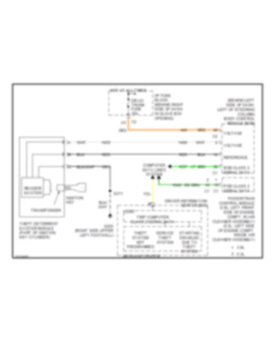
Pass-Key Wiring Diagram for Pontiac Grand Prix GT 2006
 https://portal-diagnostov.com/license.html
Automotive Electricians Portal FZCO
Automotive Electricians Portal FZCO
https://portal-diagnostov.com/license.html
https://portal-diagnostov.com/license.html
Automotive Electricians Portal FZCO
Automotive Electricians Portal FZCOList of elements for Pass-Key Wiring Diagram for Pontiac Grand Prix GT 2006:
- (behind left side of dash, left of steering column) body control module (bcm)
- 3.8l
- 5.3l
- Bcm class 2 serial data
- Computer data lines system
- Dr lk/ trunk fuse 15a
- Driver information center (dic)
- G202 (right side upper left footwell)
- Hot at all times
- I/p fuse block (behind right side of dash, in glove box opening)
- Ignition key
- Logic
- Message center
- Pcm class 2 serial data
- Powertrain control module (3.8l: left front side of engine compt, in air cleaner assembly) (5.3l: left side of engine compt, inside air cleaner assembly)
- Reader/ exciter
- Reference
- S211
- Service theft system
- Starting disabled due to theft system
- Theft deterrent exciter module (part of ignition key cylinder)
- Theft system not programmed
- Transponder
- Trip computer class 2 serial data
- Voltage
BODY CONTROL MODULES
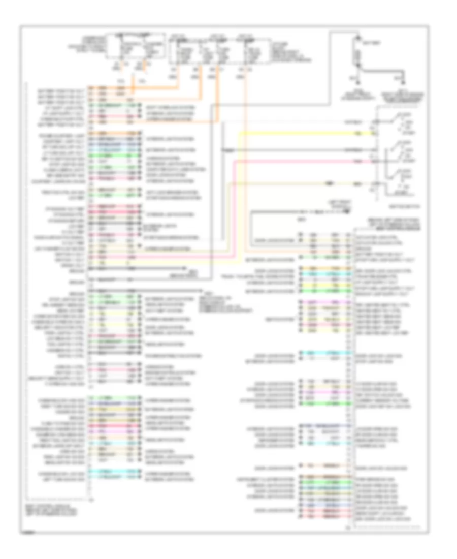
Body Control Modules Wiring Diagram for Pontiac Grand Prix GT 2006
 https://portal-diagnostov.com/license.html
Automotive Electricians Portal FZCO
Automotive Electricians Portal FZCO
https://portal-diagnostov.com/license.html
https://portal-diagnostov.com/license.html
Automotive Electricians Portal FZCO
Automotive Electricians Portal FZCOList of elements for Body Control Modules Wiring Diagram for Pontiac Grand Prix GT 2006:
- (behind left side of dash, left of steering column) body control module
- (below dash, on right side of steering column, on steering column support)
- (left front door sill) g301
- 10 volt ref
- 12 volt ref
- 3.8l
- 5.3l
- A/t shift lock ctrl
- A5 c2
- Acc
- Actuator lock ctrl
- Actuator unlock ctrl
- Anti-lock brakes system
- Anti-theft system
- Battery
- Battery positive volt
- Body control module (behind left side of dash, left of steering column)
- Chmsl/ bkup fuse 15a
- Class 2 serial data
- Computer data lines system
- Courtesy lamp volt
- Courtesy lamps sw on sig
- Crank volt
- Current sensor voltage
- Defogger system
- Dimmer sw high beam sig
- Door lock key sw lock sig
- Door lock sw lock sig
- Door lock sw unlock sig
- Door locks system
- Dr lk/ trunk fuse 15a
- Drl ambient sens sig
- Drv door lock sw lock sig
- Drv door lock unlock ctrl
- Drv heated seat low ref
- Drv heated seat rly ctrl
- E5 c1
- Engine controls system
- Exterior lamps off input
- Exterior lights system
- F wiper sw high sig
- Flash to pass sw sig
- Fog lamp rly ctrl
- Front fog lamp sw sig
- Fuse 15a
- G102 (right front of engine compt)
- G111 (right side of engine, on ignition control module bracket)
- G200 (behind radio)
- G201
- Ground
- Hazard sw sig
- Headlamp sw on sig
- Headlights system
- Heated seat low ref
- Heated seat rly ctrl
- Heated seat sens sig
- Highbeam rly ctrl
- Hood ajar switch signal
- Horn rly ctrl
- Horn sw sig
- Horns system
- Hot at all times
- I/p dimming ctrl
- I/p dimming return
- I/p dimming volt ref
- I/p fuse block (behind right side of dash, in glove box opening)
- Ignition 1 volt
- Ignition 3 volt
- Ignition switch
- Instrument cluster system
- Int light fuse 10a
- Interior lights system
- Key in ignition sw sig
- Key switch unlock sig
- Keyless entry sig
- Left turn sig sw sig
- Lf door ajar sw sig
- Lf door open sw sig
- Lf turn sig lmp volt
- Lock
- Low beam rly ctrl
- Low ref
- Low washer fluid ind sig
- Lr door ajar sw sig
- Lr door open sw sig
- Park brake sw sig
- Park lamp rly ctrl
- Park lamp sw on sig
- Pnk
- Power courtesy lamp
- Power distribution system
- Rap rly ctrl
- Rear compt lid ajar sw
- Rear defog rly ctrl
- Red
- Rf door ajar sw sig
- Rf door open sw sig
- Rf turn sig lmp volt
- Right turn sig sw sig
- Rr door ajar sw sig
- Rr door open sw sig
- S200
- S201
- S303
- Seats system
- Security indicator ctrl
- Sens low ref
- Shift interlock system
- Start
- Starting/charging system
- Stop lamp sw sig
- Stop lamp sw sog
- Tamper sw sig
- Tan
- Traction ctrl sw sig
- Trunk release ctrl
- Trunk, tailgate, fuel doors system
- Turn/ haz fuse 20a
- Underhood fuse block (mounted to right strut tower)
- Warning system
- Washer/ rvc fuse 6 15a
- Windshield pump ctrl
- Windshield sw high sig
- Windshield sw low sig
- Windshield washer sw sig
- Windshield wiper sw sig 2
- Wiper motor park sw sig
- Wiper/washer system
- Wsw/rvc
COMPUTER DATA LINES
Computer Data Lines Wiring Diagram for Pontiac Grand Prix GT 2006
 https://portal-diagnostov.com/license.html
Automotive Electricians Portal FZCO
Automotive Electricians Portal FZCO
https://portal-diagnostov.com/license.html
https://portal-diagnostov.com/license.html
Automotive Electricians Portal FZCO
Automotive Electricians Portal FZCOList of elements for Computer Data Lines Wiring Diagram for Pontiac Grand Prix GT 2006:
- (5.3l)
- (left side of rear compt) (if equipped) digital radio receiver
- (not used)
- 5.3l except 5.3l
- A11
- Abs/tcs class 2 serial data
- Adg class 2 serial data
- Automatic a/c
- B10
- Bcm class 2 serial data
- Body control module (bcm) (behind left side of dash, left of steering column)
- Class 2 serial data
- Data link connector (dlc) (under left side of dash, right of steering column)
- Driver information center (dic)
- Electronic brake control module (ebcm) (left side of engine compt, part of brake pressure modulator valve)
- G200 (behind radio)
- G202 (right side upper left footwell)
- Head-up display (hud) (if equipped)
- Hot at all times
- Hud class 2 serial data
- Hvac class 2 serial data
- Hvac control module
- I/p fuse block (behind right side of dash, in glove box opening)
- Inflatable restraint sensing & diagnostic module (sdm) (under right front seat)
- Instrument panel cluster (ipc)
- Ipc class 2 serial data
- Manual a/c
- Onstar/ aldl fuse 10a
- Pcm class 2 serial data
- Power distribution system
- Powertrain control module (pcm) (3.8l: left front side of engine compt, in air cleaner assembly) (5.3l: left side of engine compt, inside air cleaner assembly)
- Radio
- Radio class 2 serial data
- S211
- S213
- Sdm class 2 serial data
- Serial data +
- Serial data -
- Serial data bus (+)
- Serial data bus (-)
- Sp205 (clipped to knee- bolster panel, to right of data link connector)
- Steering angle sensor (in steering column)
- Tan
- Throttle actuator control (tac) module (3.8l: on throttle body) (5.3l: top rear of engine)
- Transmission control module (tcm) (5.3l) (left side of engine compt, inside air cleaner assembly)
- Trip computer class 2 serial data
- Uart serial data primary
- Uart serial data secondary
- Vehicle communication interface module (vcim) (if equipped) (in trunk, on left wheelwell)
- W/ abs
- W/ active control brake
COOLING FAN
3.8L VIN 2
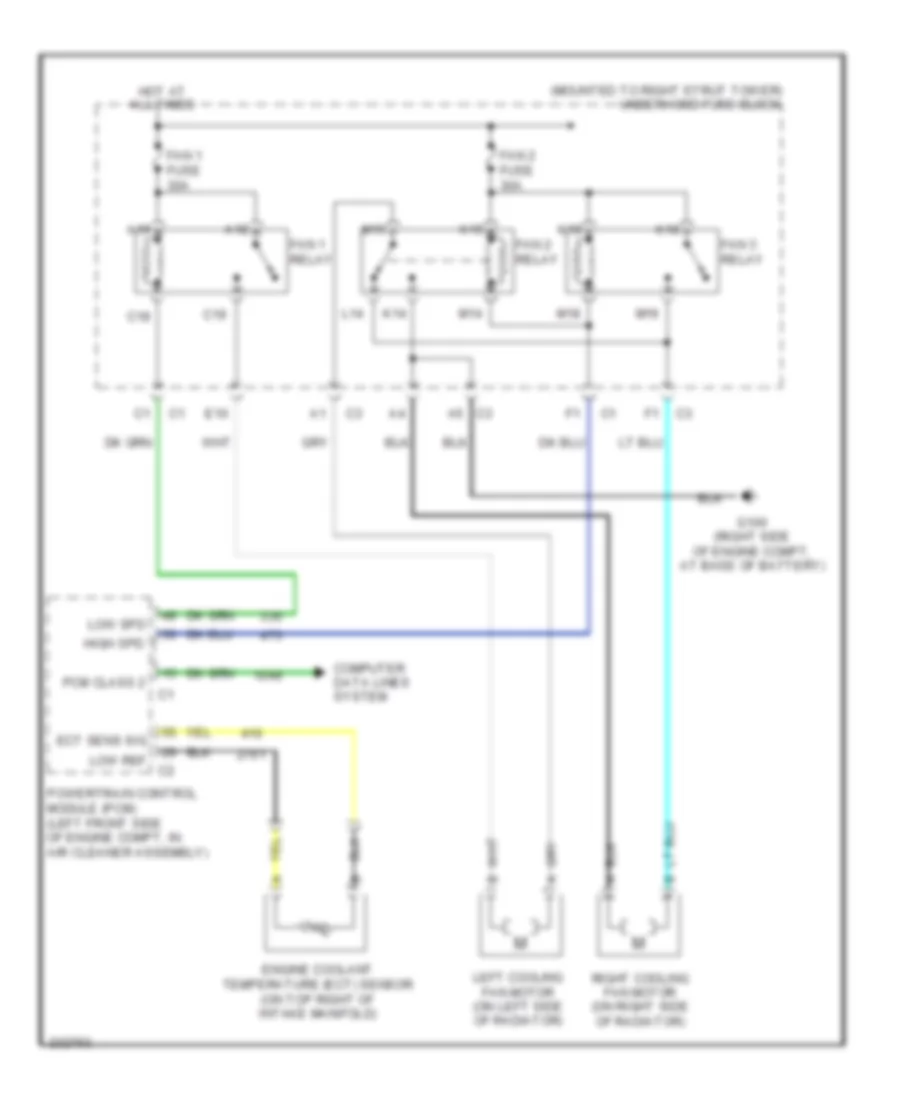
3.8L VIN 2, Cooling Fan Wiring Diagram for Pontiac Grand Prix GT 2006
 https://portal-diagnostov.com/license.html
Automotive Electricians Portal FZCO
Automotive Electricians Portal FZCO
https://portal-diagnostov.com/license.html
https://portal-diagnostov.com/license.html
Automotive Electricians Portal FZCO
Automotive Electricians Portal FZCOList of elements for 3.8L VIN 2, Cooling Fan Wiring Diagram for Pontiac Grand Prix GT 2006:
- (mounted to right strut tower) underhood fuse block
- A18
- A19
- C18
- C19
- Computer data lines system
- E10
- Ect sens sig
- Engine coolant temperature (ect) sensor (on top right of intake manifold)
- Fan 1 fuse 30a
- Fan 1 relay
- Fan 2 fuse 30a
- Fan 2 relay
- Fan 3 relay
- G100 (right side of engine compt, at base of battery)
- High spd
- Hot at all times
- K14
- K15
- K18
- K19
- L14
- Left cooling fan motor (on left side of radiator)
- Low ref
- Low spd
- M14
- M15
- M18
- M19
- Pcm class 2
- Powertrain control module (pcm) (left front side of engine compt, in air cleaner assembly)
- Right cooling fan motor (on right side of radiator)
3.8L VIN 4
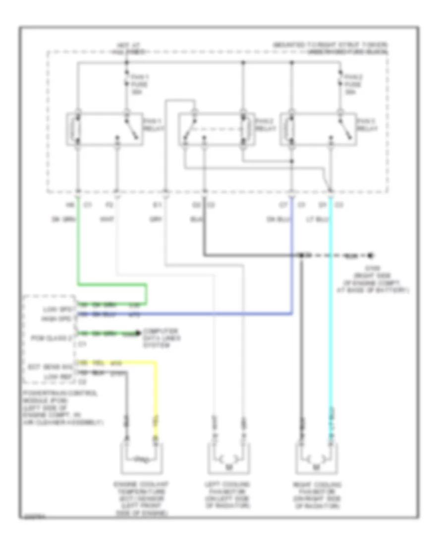
3.8L VIN 4, Cooling Fan Wiring Diagram for Pontiac Grand Prix GT 2006
 https://portal-diagnostov.com/license.html
Automotive Electricians Portal FZCO
Automotive Electricians Portal FZCO
https://portal-diagnostov.com/license.html
https://portal-diagnostov.com/license.html
Automotive Electricians Portal FZCO
Automotive Electricians Portal FZCOList of elements for 3.8L VIN 4, Cooling Fan Wiring Diagram for Pontiac Grand Prix GT 2006:
- (mounted to right strut tower) underhood fuse block
- A18
- A19
- C18
- C19
- Computer data lines system
- E10
- Ect sens sig
- Engine coolant temperature (ect) sensor (on top right of intake manifold)
- Fan 1 fuse 30a
- Fan 1 relay
- Fan 2 fuse 30a
- Fan 2 relay
- Fan 3 relay
- G100 (right side of engine compt, at base of battery)
- High spd
- Hot at all times
- K14
- K15
- K18
- K19
- L14
- Left cooling fan motor (on left side of radiator)
- Low ref
- Low spd
- M14
- M15
- M18
- M19
- Pcm class 2
- Powertrain control module (pcm) (left front side of engine compt, in air cleaner assembly)
- Right cooling fan motor (on right side of radiator)
5.3L VIN C
5.3L VIN C, Cooling Fan Wiring Diagram for Pontiac Grand Prix GT 2006
 https://portal-diagnostov.com/license.html
Automotive Electricians Portal FZCO
Automotive Electricians Portal FZCO
https://portal-diagnostov.com/license.html
https://portal-diagnostov.com/license.html
Automotive Electricians Portal FZCO
Automotive Electricians Portal FZCOList of elements for 5.3L VIN C, Cooling Fan Wiring Diagram for Pontiac Grand Prix GT 2006:
- (mounted to right strut tower) underhood fuse block
- Computer data lines system
- Ect sens sig
- Engine coolant temperature (ect) sensor (left front side of engine)
- Fan 1 fuse 30a
- Fan 1 relay
- Fan 2 fuse 30a
- Fan 2 relay
- Fan 3 relay
- G100 (right side of engine compt, at base of battery)
- High spd
- Hot at all times
- Left cooling fan motor (on left side of radiator)
- Low ref
- Low spd
- Pcm class 2
- Powertrain control module (pcm) (left side of engine compt, in air cleaner assembly)
- Right cooling fan motor (on right side of radiator)
- S123
CRUISE CONTROL
3.8L VIN 2
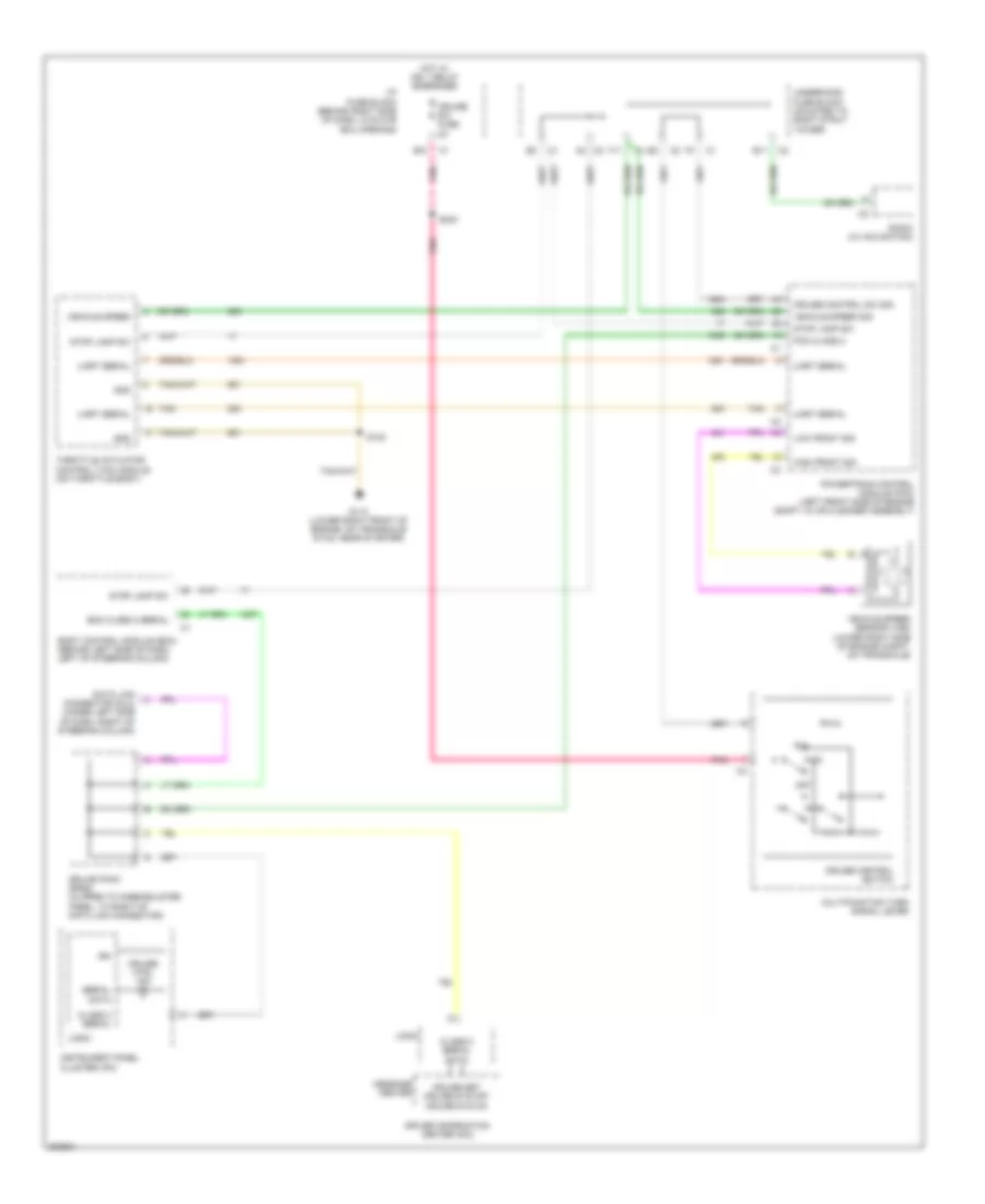
3.8L VIN 2, Cruise Control Wiring Diagram for Pontiac Grand Prix GT 2006
 https://portal-diagnostov.com/license.html
Automotive Electricians Portal FZCO
Automotive Electricians Portal FZCO
https://portal-diagnostov.com/license.html
https://portal-diagnostov.com/license.html
Automotive Electricians Portal FZCO
Automotive Electricians Portal FZCOList of elements for 3.8L VIN 2, Cruise Control Wiring Diagram for Pontiac Grand Prix GT 2006:
- B11
- Bcm class 2 serial
- Body control module (bcm) (behind left side of dash, left of steering column)
- Class 2 serial
- Class 2 serial data
- Cruise control sw sig
- Cruise control switch
- Cruise ctrl ind
- Cruise set cruise sys off cruise sys on
- Cruise sw fuse 2a
- Data link connector (dlc) (under left side of dash, right of steering column)
- Driver information center (dic)
- E12
- F11
- G113 (lower right front of engine, on transaxle stud, near starter)
- Gnd
- High front sig
- Hot w/ ign 1 relay energized
- I/p fuse block (behind right side of dash, in glove box opening)
- Ign
- Instrument panel cluster (ipc)
- Logic
- Low front sig
- Message center
- Multifunction turn signal lever
- Off
- Pcm class 2
- Pnk
- Powertrain control module (pcm) (left front side of engine compt, in air cleaner assembly)
- R/a
- Radio (w/ navigation)
- S102
- S240
- Serial data
- Splice pack sp205 (clipped to knee-bolster panel, to right of data link connector)
- Stop lamp sw
- Tan
- Throttle actuator control (tac) module (on throttle body)
- Uart serial
- Underhood fuse block (mounted to right strut tower)
- Vehicle speed
- Vehicle speed sensor (vss) (lower right side of engine compt, on transaxle)
- Vehicle speed sig
3.8L VIN 4
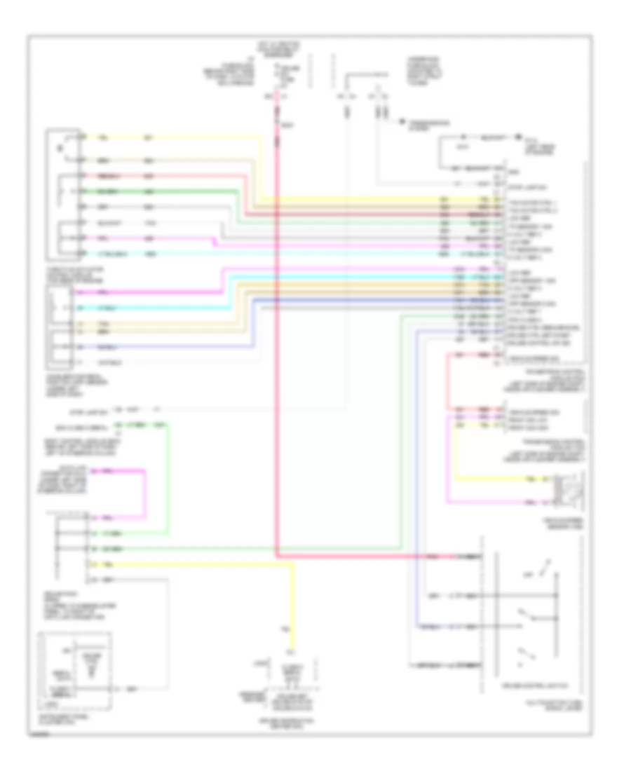
3.8L VIN 4, Cruise Control Wiring Diagram for Pontiac Grand Prix GT 2006
 https://portal-diagnostov.com/license.html
Automotive Electricians Portal FZCO
Automotive Electricians Portal FZCO
https://portal-diagnostov.com/license.html
https://portal-diagnostov.com/license.html
Automotive Electricians Portal FZCO
Automotive Electricians Portal FZCOList of elements for 3.8L VIN 4, Cruise Control Wiring Diagram for Pontiac Grand Prix GT 2006:
- B11
- Bcm class 2 serial
- Body control module (bcm) (behind left side of dash, left of steering column)
- Class 2 serial
- Class 2 serial data
- Cruise control sw sig
- Cruise control switch
- Cruise ctrl ind
- Cruise set cruise sys off cruise sys on
- Cruise sw fuse 2a
- Data link connector (dlc) (under left side of dash, right of steering column)
- Driver information center (dic)
- E12
- F11
- G113 (lower right front of engine, on transaxle stud, near starter)
- Gnd
- High front sig
- Hot w/ ign 1 relay energized
- I/p fuse block (behind right side of dash, in glove box opening)
- Ign
- Instrument panel cluster (ipc)
- Logic
- Low front sig
- Message center
- Multifunction turn signal lever
- Off
- Pcm class 2
- Pnk
- Powertrain control module (pcm) (left front side of engine compt, in air cleaner assembly)
- R/a
- Radio (w/ navigation)
- S102
- S240
- Serial data
- Splice pack sp205 (clipped to knee-bolster panel, to right of data link connector)
- Stop lamp sw
- Tan
- Throttle actuator control (tac) module (on throttle body)
- Uart serial
- Underhood fuse block (mounted to right strut tower)
- Vehicle speed
- Vehicle speed sensor (vss) (lower right side of engine compt, on transaxle)
- Vehicle speed sig
5.3L VIN C
5.3L VIN C, Cruise Control Wiring Diagram for Pontiac Grand Prix GT 2006
 https://portal-diagnostov.com/license.html
Automotive Electricians Portal FZCO
Automotive Electricians Portal FZCO
https://portal-diagnostov.com/license.html
https://portal-diagnostov.com/license.html
Automotive Electricians Portal FZCO
Automotive Electricians Portal FZCOList of elements for 5.3L VIN C, Cruise Control Wiring Diagram for Pontiac Grand Prix GT 2006:
- 5 volt ref 1
- 5 volt ref 2
- Accelerator pedal position (app) sensor (under left side of dash)
- App sensor 1 sig
- App sensor 2 sig
- Bcm class 2 serial
- Body control module (bcm) (behind left side of dash, left of steering column)
- Class 2 serial
- Class 2 serial data
- Cruise control sw sig
- Cruise control switch
- Cruise ctrl ind
- Cruise ctrl resume/accel
- Cruise ctrl set/coast
- Cruise set cruise sys off cruise sys on
- Cruise sw fuse 2a
- Data link connector (dlc) (under left side of dash, right of steering column)
- Driver information center (dic)
- E12
- Front sig high
- Front sig low
- G113 (left rear of engine)
- Gnd
- Hot w/ ignition main pcb relay energized
- I/p fuse block (behind right side of dash, in glove box opening)
- Ign
- Instrument panel cluster (ipc)
- Logic
- Low ref
- Message center
- Multifunction turn signal lever
- Nca
- Off
- Pcm class 2
- Pnk
- Powertrain control module (pcm) (left side of engine compt, inside air cleaner assembly)
- Red
- S101
- S240
- Serial data
- Splice pack sp205 (clipped to knee-bolster panel, to right of data link connector)
- Stop lamp sw
- Tac motor ctrl 1
- Tac motor ctrl 2
- Tan
- Throttle actuator control module (top rear of engine)
- Tp sensor 1 sig
- Tp sensor 2 sig
- Transmission control module (tcm) (left side of engine compt, inside air cleaner assembly)
- Transmissions system
- Underhood fuse block (mounted to right strut tower)
- Vehicle speed sensor (vss)
- Vehicle speed sig
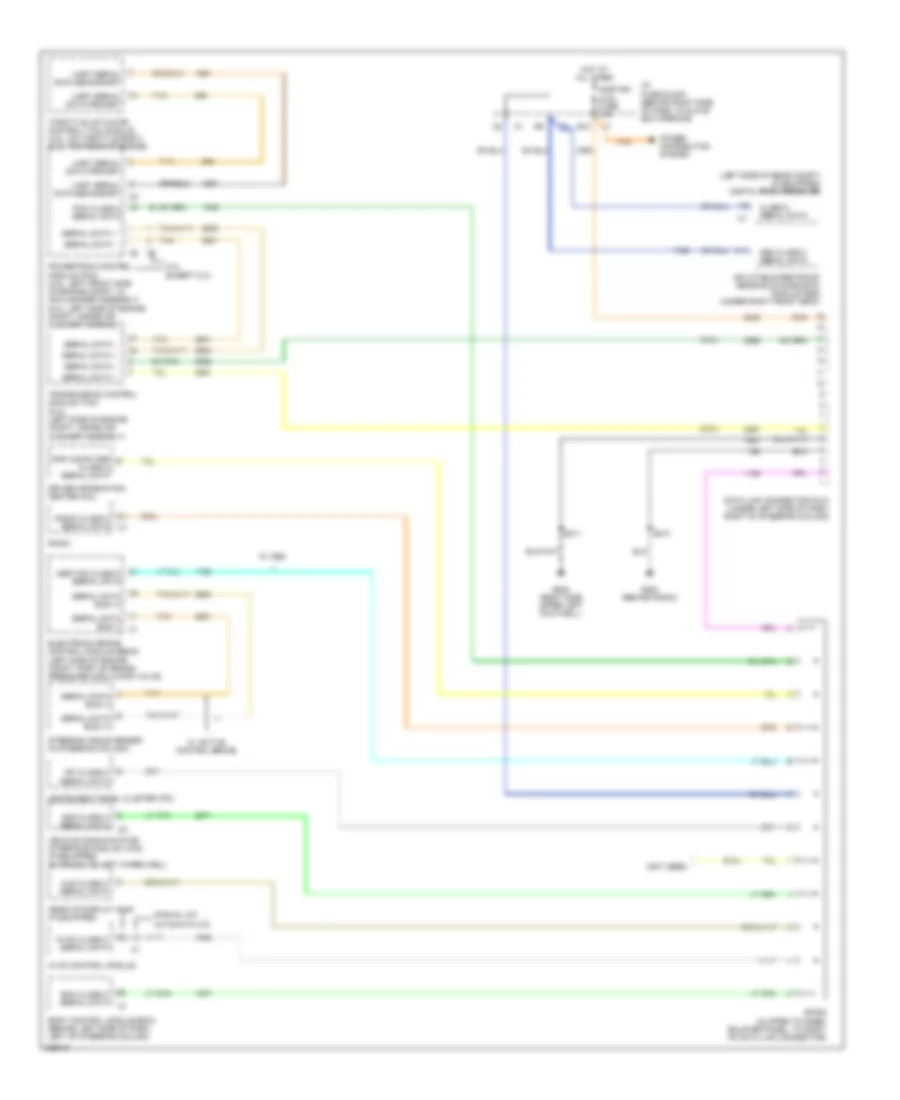
DEFOGGERS
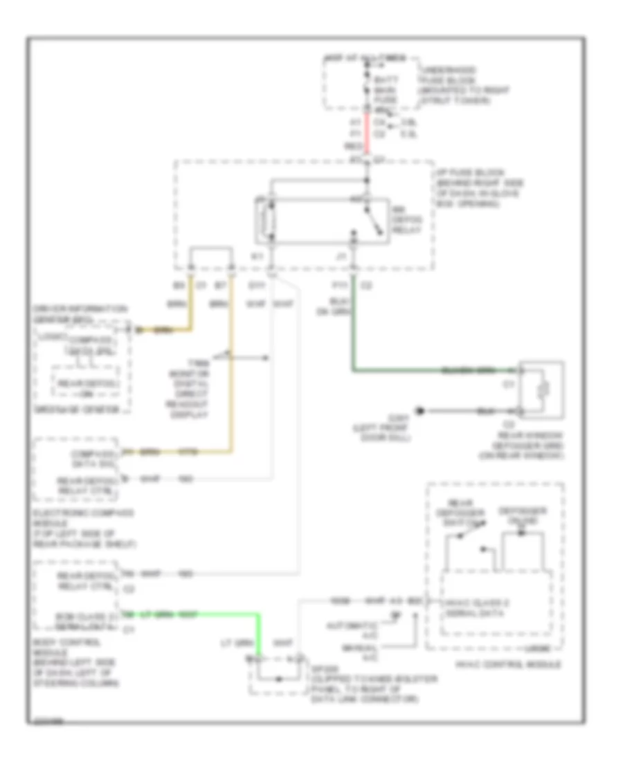
Defoggers Wiring Diagram for Pontiac Grand Prix GT 2006
 https://portal-diagnostov.com/license.html
Automotive Electricians Portal FZCO
Automotive Electricians Portal FZCO
https://portal-diagnostov.com/license.html
https://portal-diagnostov.com/license.html
Automotive Electricians Portal FZCO
Automotive Electricians Portal FZCOList of elements for Defoggers Wiring Diagram for Pontiac Grand Prix GT 2006:
- 3.8l
- 5.3l
- Automatic a/c
- Batt main fuse 40a
- Bcm class 2 serial data c1
- Body control module (behind left side of dash, left of steering column)
- Compass data sig
- D11
- Defogger on ind
- Driver information center (dic)
- Electronic compass module (top left side of rear package shelf)
- F11
- G301 (left front door sill)
- Hot at all times
- Hvac class 2 serial data
- Hvac control module
- I/p fuse block (behind right side of dash, in glove box opening)
- Logic
- Manual a/c
- Message center
- Rear defog on
- Rear defog relay ctrl
- Rear defog relay ctrl c2
- Rear defogger switch
- Rear window defogger grid (on rear window)
- Red
- Rr defog relay
- Sp205 (clipped to knee-bolster panel, to right of data link connector)
- Trim monitor digital direct readout display
- Underhood fuse block (mounted to right strut tower)
ELECTRONIC POWER STEERING
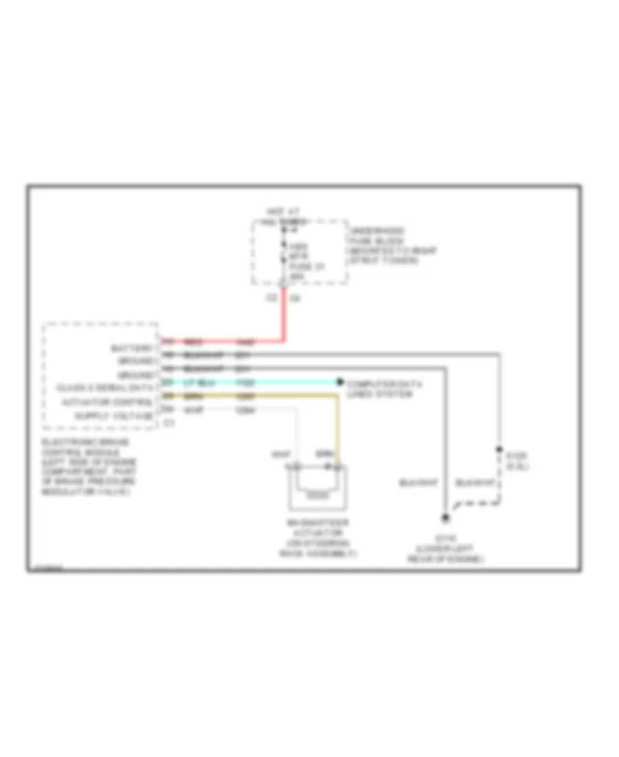
Electronic Power Steering Wiring Diagram for Pontiac Grand Prix GT 2006
 https://portal-diagnostov.com/license.html
Automotive Electricians Portal FZCO
Automotive Electricians Portal FZCO
https://portal-diagnostov.com/license.html
https://portal-diagnostov.com/license.html
Automotive Electricians Portal FZCO
Automotive Electricians Portal FZCOList of elements for Electronic Power Steering Wiring Diagram for Pontiac Grand Prix GT 2006:
- Abs mtr fuse 31 40a
- Actuator control
- Battery
- Class 2 serial data
- Computer data lines system
- Electronic brake control module (left side of engine compartment, part of brake pressure modulator valve)
- G115 (lower left rear of engine)
- Ground
- Hot at all times
- Magnasteer actuator (on steering rack assembly)
- Red
- S125 (5.3l)
- Underhood fuse block (mounted to right strut tower)
ENGINE PERFORMANCE
3.8L VIN 2
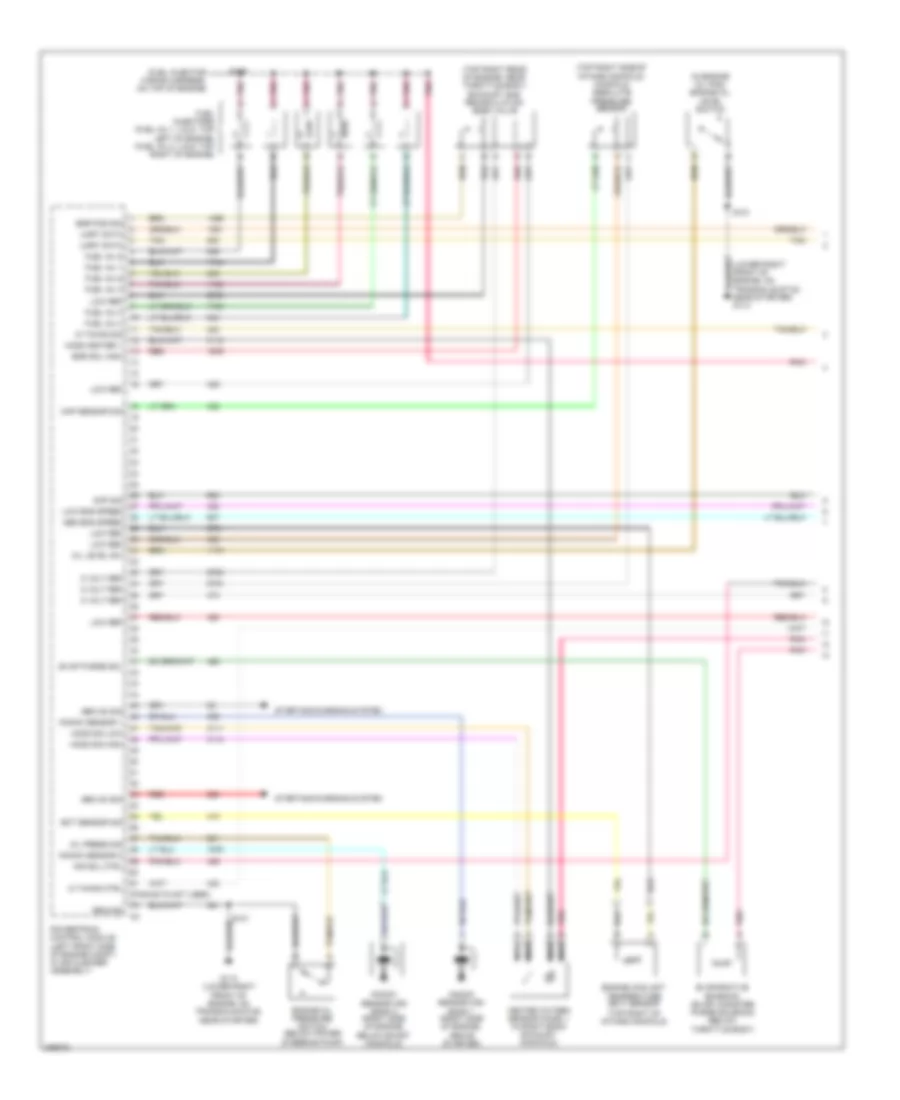
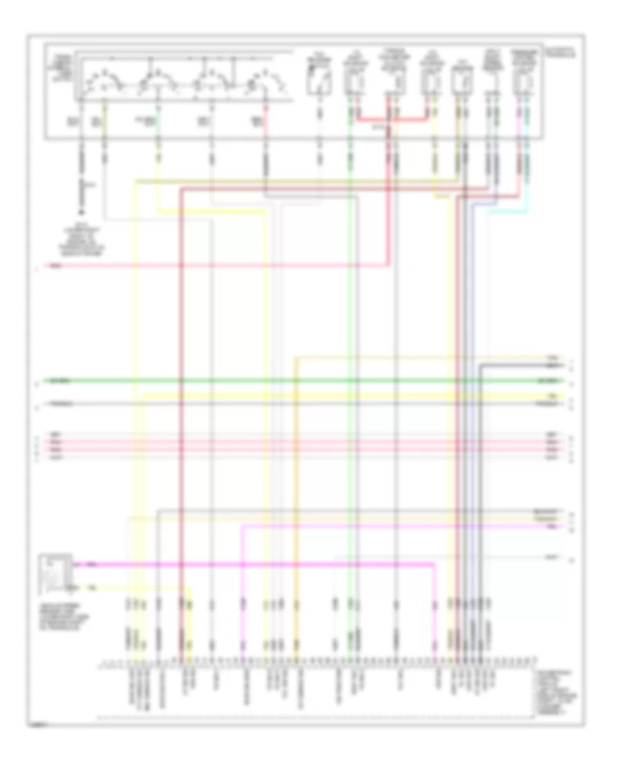
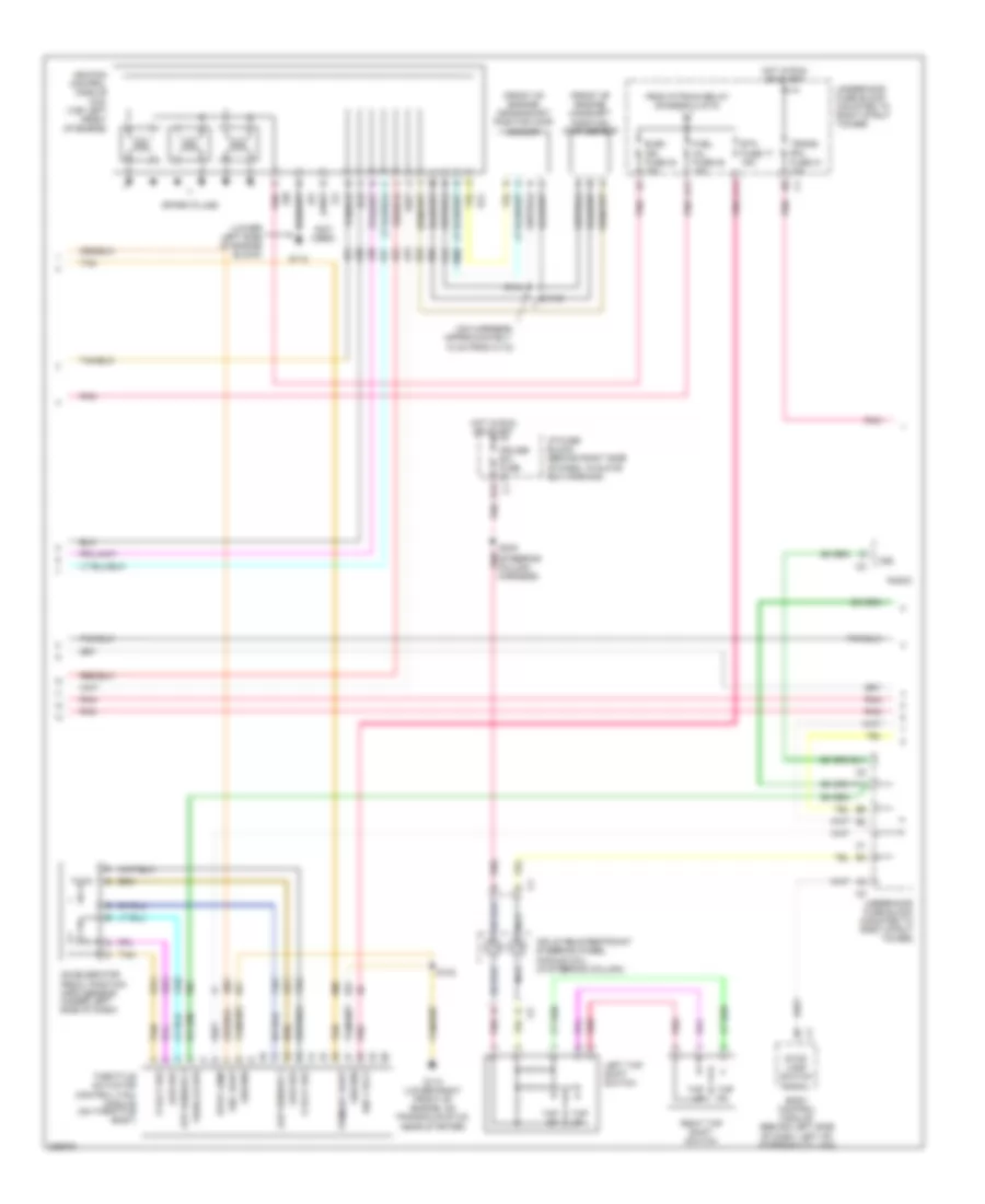
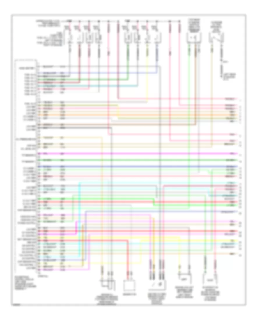
3.8L VIN 2, Engine Performance Wiring Diagram (1 of 5) for Pontiac Grand Prix GT 2006
 https://portal-diagnostov.com/license.html
Automotive Electricians Portal FZCO
Automotive Electricians Portal FZCO
https://portal-diagnostov.com/license.html
https://portal-diagnostov.com/license.html
Automotive Electricians Portal FZCO
Automotive Electricians Portal FZCOList of elements for 3.8L VIN 2, Engine Performance Wiring Diagram (1 of 5) for Pontiac Grand Prix GT 2006:
- (fuel injector wiring harness, on top of engine)
- (in engine oil pan) engine oil level switch
- (lower right front of engine, on transaxle stud, near starter) g113
- (pins 62-72 not used)
- (top right of intake manifold)
- (top right rear of engine, near throttle body) exhaust gas recirculation (egr) valve
- (top right side of intake manifold) manifold absolute pressure sensor
- 5 volt ref
- Air sol ctrl
- Cmp sig
- Ect sensor sig
- Egr pos sig
- Egr sol high
- Engine coolant temperature (ect) sensor
- Engine oil pressure switch (below power steering pump)
- Evap purge sol
- Evaporative emission (evap) canister purge solenoid (below throttle body)
- Fuel inj 1
- Fuel inj 2
- Fuel inj 3
- Fuel inj 4
- Fuel inj 5
- Fuel inj 6
- Fuel injectors (fuel inj 1, 3 & 5: top left of engine) (fuel inj 2, 4 & 6: top right of engine)
- G113 (lower right front of engine, on transaxle stud, near starter)
- Gen on sig
- Ground
- Heated oxygen sensor (ho2s) 1 (in right bank exhaust manifold)
- Ho2s heater 1
- Ho2s sig high
- Ho2s sig low
- Ic timing ctrl
- Ic timing sig
- Knock sensor (ks) bank 1 (right side of engine, above starter)
- Knock sensor (ks) bank 2 (right side of engine, below exhst manifold)
- Knock sensor 1
- Knock sensor 2
- Low eng speed
- Low ref
- Map sensor sig
- Med eng speed
- Nca
- Oil level sw
- Oil press sig
- Pnk
- Powertrain control module (left front side of engine compt, in air cleaner assembly)
- Red
- S101
- S109
- Starting/charging system
- Tan
- Uart data
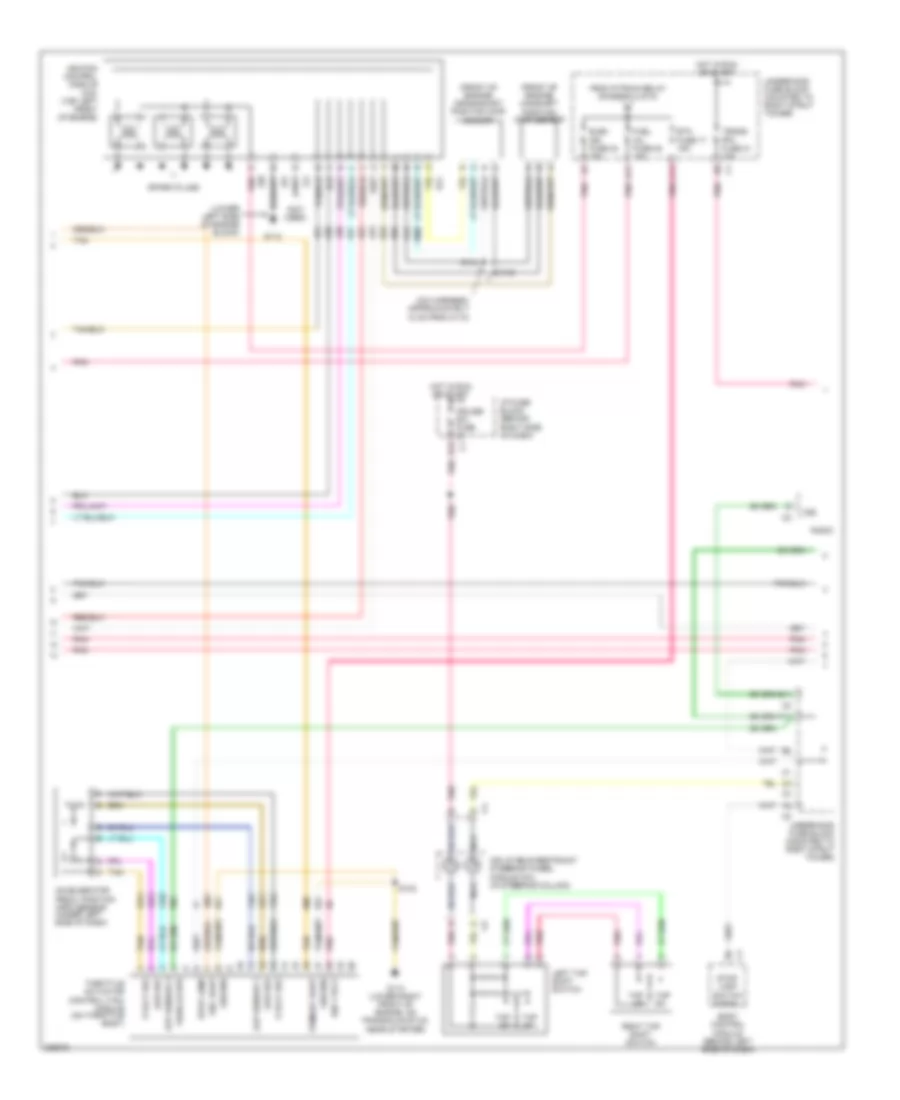
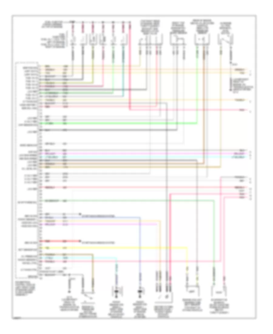
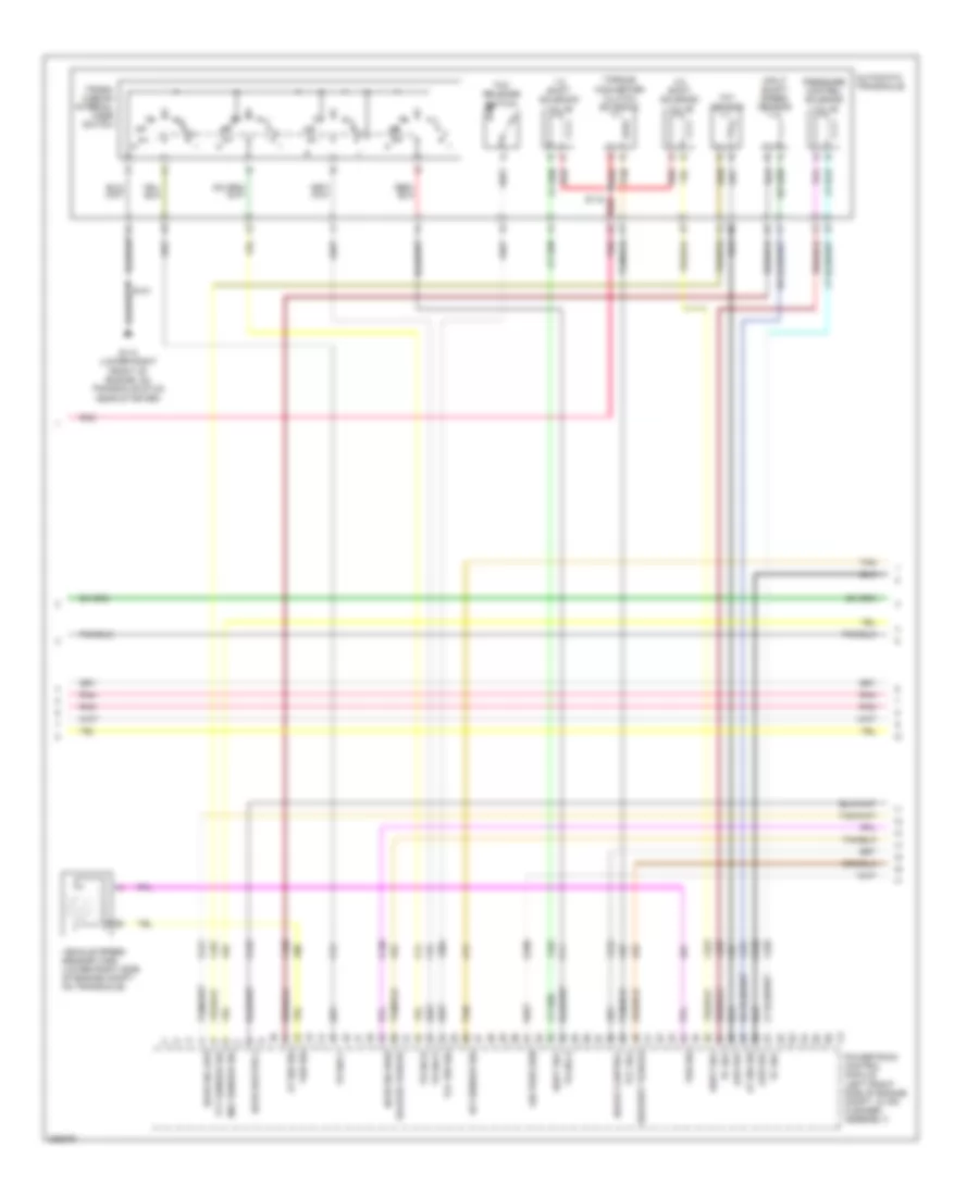
3.8L VIN 2, Engine Performance Wiring Diagram (2 of 5) for Pontiac Grand Prix GT 2006
 https://portal-diagnostov.com/license.html
Automotive Electricians Portal FZCO
Automotive Electricians Portal FZCO
https://portal-diagnostov.com/license.html
https://portal-diagnostov.com/license.html
Automotive Electricians Portal FZCO
Automotive Electricians Portal FZCOList of elements for 3.8L VIN 2, Engine Performance Wiring Diagram (2 of 5) for Pontiac Grand Prix GT 2006:
- (front of engine) camshaft position (cmp) sensor
- (front of engine) crankshaft position (ckp) sensor
- (icm harness, approximately 12 cm from c110)
- (lower left side of engine block)
- (not used)
- 5 volt ref
- A11
- Aap sensor 1
- Accelerator pedal position (app) sensor (under left side of dash)
- App sensor 2
- B11
- Body control module (behind left side of dash)
- C11
- Cruise sw fuse 2a
- E12
- Elek ign fuse 24 15a
- Etc fuse 17 15a
- F11
- From p/train relay (diagram 4 of 5)
- Fuel inj fuse 20 15a
- G112
- G113 (lower right front of engine, on transaxle stud, near starter)
- Ground
- Hot in run or start
- I/p fuse block (behind right side of dash)
- Ign 1 volt
- Ignition control module (icm) (top left front of engine)
- Inflatable restraint steering wheel module coil (in steering column)
- Left tap shift switch
- Low ref
- Nca
- Pnk
- Primary uart
- Radio
- Right tap shift switch
- S102
- S144
- S145
- Sec uart
- Spark plugs
- Stop lamp
- Stop lamp switch signal
- Tan
- Tap dn
- Tap up
- Throttle actuator control (tac) module (on throttle body)
- Trans sol fuse 21 10a
- Underhood fuse block (mounted to right strut tower)
- Vehicle spd
- Vss
3.8L VIN 2, Engine Performance Wiring Diagram (3 of 5) for Pontiac Grand Prix GT 2006
 https://portal-diagnostov.com/license.html
Automotive Electricians Portal FZCO
Automotive Electricians Portal FZCO
https://portal-diagnostov.com/license.html
https://portal-diagnostov.com/license.html
Automotive Electricians Portal FZCO
Automotive Electricians Portal FZCOList of elements for 3.8L VIN 2, Engine Performance Wiring Diagram (3 of 5) for Pontiac Grand Prix GT 2006:
- 1-2 shift solenoid valve
- 2-3 shift solenoid valve
- Air pres sen
- At iss sig
- Automatic transaxle
- G113 (lower right front of engine, on transaxle stud, near starter)
- Ho2s heater 2
- Ho2s sig high
- Ho2s sig low
- Iat sensor sig
- Input shaft speed sensor
- Low ref
- Maf sensor sig
- Pc sol
- Pnk
- Powertrain control module (left front side of engine compt, in air cleaner assembly)
- Pressure control solenoid valve
- Red
- S115
- Shift sol
- Tan
- Tcc release switch
- Tcc sol
- Tcc sw sig
- Tft sensor
- Tft sensor sig
- Torque converter clutch solenoid
- Tr sw a
- Tr sw b
- Tr sw c
- Tr sw p
- Trans- mission internal mode switch
- Vehicle speed sensor (vss) (lower right side of engine compt, on transaxle)
- Vss sig
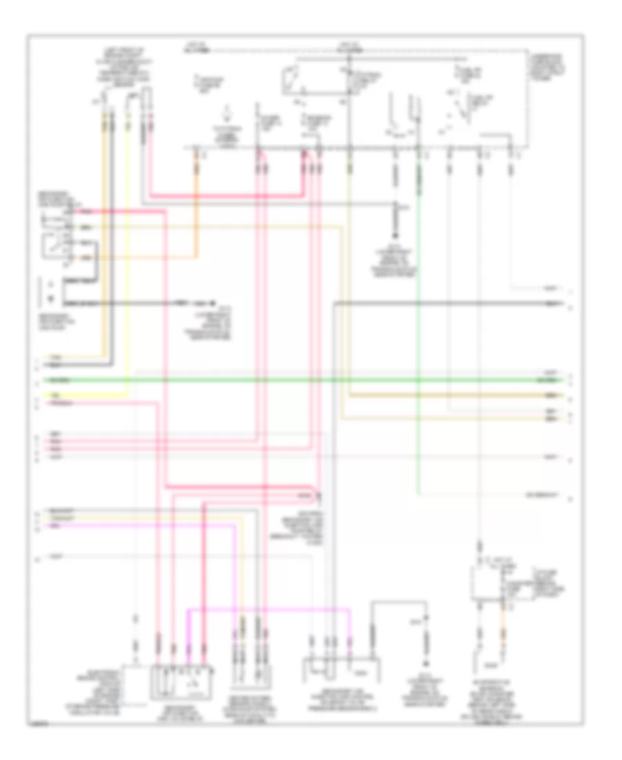
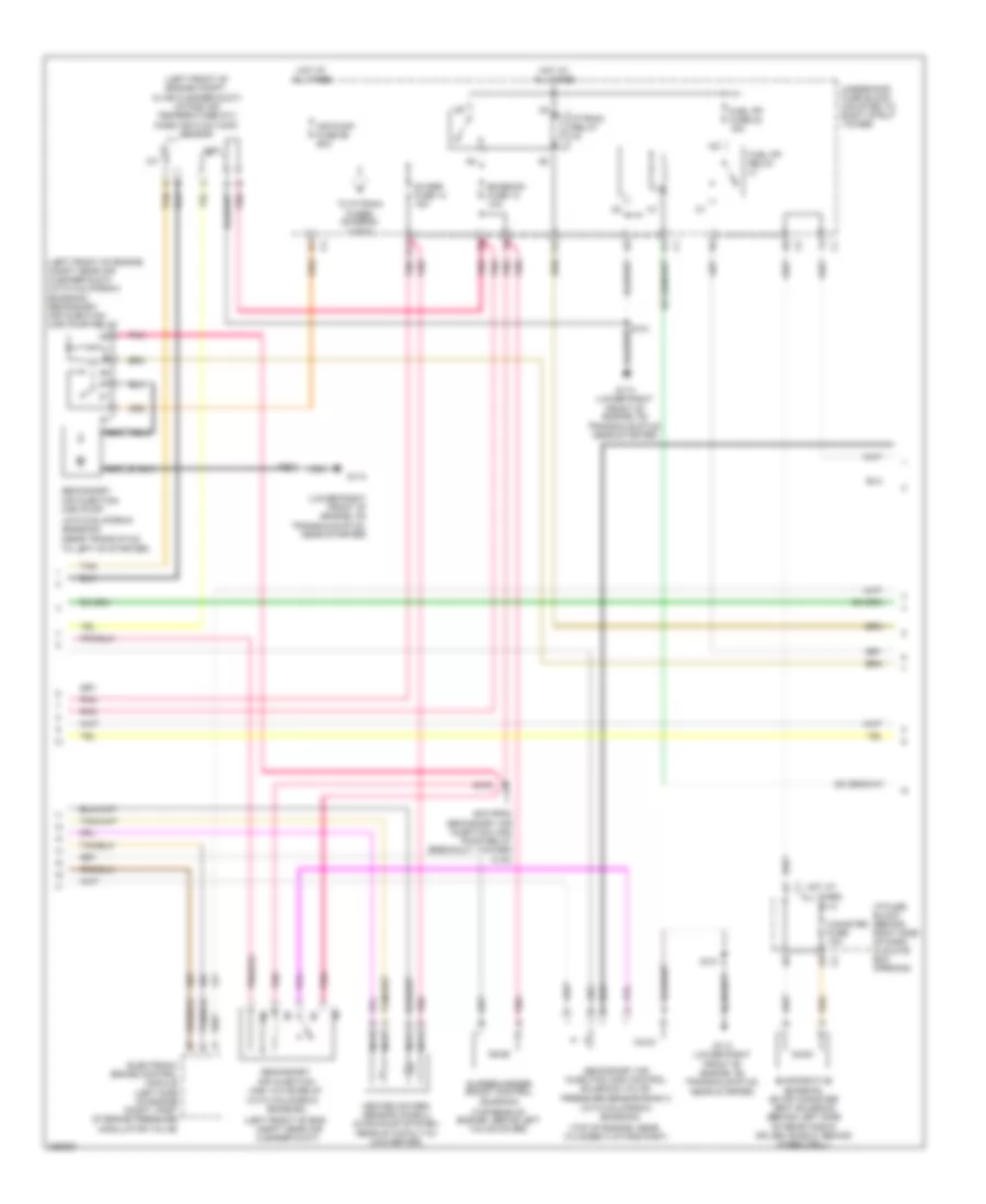
3.8L VIN 2, Engine Performance Wiring Diagram (4 of 5) for Pontiac Grand Prix GT 2006
 https://portal-diagnostov.com/license.html
Automotive Electricians Portal FZCO
Automotive Electricians Portal FZCO
https://portal-diagnostov.com/license.html
https://portal-diagnostov.com/license.html
Automotive Electricians Portal FZCO
Automotive Electricians Portal FZCOList of elements for 3.8L VIN 2, Engine Performance Wiring Diagram (4 of 5) for Pontiac Grand Prix GT 2006:
- (left front of engine compt, in air cleaner duct) intake air temperature(iat)/ mass air flow (maf) sensor
- 5cm from secondary air injection (air) pump relay breakout, toward c1000)
- A nca
- Air pump fuse 56 50a
- B nca
- Canister fuse 10a
- D11
- Electronic brake control module (left side of engine compt, part of brake pressure modulator valve)
- Emission fuse 12 10a
- Evaporative emission (evap) canister vent solenoid (behind left side of rear fascia splash shield, behind wheelwell)
- F12
- Fuel pp fuse 22 15a
- Fuel pp relay
- G113 (lower right front of engine, on transaxle stud, near starter)
- Heated oxygen sensor (ho2s) 2 (in exhaust system, rear of catalytic converter)
- Hot at all times
- I/p fuse block (behind right side of dash)
- Iat
- Maf
- Nca
- O2 ssr fuse 14 15a
- P/train relay
- Pnk
- S101
- S103
- S104
- Secondary air injection (air) control solenoid valve/ pressure sensor bank 2
- Secondary air injection (air) pump
- Secondary air injection (air) pump relay
- Secondary air injection (air) valve relay
- Tan
- To p/train fuses (diagram 2 of 5)
- Underhood fuse block (mounted to right strut tower)
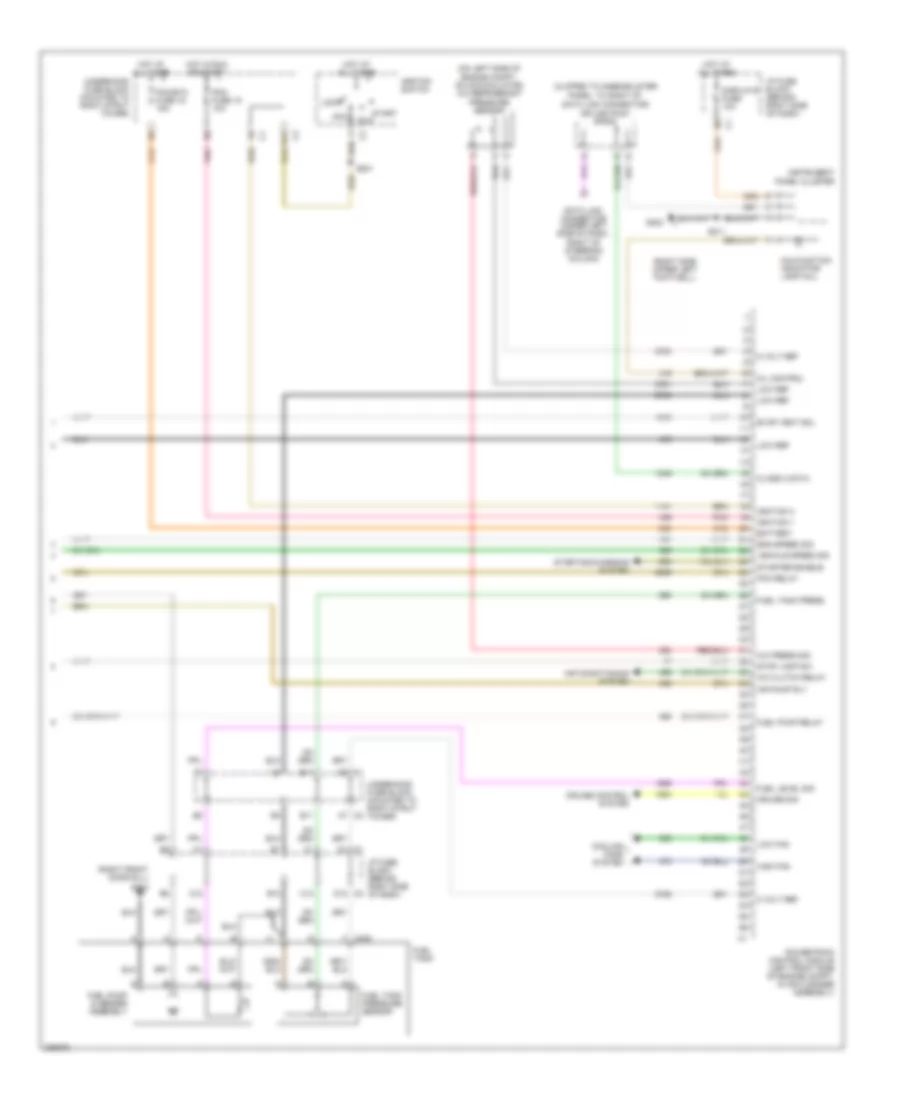
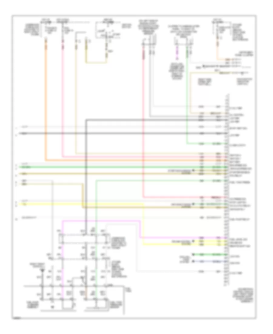
3.8L VIN 2, Engine Performance Wiring Diagram (5 of 5) for Pontiac Grand Prix GT 2006
 https://portal-diagnostov.com/license.html
Automotive Electricians Portal FZCO
Automotive Electricians Portal FZCO
https://portal-diagnostov.com/license.html
https://portal-diagnostov.com/license.html
Automotive Electricians Portal FZCO
Automotive Electricians Portal FZCOList of elements for 3.8L VIN 2, Engine Performance Wiring Diagram (5 of 5) for Pontiac Grand Prix GT 2006:
- (clipped to knee-bolster panel, to right of data link connector)
- (on left side of engine compt, on accumulator) a/c refrigerant pressure sensor
- (right front door sill)
- (right side upper left footwell)
- 5 volt ref
- A/c clutch relay
- A/c press sig
- A12
- A7 c2
- Acc
- Air conditioning system
- Air pump rly
- B12
- Battery
- C1 d8
- C12
- Class 2 data
- Cooling fans system
- Cruise control system
- Cruise sig
- D1 c1
- D11
- D12 c2
- Data link connector (under left side of dash, right of steering column)
- Displays fuse 10a
- E11
- Eng speed sig
- Evap vent sol
- F c405
- Fuel level sig
- Fuel pump & sender assembly
- Fuel pump relay
- Fuel tank
- Fuel tank press
- Fuel tank pressure sensor
- G202
- G302
- High fan
- Hot at all times
- Hot in run or start
- I/p fuse block (behind right side of dash)
- Ignition 1
- Ignition 3
- Ignition switch
- Instrument panel cluster
- Lock
- Low fan
- Low ref
- Malfunction indicator lamp (mil)
- Mil control
- Pcm fuse 15 10a
- Pcm relay
- Pcm/etc fuse 16 15a
- Pnk
- Powertrain control module (left front side of engine compt, in air cleaner assembly)
- Run
- S201
- S211
- Splice pack sp205
- Start
- Starter enable
- Starting/charging system
- Stop lamp sw
- Underhood fuse block (mounted to right strut tower)
- Vehicle speed sig
3.8L VIN 4
3.8L VIN 4, Engine Performance Wiring Diagram (1 of 5) for Pontiac Grand Prix GT 2006
 https://portal-diagnostov.com/license.html
Automotive Electricians Portal FZCO
Automotive Electricians Portal FZCO
https://portal-diagnostov.com/license.html
https://portal-diagnostov.com/license.html
Automotive Electricians Portal FZCO
Automotive Electricians Portal FZCOList of elements for 3.8L VIN 4, Engine Performance Wiring Diagram (1 of 5) for Pontiac Grand Prix GT 2006:
- (fuel injector wiring harness, on top of engine)
- (in engine oil pan) engine oil level switch
- (lower right front of engine, on transaxle stud, near starter) g113
- (pins 62-72 not used)
- (rear of engine, above valve cover) manifold absolute pressure sensor
- (right top of engine)
- (top right of intake manifold)
- (top right rear of engine, near throttle body) exhaust gas recirculation (egr) valve
- 5 volt ref
- Air sol ctrl
- Baro sens sig
- Barometric pressure (baro) sensor
- Cmp sig
- Ect sensor sig
- Egr pos sig
- Egr sol high
- Engine coolant temperature (ect) sensor
- Engine oil pressure switch (below power steering pump)
- Evap purge sol
- Evaporative emission (evap) canister purge solenoid (below throttle body)
- Fuel inj 1
- Fuel inj 2
- Fuel inj 3
- Fuel inj 4
- Fuel inj 5
- Fuel inj 6
- Fuel injectors (fuel inj 1, 3 & 5: top left of engine) (fuel inj 2, 4 & 6: top right of engine)
- G113 (lower right front of engine, on transaxle stud, near starter)
- Gen on sig
- Ground
- Heated oxygen sensor (ho2s) 1 (in right bank exhaust manifold)
- Ho2s heater 1
- Ho2s sig high
- Ho2s sig low
- Ic timing ctrl
- Ic timing sig
- Knock sensor (ks) bank 1 (right side of engine, above starter)
- Knock sensor (ks) bank 2 (right side of engine, below exhst manifold)
- Knock sensor 1
- Knock sensor 2
- Low eng speed
- Low ref
- Map sensor sig
- Med eng speed
- Nca
- Oil level sw
- Oil press sig
- Pnk
- Powertrain control module (left front side of engine compt, in air cleaner assembly)
- Red
- S101
- S109
- Starting/charging system
- Tan
- Uart data
3.8L VIN 4, Engine Performance Wiring Diagram (2 of 5) for Pontiac Grand Prix GT 2006
 https://portal-diagnostov.com/license.html
Automotive Electricians Portal FZCO
Automotive Electricians Portal FZCO
https://portal-diagnostov.com/license.html
https://portal-diagnostov.com/license.html
Automotive Electricians Portal FZCO
Automotive Electricians Portal FZCOList of elements for 3.8L VIN 4, Engine Performance Wiring Diagram (2 of 5) for Pontiac Grand Prix GT 2006:
- (front of engine) camshaft position (cmp) sensor
- (front of engine) crankshaft position (ckp) sensor
- (icm harness, approximately 12 cm from c110)
- (lower left side of engine block)
- (not used)
- (steering column pnk harness)
- 5 volt ref
- A11
- Aap sensor 1
- Accelerator pedal position (app) sensor (under left side of dash)
- App sensor 2
- B11
- Body control module (behind left side of dash, left of) steering column)
- C11
- Cruise sw fuse 2a
- E12
- Elek ign fuse 24 15a
- Etc fuse 17 15a
- F11
- From p/train relay (diagram 4 of 5)
- Fuel inj fuse 20 15a
- G112
- G113 (lower right front of engine, on transaxle stud, near starter)
- Ground
- Hot in run or start
- I/p fuse block (behind right side of dash, in glove box opening)
- Ign 1 volt
- Ignition control module (icm) (top left front of engine)
- Inflatable restraint steering wheel module coil (in steering column)
- Left tap shift switch
- Low ref
- Nca
- Pnk
- Primary uart
- Radio
- Right tap shift switch
- S102
- S144
- S145
- S240
- Sec uart
- Spark plugs
- Stop lamp
- Stop lamp switch signal
- Tan
- Tap dn
- Tap up
- Throttle actuator control (tac) module (on throttle body)
- Trans sol fuse 21 10a
- Underhood fuse block (mounted to right strut tower)
- Vehicle spd
- Vss
3.8L VIN 4, Engine Performance Wiring Diagram (3 of 5) for Pontiac Grand Prix GT 2006
 https://portal-diagnostov.com/license.html
Automotive Electricians Portal FZCO
Automotive Electricians Portal FZCO
https://portal-diagnostov.com/license.html
https://portal-diagnostov.com/license.html
Automotive Electricians Portal FZCO
Automotive Electricians Portal FZCOList of elements for 3.8L VIN 4, Engine Performance Wiring Diagram (3 of 5) for Pontiac Grand Prix GT 2006:
- 1-2 shift solenoid valve
- 2-3 shift solenoid valve
- Air pres sen
- At iss sig
- Automatic transaxle
- Boost control
- Deliver torque
- G113 (lower right front of engine, on transaxle stud, near starter)
- Ho2s heater 2
- Ho2s sig high
- Ho2s sig low
- Iat sensor sig
- Input shaft speed sensor
- Low ref
- Maf sensor sig
- Pc sol
- Pnk
- Powertrain control module (left front side of engine compt, in air cleaner assembly)
- Pressure control solenoid valve
- Red
- Request torque
- S115
- Shift sol
- Tan
- Tcc release switch
- Tcc sol
- Tcc sw sig
- Tft sensor
- Tft sensor sig
- Torque converter clutch solenoid
- Tr sw a
- Tr sw b
- Tr sw c
- Tr sw p
- Trans- mission internal mode switch
- Vehicle speed sensor (vss) (lower right side of engine compt, on transaxle)
- Vss sig
3.8L VIN 4, Engine Performance Wiring Diagram (4 of 5) for Pontiac Grand Prix GT 2006
 https://portal-diagnostov.com/license.html
Automotive Electricians Portal FZCO
Automotive Electricians Portal FZCO
https://portal-diagnostov.com/license.html
https://portal-diagnostov.com/license.html
Automotive Electricians Portal FZCO
Automotive Electricians Portal FZCOList of elements for 3.8L VIN 4, Engine Performance Wiring Diagram (4 of 5) for Pontiac Grand Prix GT 2006:
- (left front of eng
- (left front of engine compt near air cleaner duct) (with california
- (left front of engine compt, in air cleaner duct) intake air temperature(iat)/ mass air flow (maf) sensor
- (lower right front of engine, on transaxle stud, near starter)
- (near trans stud, to left of starter)
- (top of engine, near
- (top rear of engine, above left valve cover)
- (with california
- (with california emission)
- 5cm from secondary air injection (air) pump relay breakout, toward c100)
- A nca
- Air pump fuse 56 50a
- B nca
- Canister fuse 10a
- Compt near air cleaner duct)
- Cylinder 4 intake port)
- D11
- Electronic brake control module (left side of engine compt, part of brake pressure modulator valve)
- Emission fuse 12 10a
- Emission)
- Emission) secondary air injection (air) pump relay
- Evaporative emission (evap) canister vent solenoid (behind left side of rear fascia splash shield, behind wheelwell)
- F12
- Fuel pp fuse 22 15a
- Fuel pp relay
- G113
- G113 (lower right front of engine, on transaxle stud, near starter)
- Heated oxygen sensor (ho2s) 2 (in exhaust system, rear of catalytic converter)
- Hot at all times
- I/p fuse block (behind right side of dash, in glove box opening)
- Iat
- Maf
- Nca
- O2 ssr fuse 14 15a
- P/train relay
- Pnk
- S101
- S103
- S104
- Secondary air injection (air) control solenoid valve/ pressure sensor bank 2
- Secondary air injection (air) pump
- Secondary air injection (air) valve relay
- Supercharger boost control solenoid
- Tan
- To p/train fuses (diagram 2 of 5)
- Underhood fuse block (mounted to right strut tower)
3.8L VIN 4, Engine Performance Wiring Diagram (5 of 5) for Pontiac Grand Prix GT 2006
 https://portal-diagnostov.com/license.html
Automotive Electricians Portal FZCO
Automotive Electricians Portal FZCO
https://portal-diagnostov.com/license.html
https://portal-diagnostov.com/license.html
Automotive Electricians Portal FZCO
Automotive Electricians Portal FZCOList of elements for 3.8L VIN 4, Engine Performance Wiring Diagram (5 of 5) for Pontiac Grand Prix GT 2006:
- (clipped to knee-bolster panel, to right of data link connector)
- (on left side of engine compt, on accumulator) a/c refrigerant pressure sensor
- (right front door sill)
- (right side upper left footwell)
- 5 volt ref
- A/c clutch relay
- A/c press sig
- A12
- A7 c2
- Acc
- Air conditioning system
- Air pump rly
- B12
- Battery
- C1 d8
- C12
- Class 2 data
- Cooling fans system
- Cruise control system
- Cruise sig
- D1 c1
- D10
- D11
- D12 c2
- Data link connector (under left side of dash, right of steering column)
- Displays fuse 10a
- E11
- Eng speed sig
- Evap vent sol
- F c405
- Fuel level sig
- Fuel pump & sender assembly
- Fuel pump relay
- Fuel tank
- Fuel tank press
- Fuel tank pressure sensor
- G202
- G302
- High fan
- Hot at all times
- Hot at hot at all times all times
- Hot in run or start
- I/p fuse block (behind right side of dash, in glove box opening)
- Ignition 1
- Ignition 3
- Ignition switch
- Instrument panel cluster
- Lock
- Low fan
- Low ref
- Malfunction indicator lamp (mil)
- Mil control
- Pcm fuse 15 10a
- Pcm relay
- Pcm/etc fuse 16 15a
- Pnk
- Powertrain control module (left front side of engine compt, in air cleaner assembly)
- Remote shift sig
- Run
- S201
- S211
- Splice pack sp205
- Start
- Starter enable
- Starting/charging system
- Stop lamp sw
- Underhood fuse block (mounted to right strut tower)
- Vehicle speed sig
5.3L VIN C
5.3L VIN C, Engine Performance Wiring Diagram (1 of 5) for Pontiac Grand Prix GT 2006
 https://portal-diagnostov.com/license.html
Automotive Electricians Portal FZCO
Automotive Electricians Portal FZCO
https://portal-diagnostov.com/license.html
https://portal-diagnostov.com/license.html
Automotive Electricians Portal FZCO
Automotive Electricians Portal FZCOList of elements for 5.3L VIN C, Engine Performance Wiring Diagram (1 of 5) for Pontiac Grand Prix GT 2006:
- (approximately 5 cm from breakout to fuel injector 3)
- (in engine oil pan) engine oil level switch
- (left front side of engine)
- (left rear of engine) g113
- (partial)
- (top rear of engine)
- (top rear of engine) manifold absolute pressure sensor
- 12 volt ref
- 5 volt ref
- 5 volt ref 2
- Ckp sensor sig
- Cmp sig
- Cylinder 1
- Cylinder 2
- Cylinder 3
- Cylinder 4
- Ect sensor sig
- Engine coolant temperature (ect) sensor
- Engine oil pressure sensor (top rear of engine, near base of intake manifold)
- Evaporative emission (evap) canister purge solenoid
- Fuel inj 1
- Fuel inj 2
- Fuel inj 3
- Fuel inj 4
- Fuel inj 5
- Fuel inj 6
- Fuel inj 7
- Fuel inj 8
- Fuel injectors (fuel inj 1, 3, 5 & 8: top left of engine) (fuel inj 2, 4, 6 & 7: top right of engine)
- Gen on sig
- Gen sig
- Generator
- Heated oxygen sensor (ho2s) 1 (in right bank exhaust manifold)
- Ho2s heater 1
- Ho2s sig high
- Ho2s sig low
- Ic1 control
- Ic3 control
- Ic4 control
- Ic5 control
- Ic6 control
- Ic7 control
- Low ref
- Map sensor sig
- Nca
- Oil level sw
- Oil pressure sig
- Pnk
- Powertrain control module (left side of engine compt, inside air cleaner assembly)
- Purge control
- Red
- S101
- S108
- S109
- Tac control 1
- Tac control 2
- Tan
- Tp sensor 1
- Tp sensor 2
5.3L VIN C, Engine Performance Wiring Diagram (2 of 5) for Pontiac Grand Prix GT 2006
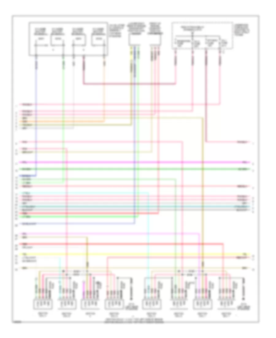 https://portal-diagnostov.com/license.html
Automotive Electricians Portal FZCO
Automotive Electricians Portal FZCO
https://portal-diagnostov.com/license.html
https://portal-diagnostov.com/license.html
Automotive Electricians Portal FZCO
Automotive Electricians Portal FZCOList of elements for 5.3L VIN C, Engine Performance Wiring Diagram (2 of 5) for Pontiac Grand Prix GT 2006:
- (front of engine) camshaft position (cmp) sensor
- (ignition coils 1, 3, 5 & 7 top left side of engine (ignition coils 2, 4, 6 & 8 top right side of engine)
- (lower right rear of engine) crankshaft position (ckp) sensor
- (top rear of engine)
- Ctrl
- Cylinder shutoff solenoid 1
- Cylinder shutoff solenoid 2
- Cylinder shutoff solenoid 3
- Cylinder shutoff solenoid 4
- Emissions2 fuse 15a
- Etc/ecm fuse 15a
- From p/train relay (diagram 4 of 5)
- G112 (left rear of engine)
- Gnd
- Ign
- Ignition
- Ignition coil 1
- Ignition coil 2
- Ignition coil 3
- Ignition coil 4
- Ignition coil 5
- Ignition coil 6
- Ignition coil 7
- Inj 1 fuse 20 a
- Inj 2 fuse 20a
- Low
- Nca
- Plug spark
- Pnk
- Red
- S105
- S106
- S130
- S131
- S132
- S133
- Spark plug
- Underhood fuse block (mounted to right strut tower)
- Valve lifter oil manifold assembly
5.3L VIN C, Engine Performance Wiring Diagram (3 of 5) for Pontiac Grand Prix GT 2006
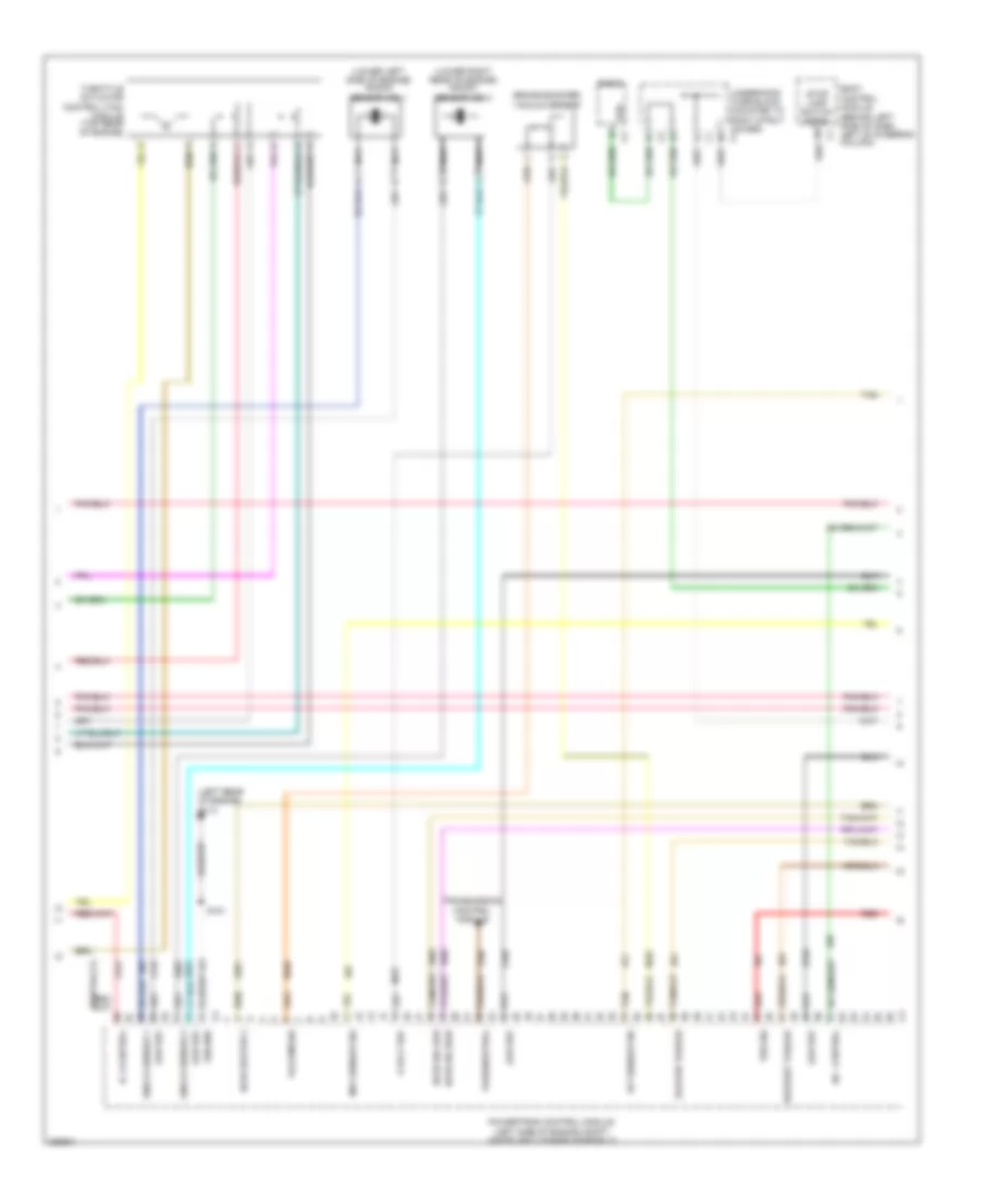 https://portal-diagnostov.com/license.html
Automotive Electricians Portal FZCO
Automotive Electricians Portal FZCO
https://portal-diagnostov.com/license.html
https://portal-diagnostov.com/license.html
Automotive Electricians Portal FZCO
Automotive Electricians Portal FZCOList of elements for 5.3L VIN C, Engine Performance Wiring Diagram (3 of 5) for Pontiac Grand Prix GT 2006:
- (behind left side of dash, left of steering column)
- (left rear of engine) g113
- (left side of engine compt, inside air cleaner assembly)
- (lower left side of engine) knock sensor (ks) 1
- (lower right rear of engine) knock sensor (ks) 2
- 5 volt ref
- A/c control
- Body control module
- Brake booster vacuum sensor
- Deliver torque
- Ground
- Ho2s heater 2
- Ho2s sig high
- Ho2s sig low
- Iat sensor sig
- Ic 2 control
- Knock sensor 1
- Knock sensor 2
- Low ref
- Maf sensor sig
- Nca
- Park/neutral
- Powertrain control module
- Radio
- Red
- Request torque
- S101
- Stop lamp switch signal
- Tan
- Throttle actuator control (tac) module (top rear of engine)
- Transmission control module
- Underhood fuse block (mounted to right strut tower) c4
- Vacuum sig
- Vss
- Vss sig
5.3L VIN C, Engine Performance Wiring Diagram (4 of 5) for Pontiac Grand Prix GT 2006
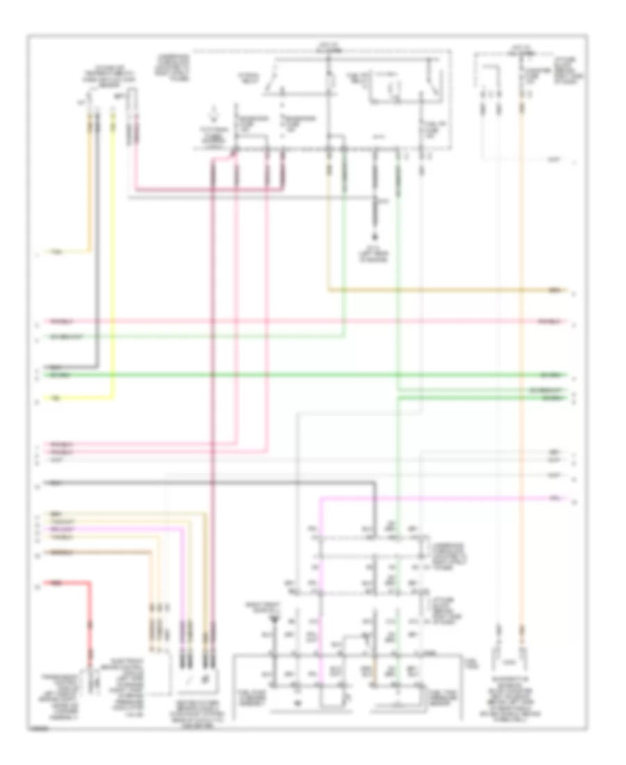 https://portal-diagnostov.com/license.html
Automotive Electricians Portal FZCO
Automotive Electricians Portal FZCO
https://portal-diagnostov.com/license.html
https://portal-diagnostov.com/license.html
Automotive Electricians Portal FZCO
Automotive Electricians Portal FZCOList of elements for 5.3L VIN C, Engine Performance Wiring Diagram (4 of 5) for Pontiac Grand Prix GT 2006:
- (right front door sill)
- A12
- Assembly)
- B12
- C1 h1
- C12
- Canister fuse 10a
- D1 c1
- D12 c2
- Electronic brake control module (left side of engine compt, part of brake pressure modulator
- Emissions1 fuse 15a
- Emissions2 fuse 15a
- Evaporative emission (evap) canister vent solenoid (behind left side of rear fascia splash shield, behind wheelwell)
- F c405
- Fuel pp fuse 15a
- Fuel pp relay
- Fuel pump & sender assembly
- Fuel tank
- Fuel tank pressure sensor
- G113 (left rear of engine)
- G302
- H6 c4
- Heated oxygen sensor (ho2s) 2 (in exhaust system, rear of catalytic converter)
- Hot at all times
- I/p fuse block (behind right side of dash)
- Iat
- Intake air temperature(iat)/ mass air flow (maf) sensor
- Maf
- Nca
- P/train relay
- Red
- Tan
- To p/train fuses (diagram 2 of 5)
- Transmission control module left side of engine compt, inside air cleaner
- Underhood fuse block (mounted to right strut tower)
- Valve)
- Vehicle sig
5.3L VIN C, Engine Performance Wiring Diagram (5 of 5) for Pontiac Grand Prix GT 2006
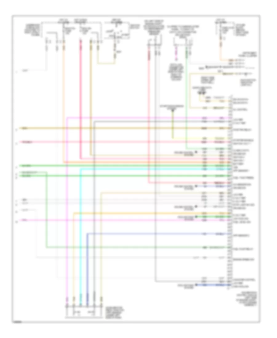 https://portal-diagnostov.com/license.html
Automotive Electricians Portal FZCO
Automotive Electricians Portal FZCO
https://portal-diagnostov.com/license.html
https://portal-diagnostov.com/license.html
Automotive Electricians Portal FZCO
Automotive Electricians Portal FZCOList of elements for 5.3L VIN C, Engine Performance Wiring Diagram (5 of 5) for Pontiac Grand Prix GT 2006:
- (clipped to knee-bolster panel, to right of data link connector)
- (on left side of engine compt, on accumulator) a/c refrigerant pressure sensor
- (right side upper left footwell)
- 5 volt ref
- A/c sensor sig
- Acc
- Accelerator pedal position (app) sensor (under left side of dash)
- App sensor 1
- App sensor 2
- Battery
- Canister control
- Class 2 data
- Computer data lines system
- Cooling fans system
- Cruise control system
- Cruise sig
- Data link connector (under left side of dash, right of steering column)
- Displays fuse 10a
- Ecm ign fuse 10a
- Ecm/tcm fuse 15a
- Engine speed sig
- Fuel level sig
- Fuel pump relay
- Fuel tank press
- G202
- Gmlan data -
- Gmlan data+
- High cooling
- Hot at all times
- Hot at hot at all times all times
- Hot in run or start
- I/p fuse block (behind right side of dash)
- Ignition 1
- Ignition 3
- Ignition switch
- Ignition volt 1
- Instrument panel cluster
- Lock
- Low cooling
- Low ref
- Malfunction indicator lamp (mil)
- Mil control
- Pnk
- Powertrain control module (left side of engine compt, in air cleaner assembly)
- Pwr/trn relay
- Run
- S201
- S211
- Splice pack sp205
- Start
- Starter enable
- Starting/charging system
- Stop lamp sw sig
- Tan
- Underhood fuse block (mounted to right strut tower)
- Vss
EXTERIOR LIGHTS
Back-up Lamps Wiring Diagram for Pontiac Grand Prix GT 2006
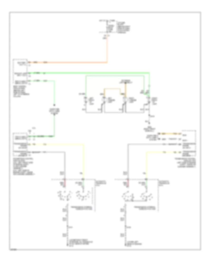 https://portal-diagnostov.com/license.html
Automotive Electricians Portal FZCO
Automotive Electricians Portal FZCO
https://portal-diagnostov.com/license.html
https://portal-diagnostov.com/license.html
Automotive Electricians Portal FZCO
Automotive Electricians Portal FZCOList of elements for Back-up Lamps Wiring Diagram for Pontiac Grand Prix GT 2006:
- (lower left rear of engine) g115
- (lower right front of engine, on transaxle stud, near starter) g113
- 3.8l
- 5.3l
- Automatic transaxle (3.8l)
- Automatic transaxle (5.3l)
- Backup lamp sply volt
- Battery volt (+)
- Bcm class 2 serial data
- Body control module (bcm) (behind left side of dash, left of steering column)
- Bus +
- Bus -
- Chmsl/ bkup fuse 15a
- Computer data lines system
- Exterior lights circuit
- G302 (right front door sill)
- Hot at all times
- I/p fuse block (behind right side of dash, in glove box opening)
- Left back- up lamp
- Left license lamp
- Pcm class 2 serial data
- Powertrain control module (pcm) (3.8l: left front side of engine compt, in air cleaner assembly) (5.3l: left side of engine compt, inside air cleaner assembly)
- Right back- up lamp
- Right license lamp
- S101
- S125
- S416
- Tan
- Transmission control module (tcm) (left side of engine compt, inside air cleaner assembly)
- Transmission internal mode switch (ims)
- Transmission range sw sig a
- Transmission range sw sig b
Exterior Lamps Wiring Diagram for Pontiac Grand Prix GT 2006
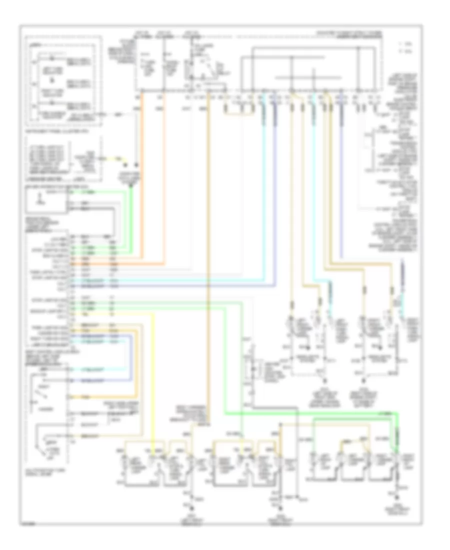 https://portal-diagnostov.com/license.html
Automotive Electricians Portal FZCO
Automotive Electricians Portal FZCO
https://portal-diagnostov.com/license.html
https://portal-diagnostov.com/license.html
Automotive Electricians Portal FZCO
Automotive Electricians Portal FZCOList of elements for Exterior Lamps Wiring Diagram for Pontiac Grand Prix GT 2006:
- (body harness, approximately 78.5 cm from breakout to c405) s407
- (left side of engine compt, part of brake pressure modulator valve) electronic brake control module (ebcm)
- (mounted to right strut tower) underhood fuse block
- (right side upper left footwell) g202
- 10 volt ref
- 3.8l
- 5.3l
- Abs
- Auto
- Backup lamp sply
- Bcm class 2
- Bcm class 2 serial data
- Body control module (bcm) (behind left side of dash, left of steering column)
- Brake pedal position sensor (under left side of dash)
- C1 c2
- C1 e2
- C1 f2
- C2 e11
- C2 f9
- C3 a9
- Center high mounted stop lamp (chmsl)
- Chmsl/ bkup fuse 15a
- Computer data lines system
- Driver information center (dic)
- G100 (right side of engine compt, at base of battery)
- G101 (left side of front end upper tie bar, near headlamp)
- G301 (left front door sill)
- G302 (right front door sill)
- Hazard
- Hazard sw sig
- Head
- Headlights system
- Hot at all times
- I/p fuse block (behind right side of dash, in glove box opening)
- Instrument panel cluster (ipc)
- Ipc class 2 serial data
- Lamp sw sig
- Left
- Left back- up lamp
- Left front marker lamp
- Left front park/ turn signal lamp
- Left license lamp
- Left rear marker lamp
- Left tail lamp
- Left tail/ stop & turn signal lamp
- Left turn indicator
- Left turn sw sig
- Lf turn lamp out lr turn lamp out rf turn lamp out rr turn lamp out turn signal on park lamps on service park lmps
- Logic
- Low ref
- Message center
- Multifunction turn signal lever
- Nca
- Off
- Park
- Park lamp sw sig
- Park lmp rly ctrl
- Pk lamps fuse 10a
- Pk lp relay
- Powertrain control module (pcm) (3.8l: left front side of engine compt, in air cleaner assembly) (5.3l: left side of engine compt, inside air cleaner assembly)
- Right
- Right back- up lamp
- Right front marker lamp
- Right front park/ turn signal lamp
- Right license lamp
- Right rear marker lamp
- Right tail lamp
- Right tail/ stop & turn signal lamp
- Right turn indicator
- Right turn sw sig
- S111
- S112
- S126
- S127
- S215
- S303
- S406
- S416
- Stop
- Stop lamp sw sig
- Tan
- Throttle actuator control (tac) module (on throttle body)
- Transmission control module (tcm) (left side of engine compt, inside air cleaner assembly)
- Trip computer class 2 serial data
- Turn audible indicator
- Turn/ haz fuse 20a
- Volt
- Volt (+)
GROUND DISTRIBUTION
Ground Distribution Wiring Diagram (1 of 3) for Pontiac Grand Prix GT 2006
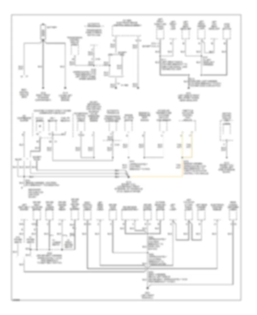 https://portal-diagnostov.com/license.html
Automotive Electricians Portal FZCO
Automotive Electricians Portal FZCO
https://portal-diagnostov.com/license.html
https://portal-diagnostov.com/license.html
Automotive Electricians Portal FZCO
Automotive Electricians Portal FZCOList of elements for Ground Distribution Wiring Diagram (1 of 3) for Pontiac Grand Prix GT 2006:
- (5.3l)
- (approximately 5 cm from breakout to pcm)
- (mounted to right strut tower) underhood fuse block
- (sulev) secondary air injection (air) control solenoid valve/ pressure sensor bank 2
- (w/ abs) electronic brake control module (ebcm)
- 3 cm from breakout to g101, toward hood ajar switch)
- 5 cm from breakout to park/turn signal lamp, toward fog lamp)
- 5.3l
- A c2
- A/c clu diode
- A/c compressor clutch
- Automatic transaxle
- B b
- Battery
- Body control module (bcm)
- C100
- Driver back heated seat element
- Driver door lock
- Driver door lock switch
- Driver heated seat relay
- Driver seat adjuster switch
- Driver seat lumbar switch
- Driver window switch
- E c1
- Electronic compass module
- Engine oil level switch
- Engine oil pressure (eop) switch
- Except 5.3l
- Except sulev
- From breakout to g301)
- Fuel pp relay 41
- G (except 5.3l)
- G101 (left side of front end upper tie bar, near headlamp)
- G102 (right front of engine compartment)
- G112 (except 5.3l) (lower left side of engine block)
- G113 (except 5.3l) (lower right front of engine, on transaxle stud, near starter)
- G113 breakout, towards pcm)
- G115 (lower left rear of engine)
- G301 (left front door sill)
- Harness)
- Hood ajar switch
- Ign 1 relay 37
- Ignition control module (icm)
- Intake air temperature (iat)/mass air flow (maf) sensor
- Left front fog lamp
- Left front marker lamp
- Left front park/turn signal lamp
- Left high beam headlamp
- Left low beam headlamp
- Left rear door lock
- Left rear marker lamp
- Left seat belt switch
- Left tail lamp
- Left tail/stop & turn signal lamp
- Logic
- Nca
- Outside rearview mirror switch
- Powertrain control module (pcm)
- Rear window defogger grid
- S101
- S102 (engine harness, approximately 5 cm from breakout to throttle actuator control (tac) module)
- S125 (approximately 5 cm from breakout to left front wheel speed sensor)
- S305 (approximately 8.5 cm from breakout to window motor)
- S330 (driver seat harness, approximately 4.5 cm from breakout to seat belt switch)
- Secondary air injection (air) pump (sulev)
- Sulev
- Switch)
- Throttle actuator control (tac) module
- Transmission control module (tcm)
- Transmission internal mode switch (ims)
- Transmission mode internal switch (ims)
- W/ abs
- W/ front heated seats
- W/ lumbar seats
- W/ power seats
- W/o power seats
Ground Distribution Wiring Diagram (2 of 3) for Pontiac Grand Prix GT 2006
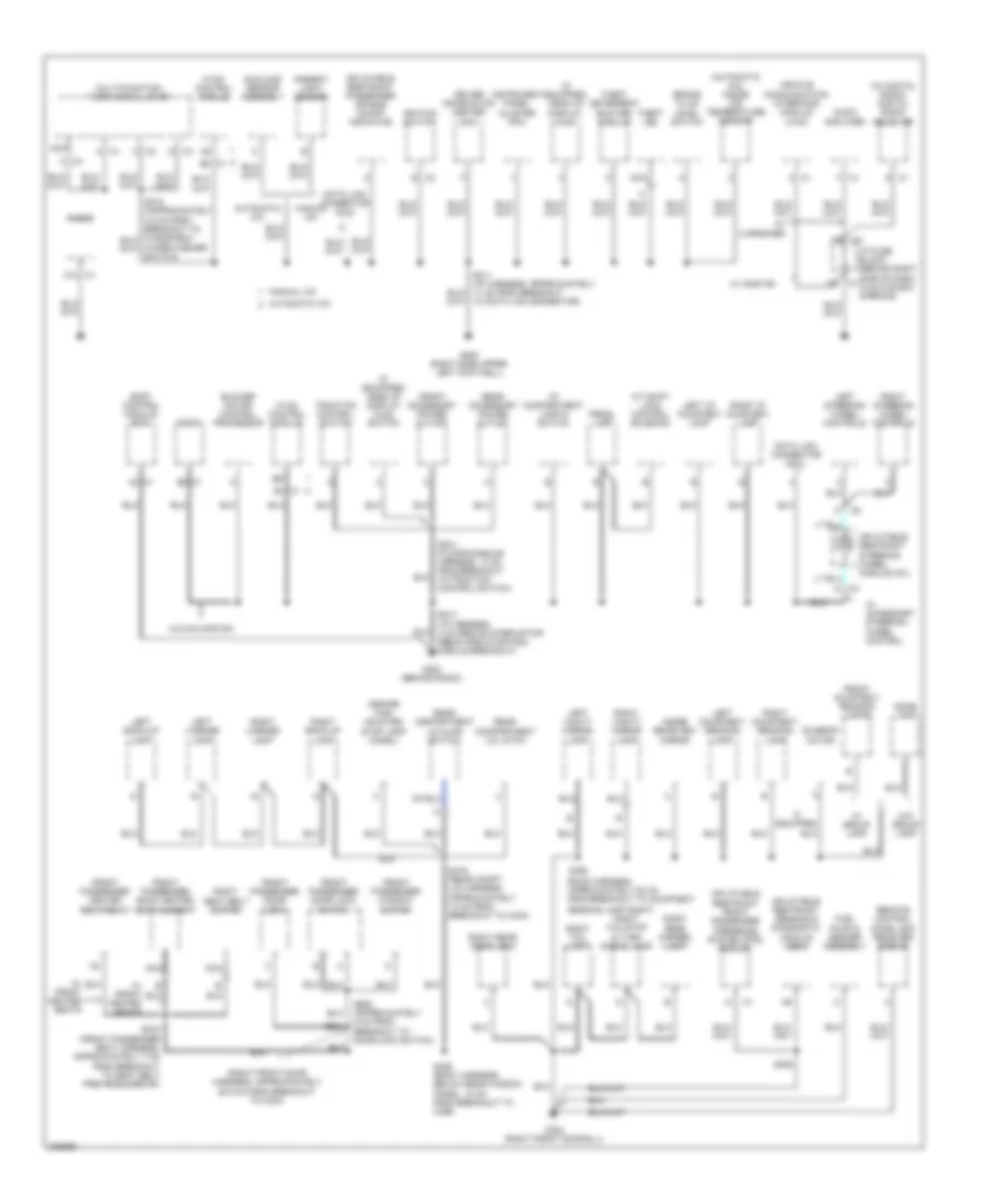 https://portal-diagnostov.com/license.html
Automotive Electricians Portal FZCO
Automotive Electricians Portal FZCO
https://portal-diagnostov.com/license.html
https://portal-diagnostov.com/license.html
Automotive Electricians Portal FZCO
Automotive Electricians Portal FZCOList of elements for Ground Distribution Wiring Diagram (2 of 3) for Pontiac Grand Prix GT 2006:
- (automatic a/c) inside air temperature sensor
- (i/p harness, 4 cm from blower motor resistors & control module breakout)
- (if equipped) head up display (hud)
- (if equipped) head up display (hud) switch
- (right front door harness, approximately 25.5 cm from breakout to c304)
- (roof harness, approximately 20 cm from breakout to courtesy/
- (w/ digital radio) digital radio receiver
- A c1
- A/t shift lock control solenoid
- A12 c1
- A6 c1
- Ambient light sensor
- Audio amplifier
- Automatic a/c
- B8 c1
- Blower motor control processor
- Body control module (bcm)
- Brake fluid level switch
- C1 b5
- Center high mounted stop lamp (chmsl)
- D c3
- Data link connector (dcl)
- Data link connector (dlc)
- Dome lamp
- Driver information center (dic)
- E c2
- F c1
- Front accessory power outlet
- Front courtesy/ reading lamps
- Front passenger back heated seat element
- Front passenger door lock
- Front passenger door lock switch
- Front passenger heated seat relay
- Front passenger window switch
- Fuel pump & sender assembly
- G200 (behind radio)
- G202 (right side upper left footwell)
- G302 (right front door sill)
- Hvac control module
- I/p compartment lamp & switch
- I/p fuse block (behind right side of dash, in glove box opening)
- If equipped
- Ignition switch
- Inflatable restraint front passenger presence system (pps) module
- Inflatable restraint passenger air bag on/off indicator
- Inflatable restraint sensing & diagnostic module (sdm)
- Inflatable restraint steering wheel module coil
- Inside rearview mirror
- Instrument panel cluster (ipc)
- K c2
- Left back-up lamp
- Left courtesy/ reading lamp
- Left i/p courtesy lamp
- Left license lamp
- Left steering wheel controls
- Left vanity mirror lamp
- Manual a/c
- Multi-function turn signal lever
- Nca
- Prndl lamp
- Radio
- Reading lamp right)
- Rear accessory power outlet
- Rear compartment lid ajar switch
- Rear compartment lid latch
- Remote control door lock receiver (rcdlr)
- Right back-up lamp
- Right courtesy/ reading lamp
- Right i/p courtesy lamp
- Right license lamp
- Right rear door lock
- Right rear marker lamp
- Right seat belt switch
- Right steering wheel controls
- Right tail lamp
- Right tail/stop & turn signal lamp
- Right vanity mirror lamp
- S211 (i/p harness, approximately 11 cm from breakout to data link connector)
- S213
- S231 (floor console harness, 13 cm from breakout to traction control switch)
- S306
- S333 (front passenger seat harness, approximately 7 cm from breakout to seat belt pretensioner rf)
- S390
- S406 (body harness, below rear window panel, 10 cm from breakout to c356)
- S416 (rear compt lid harness, approximately 13 cm from breakout to c404)
- S604
- S605 (approximately 5 cm from breakout to door lock switch)
- Sunload sensor assembly
- Sunroof motor
- Theft deterrent exciter module
- Theft led
- Traction control switch
- Vehicle communication interface module (vcim)
- W/ 8 speaker
- W/ accessory steering wheel control
- W/ front heated seats
- W/ group lamp
- W/ onstar
- W/o group lamp
- W/o navigation
- Wiper/washer switch)
Ground Distribution Wiring Diagram (3 of 3) for Pontiac Grand Prix GT 2006
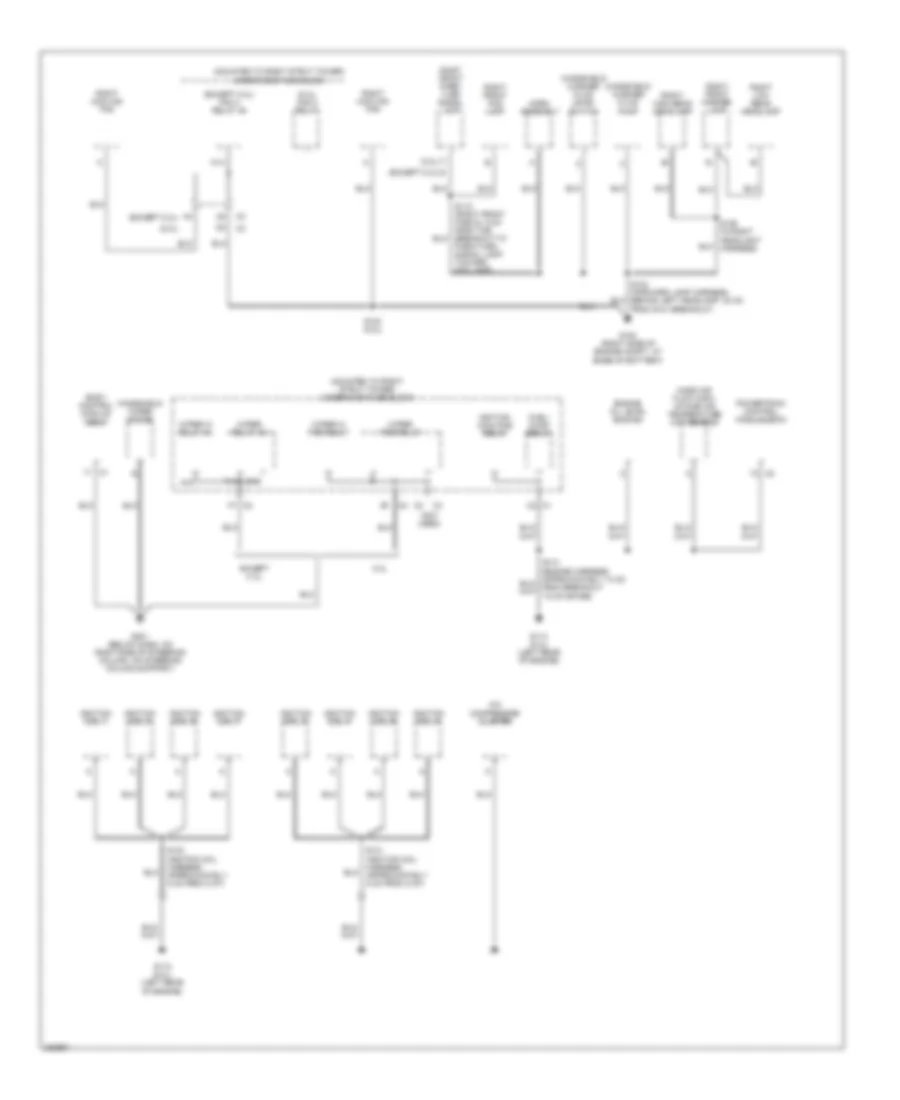 https://portal-diagnostov.com/license.html
Automotive Electricians Portal FZCO
Automotive Electricians Portal FZCO
https://portal-diagnostov.com/license.html
https://portal-diagnostov.com/license.html
Automotive Electricians Portal FZCO
Automotive Electricians Portal FZCOList of elements for Ground Distribution Wiring Diagram (3 of 3) for Pontiac Grand Prix GT 2006:
- (5.3l)
- (5.3l) fan 2 relay
- (except 5.3l)
- (except 5.3l) fan 2 relay 46
- (mounted to right strut tower) underhood fuse block
- (not used)
- 5.3l
- A/c compressor cluster
- A15
- B b
- B1 c2
- Body control module (bcm)
- C2 c1
- E15
- Engine oil level switch
- Except 5.3l
- F14
- F7 c2
- Fuel/ pump relay
- G (except 5.3l)
- G100 (right side of engine compt, at base of battery)
- G112 (5.3l) (left rear of engine)
- G113 (5.3l) (left rear of engine)
- G201 (below dash, on right side of steering column, on steering column support)
- Horn assembly
- Ignition coil 1
- Ignition coil 2
- Ignition coil 3
- Ignition coil 4
- Ignition coil 5
- Ignition coil 6
- Ignition coil 7
- Ignition coil 8
- Ignition main pcb relay
- K14
- Mass air flow (maf)/ intake air temperature (iat) sensor
- Powertrain control module (pcm)
- Right cooling fan
- Right front fog lamp
- Right front marker lamp
- Right front park/ turn signal lamp
- Right high beam headlamp
- Right low beam headlamp
- S112 (right front fascia, 5 cm from the breakout to park/turn signal lamp, toward fog lamp)
- S123 (5.3l)
- S124 (forward lamp harness, behind left headlamp, 30 cm from g101 breakout)
- S126 (in right headlight harness)
- S130 (ignition coil harness, approximately 5 cm from c107)
- S131 (ignition coil harness, approximately 5 cm from c107)
- Windshield washer fluid level switch
- Windshield washer fluid pump
- Windshield wiper motor
- Wiper hi pcb relay
- Wiper hi relay 44
- Wiper pcb relay
- Wiper relay 45
HEADLIGHTS
3.8L VIN 2
3.8L VIN 2, Headlights Wiring Diagram for Pontiac Grand Prix GT 2006
 https://portal-diagnostov.com/license.html
Automotive Electricians Portal FZCO
Automotive Electricians Portal FZCO
https://portal-diagnostov.com/license.html
https://portal-diagnostov.com/license.html
Automotive Electricians Portal FZCO
Automotive Electricians Portal FZCOList of elements for 3.8L VIN 2, Headlights Wiring Diagram for Pontiac Grand Prix GT 2006:
- (early)
- (late)
- A10
- A11
- A12
- Ambient light sensor (top of dash)
- Auto
- Automatic a/c
- B(+)
- B3 c1
- Bcm class 2 ser data
- Bcm class 2 serial
- Body control module (behind left side of dash, left of steering column)
- C10
- C11
- C12
- D10
- Displays fuse 10a
- Driver information center (dic)
- Drl ambient light
- E10 c2
- E19
- E20
- Exterior lamps off
- Flash to pass sw
- Fog
- Fog lamp ind
- Fog lamp relay ctrl
- Fog lp relay 36
- Fog lps fuse 7 10a
- Front fog lamp sw
- Ftp
- G100 (right side of engine compt, at base of battery)
- G101 (left side of front end upper tie bar, near headlamp)
- G113 (lower right front of engine, on transaxle stud, near starter)
- G19
- G20
- G202 (right side upper left footwell)
- Hdm module
- Head
- Headlamp dimmer sw
- Headlamp hi beam
- Headlamp low beam
- Headlamp on sig
- Headlamps suggested
- Hi beam relay
- High
- High beam ind
- Hot at all times
- I/p fuse block (behind right side of dash, in glove box opening)
- Ign
- Instrument panel cluster (ipc)
- Left front fog lamp
- Left front marker lamp
- Left high beam headlamp
- Left low beam headlamp
- Lf hi beam fuse 1 10a
- Lf lo beam fuse 3 10a
- Logic
- Low
- Manual a/c
- Message center
- Multi-function turn signal lever
- Nca
- Off
- Park
- Power distribution system
- Rf hi beam fuse 2 10a
- Rf lo beam fuse 4 10a
- Right front fog lamp
- Right front marker lamp
- Right high beam headlamp
- Right low beam headlamp
- S101
- S111
- S112
- S126
- S127
- S211
- S215
- Ser data
- Sp205 (clipped to knee-bolster panel, to right of data link connector)
- Sunload sensor assembly
- Trip computer class 2 serial data
- Underhood fuse block (mounted to right strut tower)
3.8L VIN 4
3.8L VIN 4, Headlights Wiring Diagram for Pontiac Grand Prix GT 2006
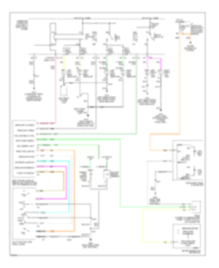 https://portal-diagnostov.com/license.html
Automotive Electricians Portal FZCO
Automotive Electricians Portal FZCO
https://portal-diagnostov.com/license.html
https://portal-diagnostov.com/license.html
Automotive Electricians Portal FZCO
Automotive Electricians Portal FZCOList of elements for 3.8L VIN 4, Headlights Wiring Diagram for Pontiac Grand Prix GT 2006:
- (early)
- (late)
- A10
- A11
- A12
- Ambient light sensor (top of dash)
- Auto
- Automatic a/c
- B(+)
- B3 c1
- Bcm class 2 ser data
- Bcm class 2 serial
- Body control module (behind left side of dash, left of steering column)
- C10
- C11
- C12
- D10
- Displays fuse 10a
- Driver information center (dic)
- Drl ambient light
- E10 c2
- E19
- E20
- Exterior lamps off
- Flash to pass sw
- Fog
- Fog lamp ind
- Fog lamp relay ctrl
- Fog lp relay 36
- Fog lps fuse 7 10a
- Front fog lamp sw
- Ftp
- G100 (right side of engine compt, at base of battery)
- G101 (left side of front end upper tie bar, near headlamp)
- G113 (lower right front of engine, on transaxle stud, near starter)
- G19
- G20
- G202 (right side upper left footwell)
- Hdm module
- Head
- Headlamp dimmer sw
- Headlamp hi beam
- Headlamp low beam
- Headlamp on sig
- Headlamps suggested
- Hi beam relay
- High
- High beam ind
- Hot at all times
- I/p fuse block (behind right side of dash, in glove box opening)
- Ign
- Instrument panel cluster (ipc)
- Left front fog lamp
- Left front marker lamp
- Left high beam headlamp
- Left low beam headlamp
- Lf hi beam fuse 1 10a
- Lf lo beam fuse 3 10a
- Logic
- Low
- Manual a/c
- Message center
- Multi-function turn signal lever
- Nca
- Off
- Park
- Power distribution system
- Rf hi beam fuse 2 10a
- Rf lo beam fuse 4 10a
- Right front fog lamp
- Right front marker lamp
- Right high beam headlamp
- Right low beam headlamp
- S101
- S111
- S112
- S126
- S127
- S211
- S215
- Ser data
- Sp205 (clipped to knee-bolster panel, to right of data link connector)
- Sunload sensor assembly
- Trip computer class 2 serial data
- Underhood fuse block (mounted to right strut tower)
5.3L VIN C
5.3L VIN C, Headlights Wiring Diagram for Pontiac Grand Prix GT 2006
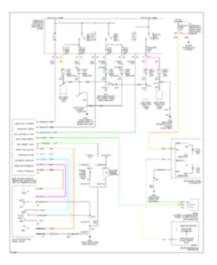 https://portal-diagnostov.com/license.html
Automotive Electricians Portal FZCO
Automotive Electricians Portal FZCO
https://portal-diagnostov.com/license.html
https://portal-diagnostov.com/license.html
Automotive Electricians Portal FZCO
Automotive Electricians Portal FZCOList of elements for 5.3L VIN C, Headlights Wiring Diagram for Pontiac Grand Prix GT 2006:
- A5 c2
- Ambient light sensor (top of dash)
- Auto
- Automatic a/c
- B(+)
- Bcm (ser data)
- Bcm class 2 serial
- Body control module (behind left side of dash, left of steering column)
- Displays fuse 10a
- Driver information center (dic)
- Drl ambient light
- Exterior lamps off
- Flash to pass sw
- Fog
- Fog lamp ind
- Fog lamp relay ctrl
- Fog lamps fuse 10a
- Fog lps pcb relay
- Front fog lamp sw
- Ftp
- G100 (right side of engine compt, at base of battery)
- G101 (left side of front end upper tie bar, near headlamp)
- G202 (right side upper left footwell)
- Gnd
- Head
- Headlamp dimmer sw
- Headlamp hi beam
- Headlamp low beam
- Headlamp on sig
- Headlamps suggested
- High
- High beam ind
- High beam pcb relay
- Hot at all times
- I/p fuse block (behind right side of dash, in glove box opening)
- Ign
- Instrument panel cluster (ipc)
- Left front fog lamp
- Left front marker lamp
- Left front park/turn signal lamp
- Left high beam headlamp
- Left low beam headlamp
- Logic
- Low
- Low beam pcb relay
- Lt hi beam fuse 10a
- Lt lo beam fuse 10a
- Manual a/c
- Message center
- Multifunction turn signal lever
- Nca
- Off
- Park
- Power distribution system
- Right front fog lamp
- Right front marker lamp
- Right front park/turn signal lamp
- Right high beam headlamp
- Right low beam headlamp
- Rt hi beam fuse 10a
- Rt lo beam fuse 10a
- S110
- S111
- S112
- S124
- S126
- S127
- S211
- S215
- Ser data
- Sp205 (clipped to knee-bolster panel, to right of data link connector)
- Sunload sensor assembly
- Trip computer class 2 serial data
- Underhood fuse block (mounted to right strut tower)
HORN
Horn Wiring Diagram for Pontiac Grand Prix GT 2006
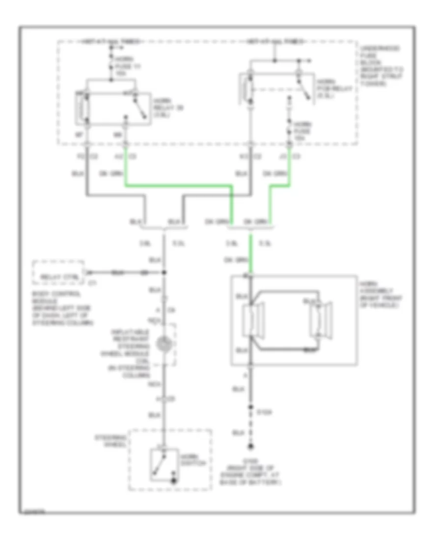 https://portal-diagnostov.com/license.html
Automotive Electricians Portal FZCO
Automotive Electricians Portal FZCO
https://portal-diagnostov.com/license.html
https://portal-diagnostov.com/license.html
Automotive Electricians Portal FZCO
Automotive Electricians Portal FZCOList of elements for Horn Wiring Diagram for Pontiac Grand Prix GT 2006:
- 3.8l
- 5.3l
- A2 c3
- Body control module (behind left side of dash, left of steering column)
- F2 c2
- G100 (right side of engine compt, at base of battery)
- Horn assembly (right front of vehicle)
- Horn fuse 11 15a
- Horn fuse 15a
- Horn pcb relay (5.3l)
- Horn relay 39 (3.8l)
- Horn switch
- Hot at all times
- Inflatable restraint steering wheel module coil (in steering column)
- J3 c3
- K3 c2
- Nca
- Relay ctrl
- S124
- Steering wheel
- Underhood fuse block (mounted to right strut tower)
INSTRUMENT CLUSTER
Instrument Cluster Wiring Diagram (1 of 2) for Pontiac Grand Prix GT 2006
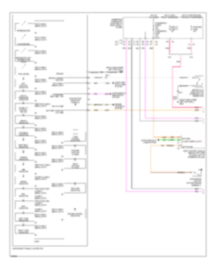 https://portal-diagnostov.com/license.html
Automotive Electricians Portal FZCO
Automotive Electricians Portal FZCO
https://portal-diagnostov.com/license.html
https://portal-diagnostov.com/license.html
Automotive Electricians Portal FZCO
Automotive Electricians Portal FZCOList of elements for Instrument Cluster Wiring Diagram (1 of 2) for Pontiac Grand Prix GT 2006:
- (right side upper left footwell) g202
- 3.8l
- 5.3l
- Abs indicator
- Abs/tcs class 2 serial data
- Air bag indicator
- Back lighting 21 leds
- Battery
- Battery positive voltage
- Bcm class 2 serial data
- Body control module (behind left side of dash, left of steering column)
- Brake fluid level switch (in brake fluid reservoir)
- Brake indicator
- Brake warning ind ctrl
- Class 2 serial data
- Compass fuse 10a
- Computer data lines system
- Cruise control indicator
- Display fuse 18 10a
- Engine controls system
- Engine coolant temperature gauge
- Fog lamp indicator
- Fuel gauge
- Ground
- High beam indicator
- Hot at all times
- Hot coolant indicator
- Hot w/ ign 1 relay energized
- Hot w/ ignition main pcb relay energized
- Ign voltage
- Instrument panel cluster (ipc)
- Ipc class 2 serial data
- Ipc/bcm class 2 serial data
- Km/h indicator
- Left turn indicator
- Logic
- Low oil pressure indicator
- Malfunction indicator lamp (mil)
- Mph indicator
- Park brake switch (on park brake assembly)
- Passenger seat belt ind
- Pcm class 2 serial data
- Pnk
- Pointer lighting 10 leds
- Right turn indicator
- S211
- Sdm class 2 serial data
- Seat belt indicator
- Speedometer
- Stability control off ind
- Switch sig
- Tachometer
- Trip computer class 2 serial data
- Turn audible indicator
- Underhood fuse block (mounted to right strut tower)
- Upshift indicator
- Washer/rvc fuse 6 15a (3.8l) washer/rvc fuse 15a (5.3l)
Instrument Cluster Wiring Diagram (2 of 2) for Pontiac Grand Prix GT 2006
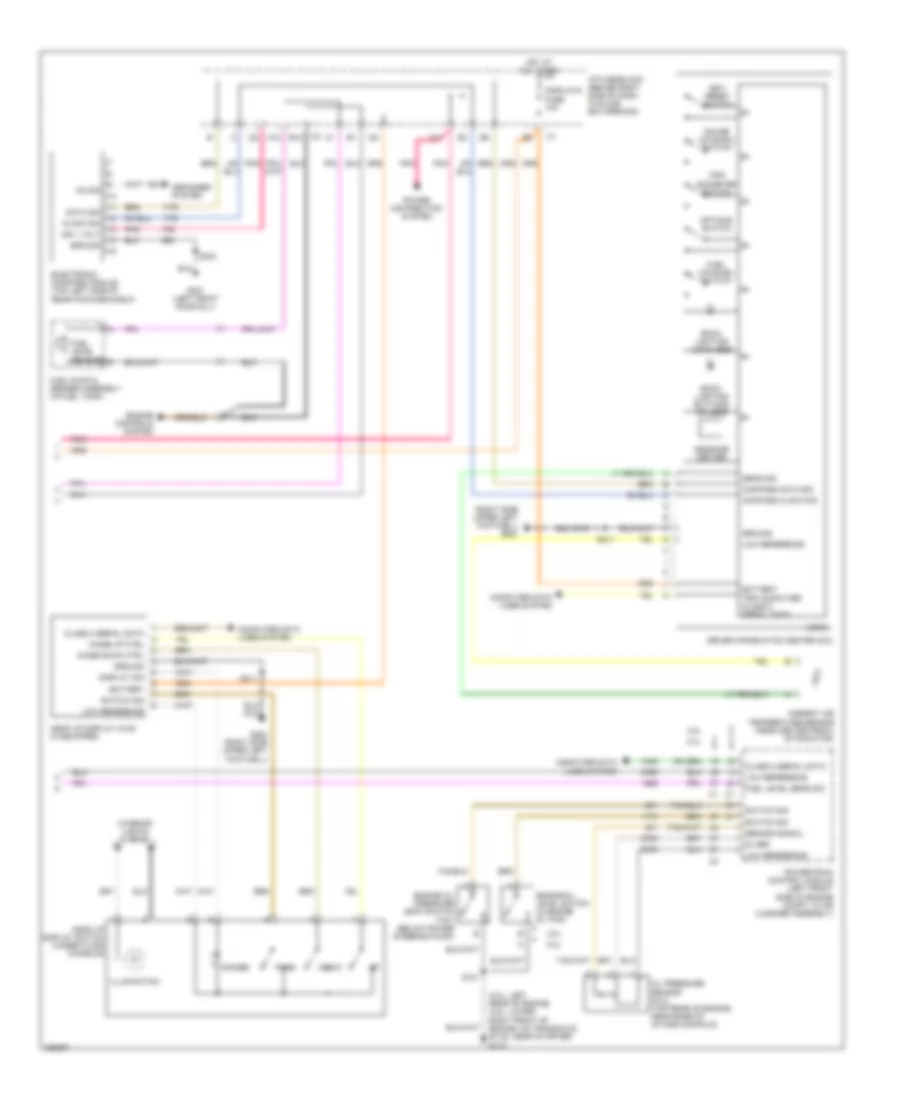 https://portal-diagnostov.com/license.html
Automotive Electricians Portal FZCO
Automotive Electricians Portal FZCO
https://portal-diagnostov.com/license.html
https://portal-diagnostov.com/license.html
Automotive Electricians Portal FZCO
Automotive Electricians Portal FZCOList of elements for Instrument Cluster Wiring Diagram (2 of 2) for Pontiac Grand Prix GT 2006:
- (5.3l: left rear of engine (3.8l: lower right front of engine, on transaxle stud, near starter) g113
- (right side upper left footwell) g202
- 3.8l
- 5.3l
- 5v ref
- A12
- Ambient air temperature sensor (near center front of radiator)
- B12
- Back lighting buttons 3-5 leds
- Back lighting lcd 9 leds
- Battery
- Class 2 serial data
- Clock sig
- Compass clock sig
- Compass data sig
- Computer data lines system
- D11
- Data sig
- Defogger system
- Dimmer
- Display sig
- Displays fuse 10a
- Down
- Driver information center (dic)
- Electronic compass module (top left side of rear package shelf)
- Engine controls system
- Engine oil level switch (in engine oil pan)
- Engine oil pressure (eop) switch (3.8l) (below power steering pump)
- Fuel (uplevel) switch
- Fuel level sens sig
- Fuel level sensor
- Fuel pump & sender assembly (in fuel tank)
- G202 (right side upper left footwell)
- G301 (left front door sill)
- Gauge (uplevel) switch
- Ground
- Head up display (hud) (if equipped)
- Head up display switch (under floor console)
- Hot at all times
- I/p fuse block (behind right side of dash, in glove box opening)
- Ign 1 volt
- Illumination
- Image down ctrl
- Image up ctrl
- Interior lights system
- Logic
- Low reference
- Message center
- Oil pressure sensor (5.3l) (top rear of engine, near base of intake manifold)
- On sig
- Options switch
- Page
- Pnk
- Power distribution system
- Powertrain control module (left front side of engine compt, in air cleaner assembly)
- S101
- S211
- S303
- Sens sig
- Sensor signal
- Set/ reset switch
- Switch sig
- Trip computer class 2 serial data
- Trip odometer switch
INTERIOR LIGHTS
Courtesy Lamps Wiring Diagram for Pontiac Grand Prix GT 2006
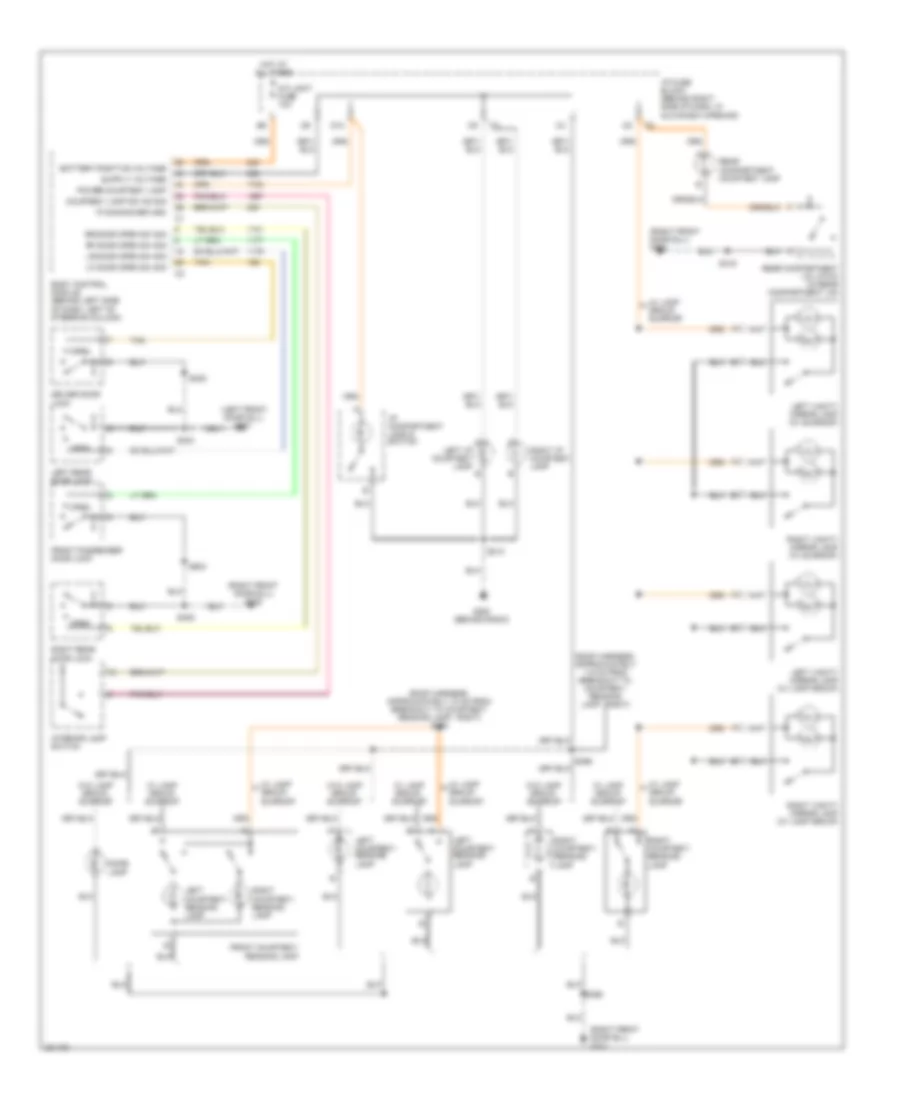 https://portal-diagnostov.com/license.html
Automotive Electricians Portal FZCO
Automotive Electricians Portal FZCO
https://portal-diagnostov.com/license.html
https://portal-diagnostov.com/license.html
Automotive Electricians Portal FZCO
Automotive Electricians Portal FZCOList of elements for Courtesy Lamps Wiring Diagram for Pontiac Grand Prix GT 2006:
- (left front door sill) g301
- (right front door sill) g302
- (roof harness, approximately 10 cm from breakout to courtesy/ reading lamp - right) s393
- (roof harness, approximately 7.5 cm from breakout to courtesy/ reading lamp - right)
- Battery positive voltage
- Body control module (behind left side of dash, left of steering column)
- Courtesy lamp sw on sig
- D10
- Dome lamp
- Driver door lock
- Front courtesy/ reading lamp
- Front passenger door lock
- G200 (behind radio)
- Hot at all times
- I/p compartment lamp & switch
- I/p fuse block (behind right side of dash, in glove box opening)
- Int light fuse 10a
- Interior lamp switch
- Ip dimming return
- Left courtesy/ reading lamp
- Left i/p courtesy lamp
- Left rear door lock
- Left vanity mirror lamp (w/ lamp group)
- Left vanity mirror lamp (w/ sunroof)
- Lf door open sw sig
- Lr door open sw sig
- Open
- Power courtesy lamp
- Rear compartment courtesy lamp
- Rear compartment lid latch (in rear compartment lid)
- Rf door open sw sig
- Right courtesy/ reading lamp
- Right i/p courtesy lamp
- Right rear door lock
- Right vanity mirror lamp (w/ lamp group)
- Right vanity mirror lamp (w/ sunroof)
- Rr door open sw sig
- S213
- S303
- S305
- S390
- S398
- S406
- S416
- S604
- Tan
- W/ lamp group, sunroof
- W/o lamp group, sunroof
Instrument Illumination Wiring Diagram for Pontiac Grand Prix GT 2006
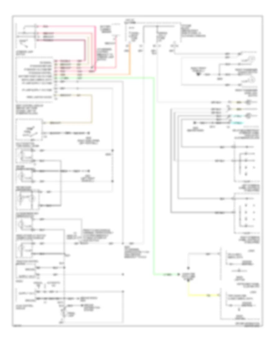 https://portal-diagnostov.com/license.html
Automotive Electricians Portal FZCO
Automotive Electricians Portal FZCO
https://portal-diagnostov.com/license.html
https://portal-diagnostov.com/license.html
Automotive Electricians Portal FZCO
Automotive Electricians Portal FZCOList of elements for Instrument Illumination Wiring Diagram for Pontiac Grand Prix GT 2006:
- (behind radio) g200
- (front floor console harness, approximately 10 cm from breakout to head up display (hud) switch) s374
- (i/p harness, 6 cm from breakout to interior lamp switch)
- (right front door sill) g302
- Auto
- Automatic a/c
- Back lighting
- Battery current sensor
- Battery positive voltage
- Bcm class 2 serial data
- Body control module (behind left side of dash, left of steering column)
- C4 f
- Chmsl/ bkup fuse 15a
- Computer data lines system
- Dimming control
- Dome
- Driver door lock switch
- Driver information center (dic)
- Driver window switch
- Front passenger door lock switch
- Front passenger window switch
- G200 (behind radio)
- G202 (right side upper left footwell)
- G301 (left front door sill)
- Ground
- Ground distribution system
- Head
- Head up display switch (under floor console)
- Hot at all times
- Hvac control module
- I/p fuse block (behind right side of dash, in glove box opening)
- Illum
- Inflatable restraint steering wheel module coil (in steering column)
- Instrument panel cluster (ipc)
- Interior lamp switch
- Ip dimming control
- Ip dimming return
- Ip dimming voltage ref
- Ipc class 2 serial data
- Left steering wheel controls (if equipped)
- Logic
- Manual a/c
- Multi-function turn signal lever
- Off
- On signal
- Outside rearview mirror switch
- Park
- Park lamp sw on sig
- Pnk
- Prndl lamp
- Radio
- Right steering wheel controls (if equipped)
- S203 (/p harness, approximately 4 cm from second breakout to dlc)
- S204
- S213
- S215
- S231
- S304
- S506
- S605
- Spring coil 2 fuse 2a
- Traction control switch
- Trip computer class 2 serial data
- W/ head up display
POWER DISTRIBUTION
3.8L VIN 2
3.8L VIN 2, Power Distribution Wiring Diagram (1 of 3) for Pontiac Grand Prix GT 2006
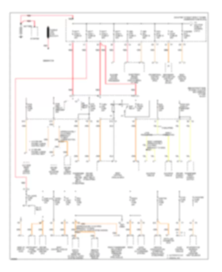 https://portal-diagnostov.com/license.html
Automotive Electricians Portal FZCO
Automotive Electricians Portal FZCO
https://portal-diagnostov.com/license.html
https://portal-diagnostov.com/license.html
Automotive Electricians Portal FZCO
Automotive Electricians Portal FZCOList of elements for 3.8L VIN 2, Power Distribution Wiring Diagram (1 of 3) for Pontiac Grand Prix GT 2006:
- (approximately 4.5 cm from breakout to seat lumbar switch) s331
- (behind right side of dash, in glove box opening) i/p fuse block
- (mounted to right strut tower) underhood fuse block
- (not used)
- Abs mtr fuse 31 40a
- Abs sol fuse 19 25a
- Air pump fuse 56 50a
- Audio amplifier (w/ 8 speaker system)
- Automatic a/c
- B1 c1
- B10
- Batt main 1 fuse 26 40a
- Batt main 2 fuse 27 50a
- Batt main 3 fuse 28 40a
- Batt main 4 fuse 30 30a
- Battery
- Blower motor control processor
- Body control module (bcm)
- C1 a1
- C1 b
- C1 e
- C2 b
- C2 d9
- C2 e2
- C2 f9
- C4 c2
- Canister fuse 10a
- Chmsl/ bkup fuse 15a
- D10
- D12 c1
- Data link connector (dlc)
- Digital radio receiver (w/ digital audio system s-band)
- Displays fuse 10a
- Dr lk/ trunk fuse 15a
- Driver heated seat relay (if equipped)
- Driver information center (dic)
- Driver seat adjuster switch
- Driver seat lumbar switch
- Driver window switch
- E12
- Early production
- Electronic brake control module (ebcm) (w/ abs)
- Evaporative emission (evap) canister vent solenoid
- F10
- Front passenger inflatable restraint pressure system (pps) module
- Generator
- Head up display (hud)
- Htd seat fuse 20a
- Hvac control module
- Hvac fuse 10a
- If equipped
- Instrument panel cluster (ipc)
- Int light fuse 10a
- Late production
- Manual a/c
- Onstar/ aldl fuse 10a
- Out side rear- view mirror switch
- Passenger front heated seat relay (if equipped)
- Passenger front window switch
- Pcm/ etc fuse 16 15a
- Pk lamps fuse 10a
- Pk lp relay
- Power lumbar control seat
- Powertrain control module (pcm)
- Pwr mirs fuse 10a
- Pwr seat circuit breaker 25a
- Pwr wdo circuit breaker 25a
- Radio
- Radio/ amp fuse 25a
- Rap relay
- Red
- Remote control door lock receiver (rcdlr)
- Rfa/ mod fuse 10a
- Rr defog relay
- Secondary air injection (air) pump relay (sulev)
- Starter
- Sun roof fuse 20a
- Sun roof module
- To aux pwr fuse 10 (diagram 2 of 3)
- Turn/ haz fuse 20a
- Vehicle communication interface module (vcim) (if equipped)
- W/ driver
- W/o driver
- Washer/ rvc fuse 6 15a
3.8L VIN 2, Power Distribution Wiring Diagram (2 of 3) for Pontiac Grand Prix GT 2006
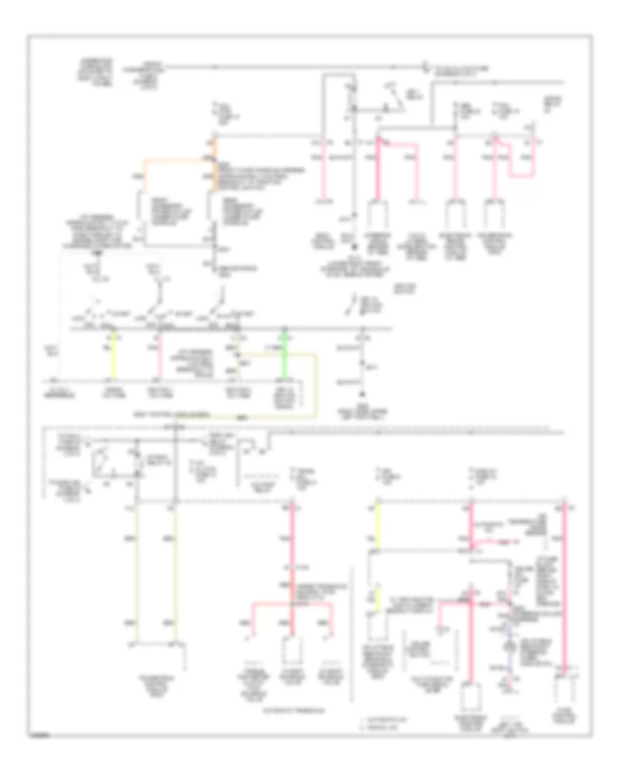 https://portal-diagnostov.com/license.html
Automotive Electricians Portal FZCO
Automotive Electricians Portal FZCO
https://portal-diagnostov.com/license.html
https://portal-diagnostov.com/license.html
Automotive Electricians Portal FZCO
Automotive Electricians Portal FZCOList of elements for 3.8L VIN 2, Power Distribution Wiring Diagram (2 of 3) for Pontiac Grand Prix GT 2006:
- (behind radio) g200
- (i/p harness, approximately 17.5 cm from breakout to pass-through to engine compt for windshield wiper motor) s200
- (i/p harness, approximately 4 cm from breakout to rcdlr)
- 1-2 shift solenoid valve
- 12 volt reference
- 2-3 shift solenoid valve
- A/c clutch fuse 13 10a
- A/c comp relay
- A10
- A11
- Abs fuse 23 10a
- Acc
- Air temperature inside sensor
- Automatic a/c
- Automatic transaxle
- Aux pwr fuse 10 25a
- Body control module
- Body control module (bcm)
- Breakout to traction control switch)
- C c2
- C1 a2
- C1 b
- C1 b3
- C1 d
- C1 d1
- C100
- C2 a12
- C2 d11
- C2 d2
- Crank relay
- Crank voltage
- Cruise control switch
- Cruise sw fuse 2a
- D11
- Display fuse 18 10a
- E c2
- E12
- Electronic brake control module (w/ abs)
- Electronic compass module
- F12
- From ign 1 relay (diagram 2 of 3)
- From washer/rvc a fuse 6 (diagram 2 of 3)
- Front accessory power outlet (under floor console)
- G113 (lower right front of engine, on transaxle stud, near starter)
- G202 (right side upper left footwell)
- Hvac control module
- I/p fuse block (behind right side of dash, in glove box opening)
- Ign 1 relay
- Ignition 1 voltage
- Ignition 3 voltage
- Ignition switch
- Inflatable restraint sensing & diagnostic module (sdm)
- Inflatable restraint steering wheel module coil
- Key in ignition switch
- Key in ignition switch signal
- Left tap shift switch (a/t)
- Lock
- Manual a/c
- Multi-function turn signal lever
- P/train relay 40
- Pcm fuse 15 10a
- Pnk
- Powertrain control module (pcm)
- Rear accessory power outlet (under floor console)
- Red
- Red (inside transaxle housing, 19 cm from c113) s115
- Run
- S101
- S201
- S211
- S231
- S240 (steering column pnk harness) c4
- Sir fuse 9 10a
- Start
- Steering angle sensor (w/ abs)
- To a/c clutch fuse (diagram 2 of 3)
- To elek ign fuse 24 (diagram 3 of 3)
- To fan 2 fuse 32 (diagram 3 of 3)
- Torque converter clutch (tcc) solenoid valve
- Trans sol fuse 21 10a
- Underhood fuse block (mounted to right strut tower)
- W/ trip monitor digital direct readout display
- Yaw & lateral acceleration sensor (w/ abs)
3.8L VIN 2, Power Distribution Wiring Diagram (3 of 3) for Pontiac Grand Prix GT 2006
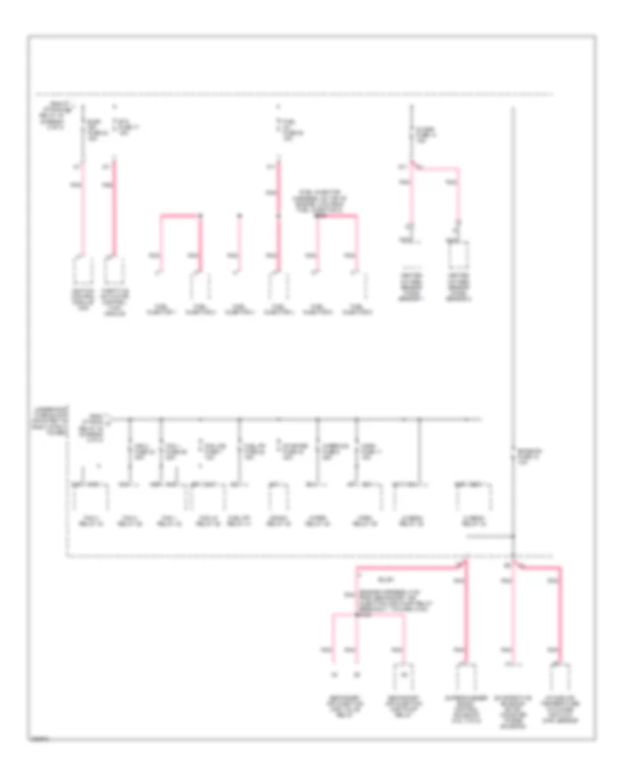 https://portal-diagnostov.com/license.html
Automotive Electricians Portal FZCO
Automotive Electricians Portal FZCO
https://portal-diagnostov.com/license.html
https://portal-diagnostov.com/license.html
Automotive Electricians Portal FZCO
Automotive Electricians Portal FZCOList of elements for 3.8L VIN 2, Power Distribution Wiring Diagram (3 of 3) for Pontiac Grand Prix GT 2006:
- (engine harness, 5 cm pnk from secondary air injection (air) pump relay breakout, toward c100) s103
- (fuel injector harness, on top of engine, 2 cm from fuel injector 2) s109
- 02 ssr fuse 14 15a
- A11
- A12
- A18
- A19
- C10
- C11
- Crank relay 48
- D11
- E14
- Elek ign fuse 24 15a
- Emission fuse 12 10a
- Etc fuse 17 15a
- Evaporative emission (evap) canister purge solenoid
- Fan 1 fuse 29 30a
- Fan 1 relay 42
- Fan 2 fuse 32 30a
- Fan 2 relay 46
- Fan 3 relay 43
- Fog lp relay 36
- Fog lps fuse 7 10a
- From p/train b relay 40 (diagram 2 of 3)
- From p/train d relay 40 (diagram 2 of 3)
- Fuel inj fuse 20 15a
- Fuel injector 1
- Fuel injector 2
- Fuel injector 3
- Fuel injector 4
- Fuel injector 5
- Fuel injector 6
- Fuel pp fuse 22 15a
- Fuel pp relay 41
- G19
- G20
- Heated oxygen sensor (ho2s) sensor 1
- Heated oxygen sensor (ho2s) sensor 2
- Hi beam relay 34
- Horn fuse 11 15a
- Horn relay 39
- Ignition control module (icm)
- Intake air temperature (iat)/mass air flow (maf) sensor
- K15
- K18
- K19
- Lo beam relay 35
- Nca
- Pnk
- Secondary air injection (air) pump relay
- Secondary air injection (air) valve relay
- Starter fuse 33 40a
- Sulev
- Supercharger boost control solenoid (3.8l (vin 4))
- Throttle actuator control (tac) module
- Underhood fuse block (mounted to right strut tower)
- Wiper relay 45
- Wiper/ws fuse 5 25a
3.8L VIN 4
3.8L VIN 4, Power Distribution Wiring Diagram (1 of 3) for Pontiac Grand Prix GT 2006
 https://portal-diagnostov.com/license.html
Automotive Electricians Portal FZCO
Automotive Electricians Portal FZCO
https://portal-diagnostov.com/license.html
https://portal-diagnostov.com/license.html
Automotive Electricians Portal FZCO
Automotive Electricians Portal FZCOList of elements for 3.8L VIN 4, Power Distribution Wiring Diagram (1 of 3) for Pontiac Grand Prix GT 2006:
- (approximately 4.5 cm from breakout to seat lumbar switch) s331
- (behind right side of dash, in glove box opening) i/p fuse block
- (mounted to right strut tower) underhood fuse block
- (not used)
- Abs mtr fuse 31 40a
- Abs sol fuse 19 25a
- Air pump fuse 56 50a
- Audio amplifier (w/ 8 speaker system)
- Automatic a/c
- B1 c1
- B10
- Batt main 1 fuse 26 40a
- Batt main 2 fuse 27 50a
- Batt main 3 fuse 28 40a
- Batt main 4 fuse 30 30a
- Battery
- Blower motor control processor
- Body control module (bcm)
- C1 a1
- C1 b
- C1 e
- C2 b
- C2 d9
- C2 e2
- C2 f9
- C4 c2
- Canister fuse 10a
- Chmsl/ bkup fuse 15a
- D10
- D12 c1
- Data link connector (dlc)
- Digital radio receiver (w/ digital audio system s-band)
- Displays fuse 10a
- Dr lk/ trunk fuse 15a
- Driver heated seat relay (if equipped)
- Driver information center (dic)
- Driver seat adjuster switch
- Driver seat lumbar switch
- Driver window switch
- E12
- Early production
- Electronic brake control module (ebcm) (w/ abs)
- Evaporative emission (evap) canister vent solenoid
- F10
- Front passenger inflatable restraint pressure system (pps) module
- Generator
- Head up display (hud)
- Htd seat fuse 20a
- Hvac control module
- Hvac fuse 10a
- If equipped
- Instrument panel cluster (ipc)
- Int light fuse 10a
- Late production
- Manual a/c
- Onstar/ aldl fuse 10a
- Out side rear- view mirror switch
- Passenger front heated seat relay (if equipped)
- Passenger front window switch
- Pcm/ etc fuse 16 15a
- Pk lamps fuse 10a
- Pk lp relay
- Power lumbar control seat
- Powertrain control module (pcm)
- Pwr mirs fuse 10a
- Pwr seat circuit breaker 25a
- Pwr wdo circuit breaker 25a
- Radio
- Radio/ amp fuse 25a
- Rap relay
- Red
- Remote control door lock receiver (rcdlr)
- Rfa/ mod fuse 10a
- Rr defog relay
- Secondary air injection (air) pump relay (sulev)
- Starter
- Sun roof fuse 20a
- Sun roof module
- To aux pwr fuse 10 (diagram 2 of 3)
- Turn/ haz fuse 20a
- Vehicle communication interface module (vcim) (if equipped)
- W/ driver
- W/o driver
- Washer/ rvc fuse 6 15a
3.8L VIN 4, Power Distribution Wiring Diagram (2 of 3) for Pontiac Grand Prix GT 2006
 https://portal-diagnostov.com/license.html
Automotive Electricians Portal FZCO
Automotive Electricians Portal FZCO
https://portal-diagnostov.com/license.html
https://portal-diagnostov.com/license.html
Automotive Electricians Portal FZCO
Automotive Electricians Portal FZCOList of elements for 3.8L VIN 4, Power Distribution Wiring Diagram (2 of 3) for Pontiac Grand Prix GT 2006:
- (behind radio) g200
- (i/p harness, approximately 17.5 cm from breakout to pass-through to engine compt for windshield wiper motor) s200
- (i/p harness, approximately 4 cm from breakout to rcdlr)
- 1-2 shift solenoid valve
- 12 volt reference
- 2-3 shift solenoid valve
- A/c clutch fuse 13 10a
- A/c comp relay
- A10
- A11
- Abs fuse 23 10a
- Acc
- Air temperature inside sensor
- Automatic a/c
- Automatic transaxle
- Aux pwr fuse 10 25a
- Body control module
- Body control module (bcm)
- Breakout to traction control switch)
- C c2
- C1 a2
- C1 b
- C1 b3
- C1 d
- C1 d1
- C100
- C2 a12
- C2 d11
- C2 d2
- Crank relay
- Crank voltage
- Cruise control switch
- Cruise sw fuse 2a
- D11
- Display fuse 18 10a
- E c2
- E12
- Electronic brake control module (w/ abs)
- Electronic compass module
- F12
- From ign 1 relay (diagram 2 of 3)
- From washer/rvc a fuse 6 (diagram 2 of 3)
- Front accessory power outlet (under floor console)
- G113 (lower right front of engine, on transaxle stud, near starter)
- G202 (right side upper left footwell)
- Hvac control module
- I/p fuse block (behind right side of dash, in glove box opening)
- Ign 1 relay
- Ignition 1 voltage
- Ignition 3 voltage
- Ignition switch
- Inflatable restraint sensing & diagnostic module (sdm)
- Inflatable restraint steering wheel module coil
- Key in ignition switch
- Key in ignition switch signal
- Left tap shift switch (a/t)
- Lock
- Manual a/c
- Multi-function turn signal lever
- P/train relay 40
- Pcm fuse 15 10a
- Pnk
- Powertrain control module (pcm)
- Rear accessory power outlet (under floor console)
- Red
- Red (inside transaxle housing, 19 cm from c113) s115
- Run
- S101
- S201
- S211
- S231
- S240 (steering column pnk harness) c4
- Sir fuse 9 10a
- Start
- Steering angle sensor (w/ abs)
- To a/c clutch fuse (diagram 2 of 3)
- To elek ign fuse 24 (diagram 3 of 3)
- To fan 2 fuse 32 (diagram 3 of 3)
- Torque converter clutch (tcc) solenoid valve
- Trans sol fuse 21 10a
- Underhood fuse block (mounted to right strut tower)
- W/ trip monitor digital direct readout display
- Yaw & lateral acceleration sensor (w/ abs)
3.8L VIN 4, Power Distribution Wiring Diagram (3 of 3) for Pontiac Grand Prix GT 2006
 https://portal-diagnostov.com/license.html
Automotive Electricians Portal FZCO
Automotive Electricians Portal FZCO
https://portal-diagnostov.com/license.html
https://portal-diagnostov.com/license.html
Automotive Electricians Portal FZCO
Automotive Electricians Portal FZCOList of elements for 3.8L VIN 4, Power Distribution Wiring Diagram (3 of 3) for Pontiac Grand Prix GT 2006:
- (engine harness, 5 cm pnk from secondary air injection (air) pump relay breakout, toward c100) s103
- (fuel injector harness, on top of engine, 2 cm from fuel injector 2) s109
- 02 ssr fuse 14 15a
- A11
- A12
- A18
- A19
- C10
- C11
- Crank relay 48
- D11
- E14
- Elek ign fuse 24 15a
- Emission fuse 12 10a
- Etc fuse 17 15a
- Evaporative emission (evap) canister purge solenoid
- Fan 1 fuse 29 30a
- Fan 1 relay 42
- Fan 2 fuse 32 30a
- Fan 2 relay 46
- Fan 3 relay 43
- Fog lp relay 36
- Fog lps fuse 7 10a
- From p/train b relay 40 (diagram 2 of 3)
- From p/train d relay 40 (diagram 2 of 3)
- Fuel inj fuse 20 15a
- Fuel injector 1
- Fuel injector 2
- Fuel injector 3
- Fuel injector 4
- Fuel injector 5
- Fuel injector 6
- Fuel pp fuse 22 15a
- Fuel pp relay 41
- G19
- G20
- Heated oxygen sensor (ho2s) sensor 1
- Heated oxygen sensor (ho2s) sensor 2
- Hi beam relay 34
- Horn fuse 11 15a
- Horn relay 39
- Ignition control module (icm)
- Intake air temperature (iat)/mass air flow (maf) sensor
- K15
- K18
- K19
- Lo beam relay 35
- Nca
- Pnk
- Secondary air injection (air) pump relay
- Secondary air injection (air) valve relay
- Starter fuse 33 40a
- Sulev
- Supercharger boost control solenoid (3.8l (vin 4))
- Throttle actuator control (tac) module
- Underhood fuse block (mounted to right strut tower)
- Wiper relay 45
- Wiper/ws fuse 5 25a
5.3L VIN C
5.3L VIN C, Power Distribution Wiring Diagram (1 of 3) for Pontiac Grand Prix GT 2006
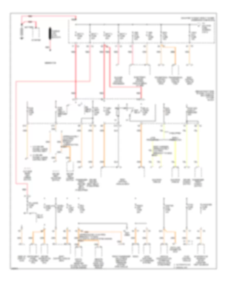 https://portal-diagnostov.com/license.html
Automotive Electricians Portal FZCO
Automotive Electricians Portal FZCO
https://portal-diagnostov.com/license.html
https://portal-diagnostov.com/license.html
Automotive Electricians Portal FZCO
Automotive Electricians Portal FZCOList of elements for 5.3L VIN C, Power Distribution Wiring Diagram (1 of 3) for Pontiac Grand Prix GT 2006:
- (behind right side of dash, in glove box opening) i/p fuse block
- (mounted to right strut tower) underhood fuse block
- (not used)
- A1 c1
- Abs mtr fuse 40a
- Abs sol fuse 25a
- Audio amplifier (w/ 8 speaker system)
- Automatic a/c
- B c1
- B c2
- B10
- Batt 1 fuse 50a
- Batt 2 fuse 50a
- Batt 3 fuse 40a
- Batt 4 fuse 30a
- Battery
- Blower motor control processor
- Body control module (bcm)
- C1 b1
- C2 g1
- C4 f1
- Canister fuse 10a
- Chmsl/ bkup fuse 15a
- D10
- D12 c1
- Data link connector (dlc)
- Digital radio receiver (w/ digital audio system s-band)
- Displays fuse 10a
- Dr lk/ trunk fuse 15a
- Driver heated seat relay (if equipped)
- Driver information center (dic)
- Driver seat adjuster switch
- Driver seat lumbar switch
- Driver window switch
- E c1
- E12
- E2 c2
- Early production
- Ecm/ tcm fuse 15a
- Electronic brake control module (ebcm) (w/ abs)
- Evaporative emission (evap) canister vent solenoid
- F10
- F9 c2
- Front passenger inflatable restraint pressure system (pps) module
- Generator
- Head up display (hud)
- Htd seat fuse 20a
- Hvac control module
- Hvac fuse 10a
- If equipped
- Instrument panel cluster (ipc)
- Int light fuse 10a
- Late production
- Manual a/c
- Onstar/ aldl fuse 10a
- Out side rear- view mirror switch
- Passenger front heated seat relay (if equipped)
- Passenger front window switch
- Pk lamps fuse 10a
- Pk lp relay
- Power lumbar control seat
- Powertrain control module (pcm)
- Pwr mirs fuse 10a
- Pwr seat circuit breaker 25a
- Pwr wdo circuit breaker 25a
- Radio
- Radio/ amp fuse 25a
- Rap relay
- Red
- Remote control door lock receiver (rcdlr)
- Rfa/ mod fuse 10a
- Rr defog relay
- Starter
- Sun roof fuse 20a
- Sun roof module
- To aux pwr fuse (diagram 2 of 3)
- Transmission control module (tcm)
- Turn/ haz fuse 20a
- Vehicle communication interface module (vcim) (if equipped)
- W/ driver
- W/o driver
- Wsw/ rvc fuse 15a
5.3L VIN C, Power Distribution Wiring Diagram (2 of 3) for Pontiac Grand Prix GT 2006
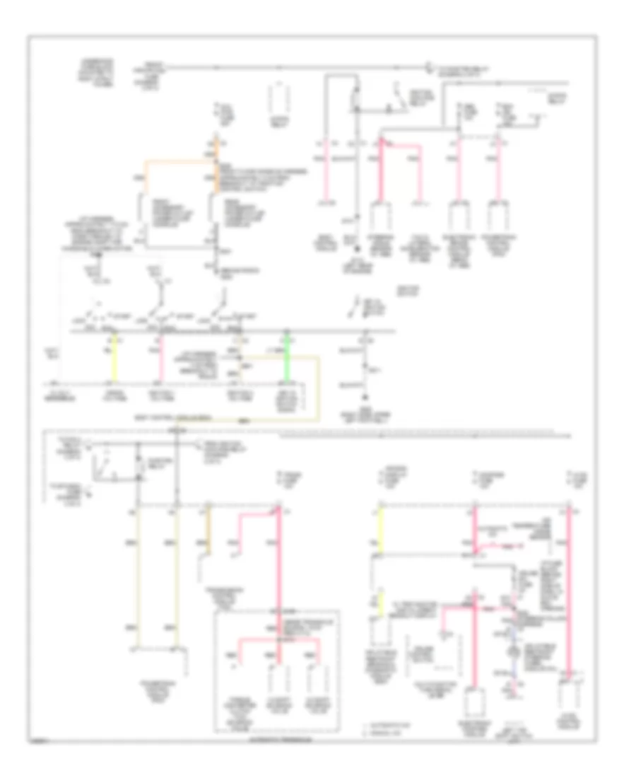 https://portal-diagnostov.com/license.html
Automotive Electricians Portal FZCO
Automotive Electricians Portal FZCO
https://portal-diagnostov.com/license.html
https://portal-diagnostov.com/license.html
Automotive Electricians Portal FZCO
Automotive Electricians Portal FZCOList of elements for 5.3L VIN C, Power Distribution Wiring Diagram (2 of 3) for Pontiac Grand Prix GT 2006:
- (behind radio) g200
- (i/p harness, approximately 17.5 cm from breakout to pass-through to engine compt for windshield wiper motor) s200
- (i/p harness, approximately 4 cm from breakout to rcdlr)
- (inside transaxle housing, 19 cm red
- 1-2 shift solenoid valve
- 12 volt reference
- 2-3 shift solenoid valve
- A10
- A2 c1
- Abs fuse 10a
- Acc
- Air bag/ display fuse 10a
- Air temperature inside sensor
- Automatic a/c
- Automatic transaxle
- Aux pwr fuse 25a
- Body control module
- Body control module (bcm)
- Breakout to traction control switch)
- C c2
- C1 b
- C1 c2
- C1 j3
- C100
- C2 d2
- C2 e
- C2 h2
- Compass fuse 10a
- Crank voltage
- Cruise control switch
- Cruise sw fuse 2a
- D c1
- D11
- E12
- Ecm ign fuse 10a
- Electronic brake control module (ebcm) (w/ abs)
- Electronic compass module
- From c113) s115
- From ignition main pcb relay (diagram 2 of 3)
- From wsw/rvc a fuse (diagram 2 of 3)
- Front accessory power outlet (under floor console)
- G113 (left rear of engine)
- G202 (right side upper left footwell)
- Hvac control module
- Hvac fuse 10a
- I/p fuse block (behind right side of dash, in glove box opening)
- Ignition 1 voltage
- Ignition 3 voltage
- Ignition main pcb relay
- Ignition switch
- Inflatable restraint sensing & diagnostic module (sdm)
- Inflatable restraint steering wheel module coil
- Key in ignition switch
- Key in ignition switch signal
- Left tap shift switch (a/t)
- Lock
- Manual a/c
- Multi-function turn signal lever
- Pnk
- Powertrain control module (pcm)
- Pwr/trn relay
- Rear accessory power outlet (under floor console)
- Red
- Run
- S101
- S201
- S211
- S231
- S240 (steering column pnk harness) c4
- Start
- Steering angle sensor (w/ abs)
- Strtr relay
- To etc/ecm fuse (diagram 3 of 3)
- To fan 2 relay (diagram 3 of 3)
- To pwr/trn relay (diagram 2 of 3)
- Torque converter clutch (tcc) solenoid valve
- Trans fuse 10a
- Transmission control module (tcm)
- Underhood fuse block (mounted to right strut tower)
- W/ trip monitor digital direct readout display
- Yaw & lateral acceleration sensor (w/ abs)
5.3L VIN C, Power Distribution Wiring Diagram (3 of 3) for Pontiac Grand Prix GT 2006
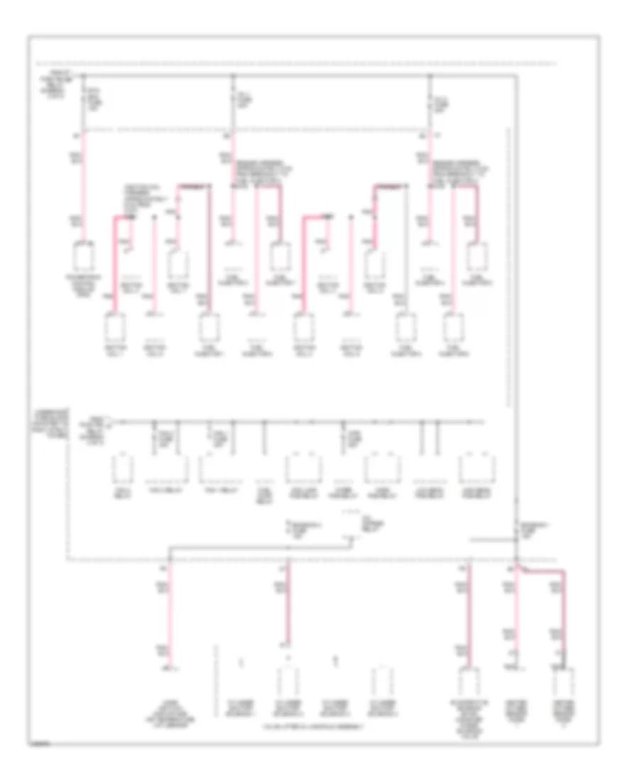 https://portal-diagnostov.com/license.html
Automotive Electricians Portal FZCO
Automotive Electricians Portal FZCO
https://portal-diagnostov.com/license.html
https://portal-diagnostov.com/license.html
Automotive Electricians Portal FZCO
Automotive Electricians Portal FZCOList of elements for 5.3L VIN C, Power Distribution Wiring Diagram (3 of 3) for Pontiac Grand Prix GT 2006:
- (ignition coil harness, approximately 6 cm from c107) s106
- A/c cmprsr relay
- Cylinder shutoff solenoid 1
- Cylinder shutoff solenoid 2
- Cylinder shutoff solenoid 3
- Cylinder shutoff solenoid 4
- Emission 1 fuse 15a
- Emission 2 fuse 15a
- Etc/ ecm fuse 15a
- Evaporative emission (evap) canister purge solenoid valve
- Fan 1 fuse 30a
- Fan 1 relay
- Fan 2 fuse 30a
- Fan 2 relay
- Fan 3 relay
- Fog lamp pcb relay
- From pwr/trn b relay (diagram 2 of 3)
- From pwr/trn d relay (diagram 2 of 3)
- Fuel injector 1
- Fuel injector 2
- Fuel injector 3
- Fuel injector 4
- Fuel injector 5
- Fuel injector 6
- Fuel injector 7
- Fuel injector 8
- Fuel pump relay
- Heated oxygen sensor (ho2s)
- High beam pcb relay
- Horn pcb relay
- Ignition coil 1
- Ignition coil 2
- Ignition coil 3
- Ignition coil 4
- Ignition coil 5
- Ignition coil 6
- Ignition coil 7
- Ignition coil 8
- Inj 1 fuse 20a
- Inj 2 fuse 20a
- Low beam pcb relay
- Mass air flow (maf)/intake air temperature (iat) sensor
- Nca
- Pnk
- Powertrain control module (pcm)
- S105
- Underhood fuse block (mounted to right strut tower)
- Valve lifter oil manifold assembly
- Wiper pcb relay
- Wpr fuse 25a
POWER DOOR LOCKS
Power Door Locks Wiring Diagram for Pontiac Grand Prix GT 2006
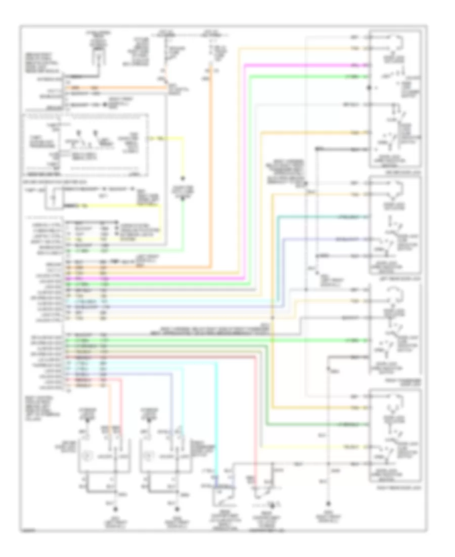 https://portal-diagnostov.com/license.html
Automotive Electricians Portal FZCO
Automotive Electricians Portal FZCO
https://portal-diagnostov.com/license.html
https://portal-diagnostov.com/license.html
Automotive Electricians Portal FZCO
Automotive Electricians Portal FZCOList of elements for Power Door Locks Wiring Diagram for Pontiac Grand Prix GT 2006:
- (behind right side of dash) remote control door lock receiver (rcdlr)
- (body harness, below right front passenger seat, approximately 26 cm from second breakout to g301) s315
- (if equipped) rear window antenna grid
- (left front door sill) g301
- (right front door sill) g302
- A5 c2
- Ajar
- Ajar ind
- Ajar sw sig
- Antenna sig
- Bcm class 2
- Bcm class 2 serial data
- Body control module (bcm) (behind left side of dash, left of steering column)
- Coax
- Computer data lines system
- Door lock actuator
- Door lock ajar indicator switch
- Door lock cylinder switch
- Door lock open indicator switch
- Dr ajar sw sig
- Dr lk/ trunk fuse 15a
- Dr open sw sig
- Driver door lock
- Driver door lock switch
- Driver information center (dic)
- Enable sig
- Front passenger door lock
- Front passenger door lock switch
- G202 (right side upper left footwell)
- G301 (left front door sill)
- G302 (right front door sill)
- Ground
- Headlights system exterior lights system
- Hi beam relay
- Horn rly ctrl
- Horns system
- Hot at all times
- I/p fuse block (behind right side of dash, in glove box opening)
- Interior lights system
- Lamp rly ctrl
- Left rear door lock
- Lid ajar sw
- Lock
- Lock ctrl
- Lock sig
- Logic
- Message center
- Nca
- Open
- Option
- Rear compartment lid ajar switch (early production)
- Rear compartment lid latch (in rear compartment lid)
- Rfa/mod fuse 10a
- Right rear door lock
- S211
- S301 (w/ digital radio)
- S303
- S304
- S305
- S314 (body harness, below right side of front passenger seat, approximately 29 cm from second breakout to c311)
- S406
- S416
- S604
- S605
- Scrty ind ctrl
- Set/ reset
- Tamper sw sig
- Tan
- Theft led
- Theft off
- Theft on
- Theft system not programmed
- Trip computer serial data class 2
- Unlock
- Unlock ctrl
- Unlock sig
- Volt (+)
POWER MIRRORS
Power Mirrors Wiring Diagram for Pontiac Grand Prix GT 2006
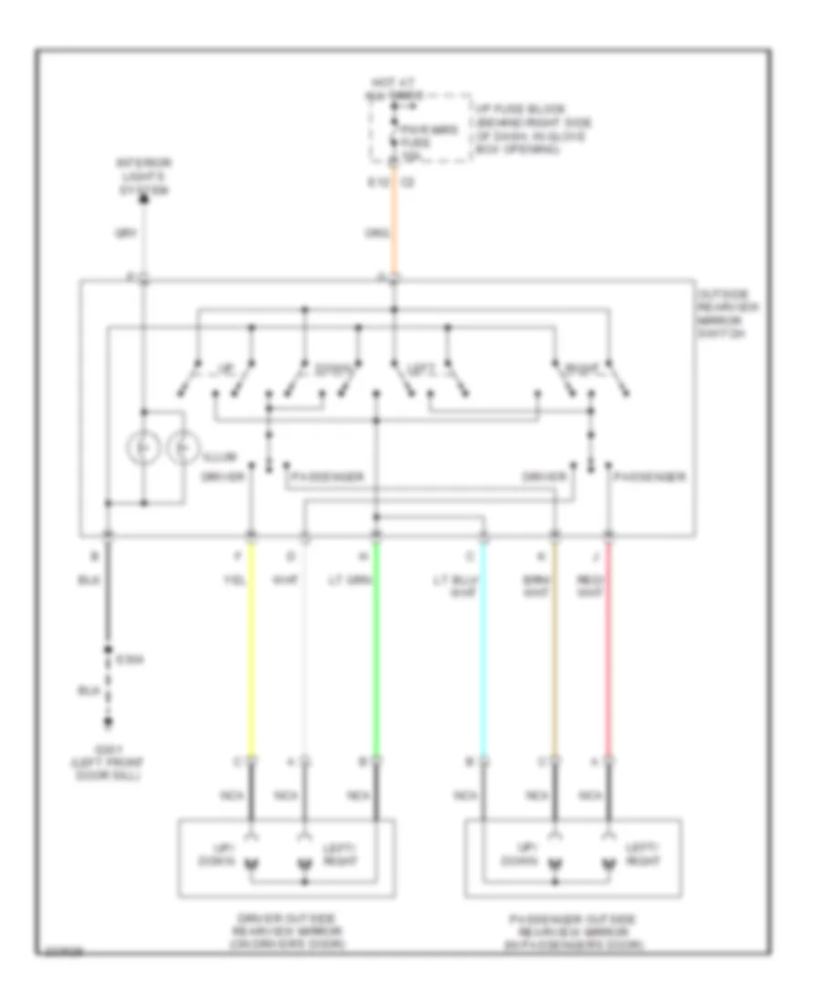 https://portal-diagnostov.com/license.html
Automotive Electricians Portal FZCO
Automotive Electricians Portal FZCO
https://portal-diagnostov.com/license.html
https://portal-diagnostov.com/license.html
Automotive Electricians Portal FZCO
Automotive Electricians Portal FZCOList of elements for Power Mirrors Wiring Diagram for Pontiac Grand Prix GT 2006:
- Down
- Driver
- Driver outside rearview mirror (on driver's door)
- E12
- G301 (left front door sill)
- Hot at all times
- I/p fuse block (behind right side of dash, in glove box opening)
- Illum
- Interior lights system
- Left
- Left/ right
- Nca
- Outside rearview mirror switch
- Passenger
- Passenger outside rearview mirror (in passenger's door)
- Pwr mirs fuse 10a
- Right
- S304
- Up/ down
POWER SEATS
Driver Power Seat Wiring Diagram for Pontiac Grand Prix GT 2006
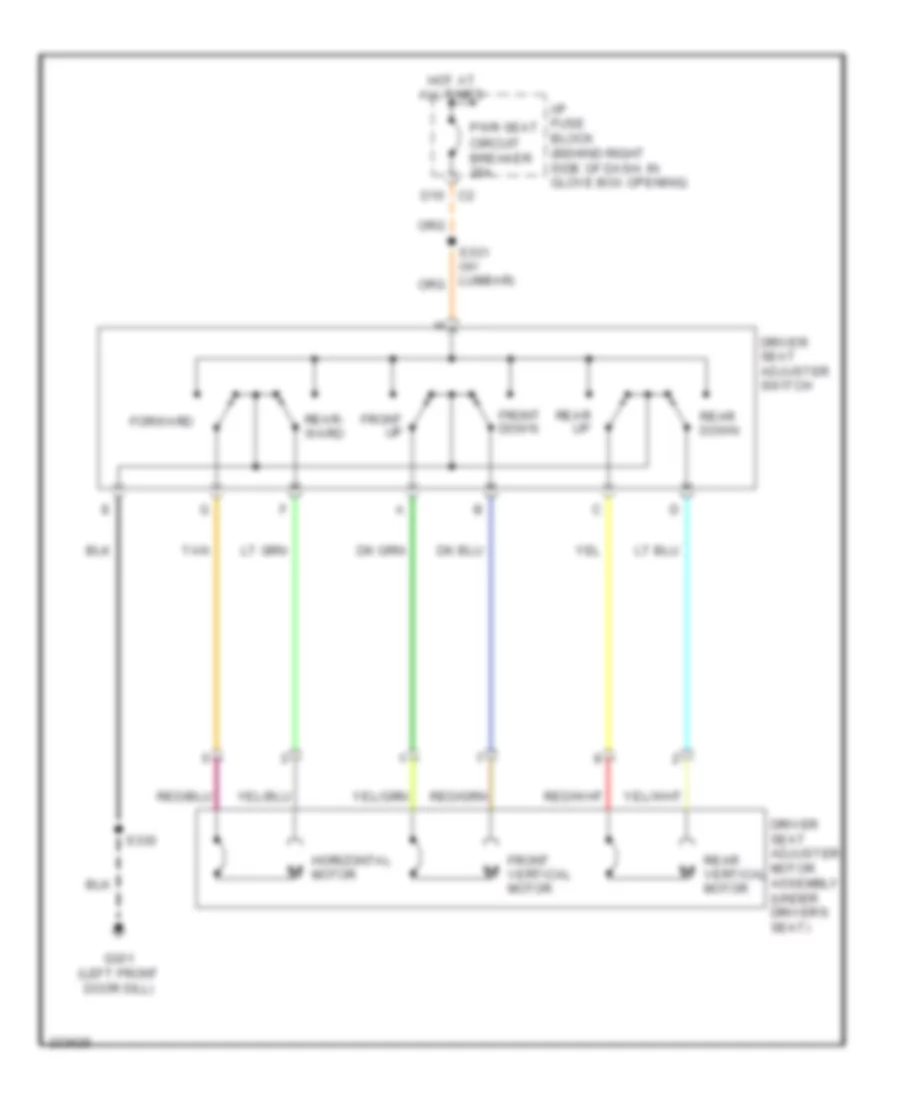 https://portal-diagnostov.com/license.html
Automotive Electricians Portal FZCO
Automotive Electricians Portal FZCO
https://portal-diagnostov.com/license.html
https://portal-diagnostov.com/license.html
Automotive Electricians Portal FZCO
Automotive Electricians Portal FZCOList of elements for Driver Power Seat Wiring Diagram for Pontiac Grand Prix GT 2006:
- D10 c2
- Driver seat adjuster motor assembly (under driver's seat)
- Driver seat adjuster switch
- Forward
- Front down
- Front up
- Front vertical motor
- G301 (left front door sill)
- Horizontal motor
- Hot at all times
- I/p fuse block (behind right side of dash, in glove box opening)
- Pwr seat circuit breaker 25a
- Rear down
- Rear up
- Rear vertical motor
- Rear- ward
- S330
- Tan
Heated Seats Wiring Diagram for Pontiac Grand Prix GT 2006
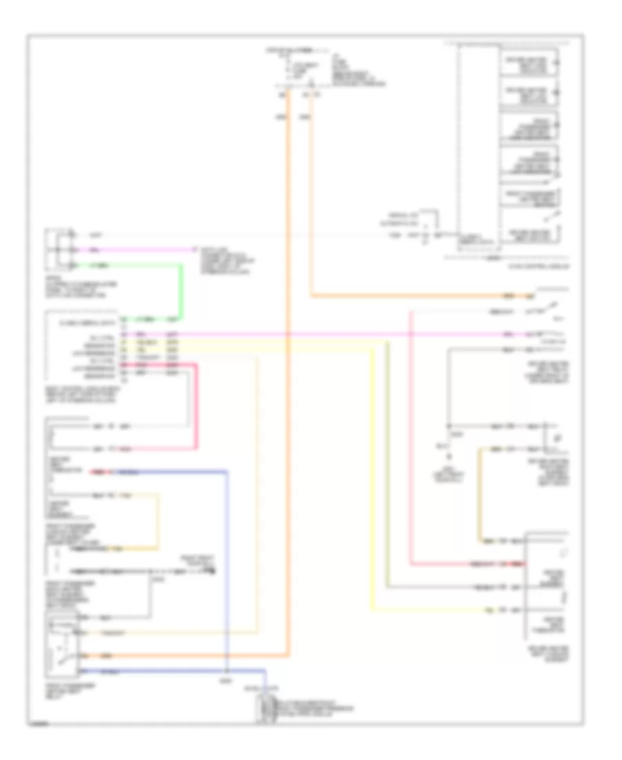 https://portal-diagnostov.com/license.html
Automotive Electricians Portal FZCO
Automotive Electricians Portal FZCO
https://portal-diagnostov.com/license.html
https://portal-diagnostov.com/license.html
Automotive Electricians Portal FZCO
Automotive Electricians Portal FZCOList of elements for Heated Seats Wiring Diagram for Pontiac Grand Prix GT 2006:
- (right front door sill) g302
- Automatic a/c
- Body control module (bcm) (behind left side of dash, left of steering column)
- C2 f9
- Class 2 serial data
- Data link connector (dlc) (under left side of dash, right of steering column)
- Driver heated back seat element (in driver's seat back)
- Driver heated seat cushion element
- Driver heated seat high indicator
- Driver heated seat low indicator
- Driver heated seat relay (under front of driver's seat)
- Driver heated seat switch
- Element
- Front passenger back heated seat element (in passenger's seat back)
- Front passenger cushion heated seat element (under seat cover)
- Front passenger heated seat high indicator
- Front passenger heated seat low indicator
- Front passenger heated seat relay
- Front passenger heated seat switch
- G301 (left front door sill)
- Heated
- Heated seat element
- Heated seat thermistor
- Hot at all times
- Htd seat fuse 20a
- Hvac control module
- I/p fuse block (behind right side of dash, in glove box opening)
- Logic
- Low reference
- Manual a/c
- Nca
- Pnk
- Red
- Rly ctrl
- S308
- S330
- S333
- Seat
- Sensor sig
- Sp205 (clipped to knee-bolster panel, to right of data link connector)
- Tan
- Thermistor
- Voltage inflatable restraint front passenger presence system (pps) module
Lumbar Wiring Diagram for Pontiac Grand Prix GT 2006
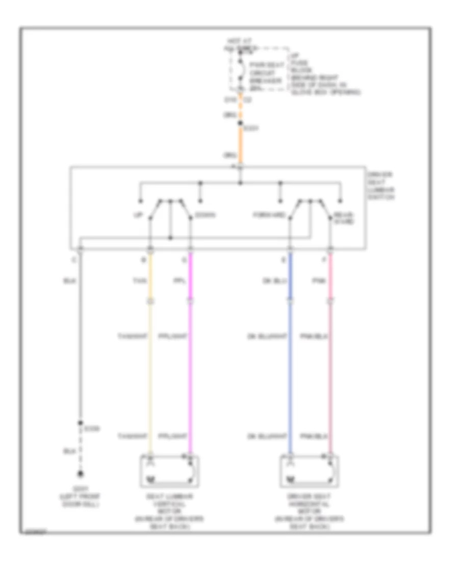 https://portal-diagnostov.com/license.html
Automotive Electricians Portal FZCO
Automotive Electricians Portal FZCO
https://portal-diagnostov.com/license.html
https://portal-diagnostov.com/license.html
Automotive Electricians Portal FZCO
Automotive Electricians Portal FZCOList of elements for Lumbar Wiring Diagram for Pontiac Grand Prix GT 2006:
- D10 c2
- Down
- Driver seat horizontal motor (in rear of driver's seat back)
- Driver seat lumbar switch
- Forward
- G301 (left front door sill)
- Hot at all times
- I/p fuse block (behind right side of dash, in glove box opening)
- Pnk
- Pwr seat circuit breaker 25a
- Rear- ward
- S330
- S331
- Seat lumbar vertical motor (in rear of driver's seat back)
- Tan
POWER TOP/SUNROOF
Power Top/Sunroof Wiring Diagram for Pontiac Grand Prix GT 2006
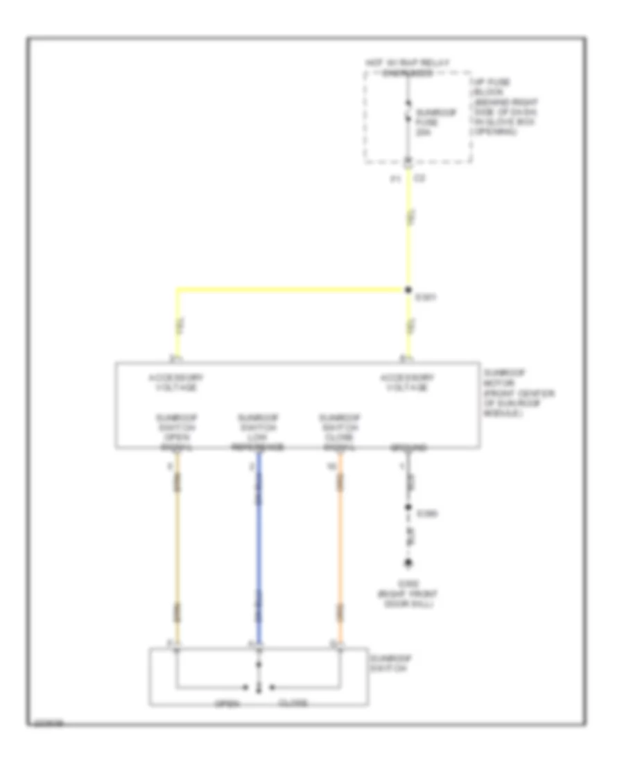 https://portal-diagnostov.com/license.html
Automotive Electricians Portal FZCO
Automotive Electricians Portal FZCO
https://portal-diagnostov.com/license.html
https://portal-diagnostov.com/license.html
Automotive Electricians Portal FZCO
Automotive Electricians Portal FZCOList of elements for Power Top/Sunroof Wiring Diagram for Pontiac Grand Prix GT 2006:
- Accessory voltage
- Close
- G302 (right front door sill)
- Ground
- Hot w/ rap relay energized
- I/p fuse block (behind right side of dash, in glove box opening)
- Open
- S301
- S390
- Sunroof fuse 20a
- Sunroof motor (front center of sun roof module)
- Sunroof switch
- Sunroof switch close signal
- Sunroof switch low reference
- Sunroof switch open signal
POWER WINDOWS
Power Windows Wiring Diagram for Pontiac Grand Prix GT 2006
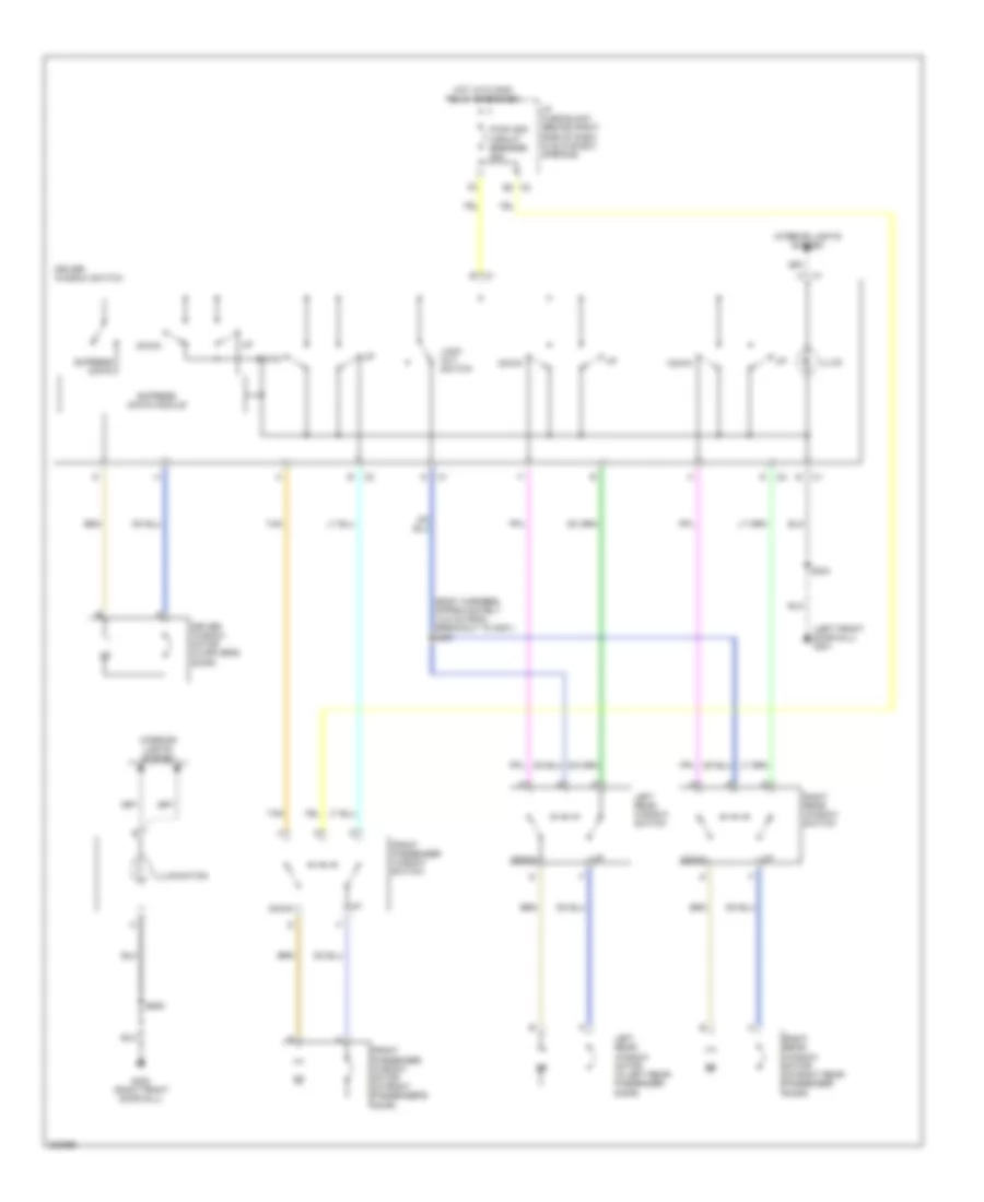 https://portal-diagnostov.com/license.html
Automotive Electricians Portal FZCO
Automotive Electricians Portal FZCO
https://portal-diagnostov.com/license.html
https://portal-diagnostov.com/license.html
Automotive Electricians Portal FZCO
Automotive Electricians Portal FZCOList of elements for Power Windows Wiring Diagram for Pontiac Grand Prix GT 2006:
- (body harness, approximately 14.5 cm from breakout to g301) s307
- (left front door sill) g301
- C1 a
- C1 b
- Down
- Driver window motor (in driver's door)
- Driver window switch
- Express down
- Express down module
- Front passenger window motor (in front passenger's door)
- Front passenger window switch
- G302 (right front door sill)
- Hot with rap relay energized
- I/p fuse block (behind right side of dash, in glove box opening)
- Illum
- Illumination
- Interior lights system
- Left rear window motor (in left rear passenger door)
- Left rear window switch
- Lock out switch
- Pwr wdo circuit breaker 25a
- Right rear window motor (in right rear passenger door)
- Right rear window switch
- S304
- S605
- Tan
RADIO
Radio Wiring Diagram, with Amplifier for Pontiac Grand Prix GT 2006
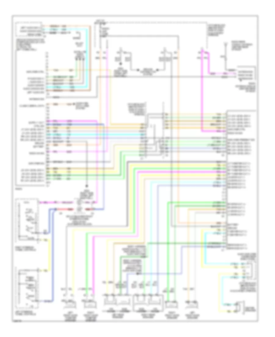 https://portal-diagnostov.com/license.html
Automotive Electricians Portal FZCO
Automotive Electricians Portal FZCO
https://portal-diagnostov.com/license.html
https://portal-diagnostov.com/license.html
Automotive Electricians Portal FZCO
Automotive Electricians Portal FZCOList of elements for Radio Wiring Diagram, with Amplifier for Pontiac Grand Prix GT 2006:
- (body harness, approximately 31.5 cm from breakout to audio amplifier) s318
- (body harness, approximately 7 cm from breakout to audio amplifier) s317
- 1-6
- A10
- A11
- A12
- Amplifier ctrl
- Amplifier present sig
- Amplifier sig
- Antenna sig
- Audio amplifier (under rear shelf panel)
- Audio common
- Audio common sig
- B10
- B11
- B12
- Band
- Bare
- Battery
- C10
- C12
- Center speaker
- Class 2 serial data
- Coax
- Computer data lines system
- Ctrl sig
- Down
- Drain wire
- F center out (+)
- F center out (-)
- G202 (right side upper left footwell)
- Ground
- Ground distribution system
- Hot at all times
- I/p fuse block (behind right side of dash, in glove box opening)
- Inflatable restraint steering wheel module coil (in steering column)
- L audio sig (+)
- Left audio sig
- Left audio sig (+)
- Left front door speaker
- Left front door tweeter speaker
- Left rear speaker
- Left steering
- Lf low level sig (+)
- Lf low level sig (-)
- Lf spkr out (+)
- Lf spkr out (-)
- Lf tweeter out (+)
- Lf tweeter out (-)
- Lr low level sig (+)
- Lr low level sig (-)
- Lr spkr out (+)
- Lr spkr out (-)
- Mid range
- Mute
- Nca
- Play
- R audio sig (+)
- Radio
- Radio antenna module (center rear of roof)
- Radio on sig
- Radio rear window antenna (center rear of roof)
- Radio/ amp fuse 25a
- Rear sub out (+)
- Rear sub out (-)
- Red
- Rf low level sig (+)
- Rf low level sig (-)
- Rf spkr out (+)
- Rf spkr out (-)
- Rf tweeter out (+)
- Rf tweeter out (-)
- Right front door speaker
- Right front door tweeter speaker
- Right rear speaker
- Right steering
- Rr low level sig (+)
- Rr low level sig (-)
- Rr spkr out (+)
- Rr spkr out (-)
- Satellite radio circuit
- Seek
- Seek down
- Sub- woofer
- Tan
- Vehicle communication interface module (vcim) (if equipped) (in trunk, on left wheelwell)
- Vol
- Wheel controls
Radio Wiring Diagram, without Amplifier for Pontiac Grand Prix GT 2006
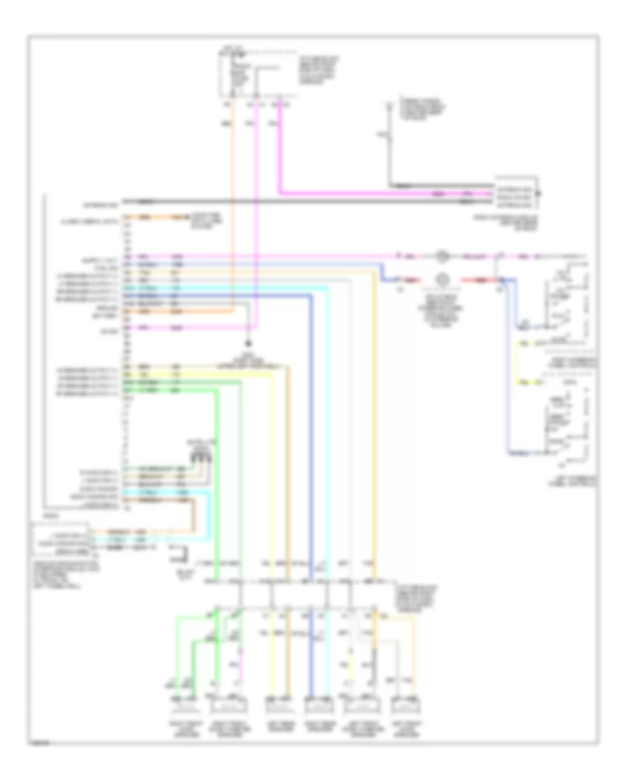 https://portal-diagnostov.com/license.html
Automotive Electricians Portal FZCO
Automotive Electricians Portal FZCO
https://portal-diagnostov.com/license.html
https://portal-diagnostov.com/license.html
Automotive Electricians Portal FZCO
Automotive Electricians Portal FZCOList of elements for Radio Wiring Diagram, without Amplifier for Pontiac Grand Prix GT 2006:
- 1-6
- A10
- A11
- A12
- A4 c1
- A9 c2
- Antenna sig
- Audio common
- Audio common sig
- B10
- B11
- B12
- Band
- Bare
- Battery
- C10
- C12
- Class 2 serial data
- Coax
- Computer data lines system
- Ctrl sig
- Drain wire
- G202 (right side upper left footwell)
- Ground
- Hot at all times
- I/p fuse block (behind right side of dash, in glove box opening)
- Inflatable restraint steering wheel module coil (in steering column)
- L audio sig (+)
- Left front door speaker
- Left front door tweeter speaker
- Left rear speaker
- Left steering wheel controls
- Lf speaker output (+)
- Lf speaker output (-)
- Lr speaker output (+)
- Lr speaker output (-)
- Mute
- Nca
- On sig
- Play
- R audio sig (+)
- Radio
- Radio antenna module (center rear of roof)
- Radio on sig
- Radio/ amp fuse 25a
- Rear window antenna radio (center rear of roof)
- Red
- Rf speaker output (+)
- Rf speaker output (-)
- Right front door speaker
- Right front door tweeter speaker
- Right rear speaker
- Right steering wheel controls
- Rr speaker output (+)
- Rr speaker output (-)
- Satellite radio circuit
- Seek down
- Seek up
- Tan
- Vehicle communication interface module (vcim) (if equipped) (in trunk, on left wheelwell)
- Vol down
- Vol up
Satellite Radio Wiring Diagram for Pontiac Grand Prix GT 2006
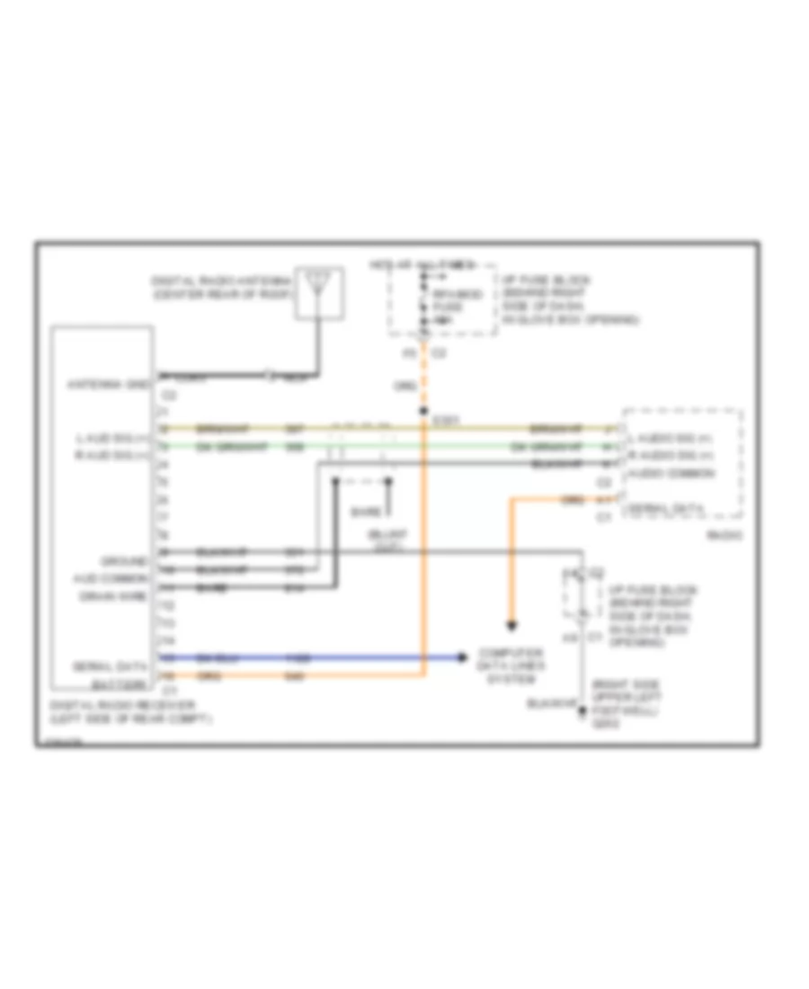 https://portal-diagnostov.com/license.html
Automotive Electricians Portal FZCO
Automotive Electricians Portal FZCO
https://portal-diagnostov.com/license.html
https://portal-diagnostov.com/license.html
Automotive Electricians Portal FZCO
Automotive Electricians Portal FZCOList of elements for Satellite Radio Wiring Diagram for Pontiac Grand Prix GT 2006:
- Antenna gnd
- Aud common
- Audio common
- Bare
- Battery
- Coax
- Computer data lines system
- Digital radio antenna (center rear of roof)
- Digital radio receiver (left side of rear compt)
- Drain wire
- Ground
- Hot at all times
- I/p fuse block (behind right side of dash, in glove box c1 opening)
- I/p fuse block (behind right side of dash, in glove box opening)
- L aud sig (+)
- L audio sig (+)
- Nca
- R aud sig (+)
- R audio sig (+)
- Radio
- Rfa/mod fuse 10a
- S301
- Serial data
SHIFT INTERLOCK
3.8L VIN 2
3.8L VIN 2, Shift Interlock Wiring Diagram for Pontiac Grand Prix GT 2006
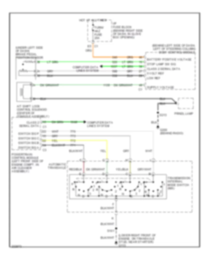 https://portal-diagnostov.com/license.html
Automotive Electricians Portal FZCO
Automotive Electricians Portal FZCO
https://portal-diagnostov.com/license.html
https://portal-diagnostov.com/license.html
Automotive Electricians Portal FZCO
Automotive Electricians Portal FZCOList of elements for 3.8L VIN 2, Shift Interlock Wiring Diagram for Pontiac Grand Prix GT 2006:
- (behind left side of dash, left of steering column) body control module
- (lower right front of engine, on transaxle stud, near starter) g113
- (under left side of dash) brake pedal position sensor
- 5 volt ref
- A/t shift lock control solenoid (center of console assembly)
- Automatic transaxle
- Battery positive voltage
- Class 2 serial data
- Class 2 serial data c1
- Computer data lines system
- E5 c1
- G200 (behind radio)
- Hot at all times
- I/p fuse block (behind right side of dash, in glove box opening)
- Low ref
- Powertrain control module (left front side of engine compt, in air cleaner assembly)
- Prndl lamp
- S101
- S213
- Stop lamp sw sig
- Switch sig a
- Switch sig b
- Switch sig c
- Switch sig p
- Transmission internal mode switch (ims)
- Turn/ haz fuse 20a
3.8L VIN 4
3.8L VIN 4, Shift Interlock Wiring Diagram for Pontiac Grand Prix GT 2006
 https://portal-diagnostov.com/license.html
Automotive Electricians Portal FZCO
Automotive Electricians Portal FZCO
https://portal-diagnostov.com/license.html
https://portal-diagnostov.com/license.html
Automotive Electricians Portal FZCO
Automotive Electricians Portal FZCOList of elements for 3.8L VIN 4, Shift Interlock Wiring Diagram for Pontiac Grand Prix GT 2006:
- (behind left side of dash, left of steering column) body control module
- (lower right front of engine, on transaxle stud, near starter) g113
- (under left side of dash) brake pedal position sensor
- 5 volt ref
- A/t shift lock control solenoid (center of console assembly)
- Automatic transaxle
- Battery positive voltage
- Class 2 serial data
- Class 2 serial data c1
- Computer data lines system
- E5 c1
- G200 (behind radio)
- Hot at all times
- I/p fuse block (behind right side of dash, in glove box opening)
- Low ref
- Powertrain control module (left front side of engine compt, in air cleaner assembly)
- Prndl lamp
- S101
- S213
- Stop lamp sw sig
- Switch sig a
- Switch sig b
- Switch sig c
- Switch sig p
- Transmission internal mode switch (ims)
- Turn/ haz fuse 20a
5.3L VIN C
5.3L VIN C, Shift Interlock Wiring Diagram for Pontiac Grand Prix GT 2006
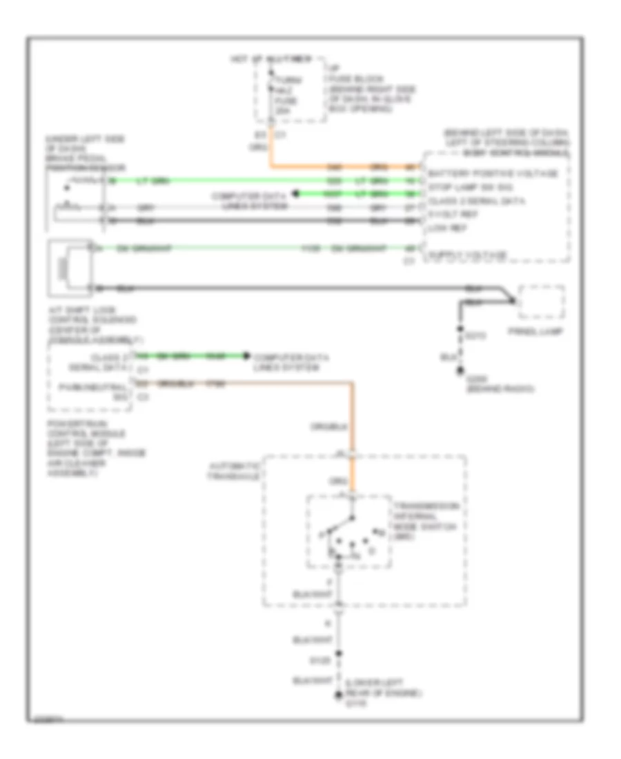 https://portal-diagnostov.com/license.html
Automotive Electricians Portal FZCO
Automotive Electricians Portal FZCO
https://portal-diagnostov.com/license.html
https://portal-diagnostov.com/license.html
Automotive Electricians Portal FZCO
Automotive Electricians Portal FZCOList of elements for 5.3L VIN C, Shift Interlock Wiring Diagram for Pontiac Grand Prix GT 2006:
- (behind left side of dash, left of steering column) body control module
- (lower left rear of engine) g115
- (under left side of dash) brake pedal position sensor
- 5 volt ref
- A/t shift lock control solenoid (center of console assembly)
- Automatic transaxle
- Battery positive voltage
- Class 2 serial data
- Class 2 serial data c1
- Computer data lines system
- E5 c1
- G200 (behind radio)
- Hot at all times
- I/p fuse block (behind right side of dash, in glove box opening)
- Low ref
- Park/neutral sig c3
- Powertrain control module (left side of engine compt, inside air cleaner assembly)
- Prndl lamp
- S125
- S213
- Stop lamp sw sig
- Transmission internal mode switch (ims)
- Turn/ haz fuse 20a
STARTING/CHARGING
Charging Wiring Diagram for Pontiac Grand Prix GT 2006
 https://portal-diagnostov.com/license.html
Automotive Electricians Portal FZCO
Automotive Electricians Portal FZCO
https://portal-diagnostov.com/license.html
https://portal-diagnostov.com/license.html
Automotive Electricians Portal FZCO
Automotive Electricians Portal FZCOList of elements for Charging Wiring Diagram for Pontiac Grand Prix GT 2006:
- (i/p harness, 6 cm from breakout to interior lamp switch) s204
- 5.3l
- Batt
- Battery
- Battery current sensor
- Battery positive voltage
- Bcm class 2
- Body control module (bcm) (behind left side of dash, left of steering column)
- Charging system failure ind
- Current sensor
- Data link connector (dlc) (under left side of dash, right of steering column)
- Displays fuse 10a
- Driver information center (dic)
- Ecm/tcm fuse 15a pcm/etc fuse 16 15a
- Except 5.3l
- G102 (right front of engine compt)
- G115 (lower left rear of engine)
- Generator
- Generator duty
- Generator turn on signal
- Gnd
- Hot at all times
- I/p dimming vol
- I/p fuse block (behind right side of dash, in glove box opening)
- Instrument panel cluster (ipc)
- Interior lights system
- Logic
- Low ref
- Message center
- Pcm class 2 serial data
- Powertrain control module (3.8l: left front side of engine compt, in air cleaner assembly) (5.3l: left side of engine compt, inside air cleaner assembly)
- Red
- Serial data
- Sp205 (clipped to knee-bolster panel, to right of data link connector)
- Starter
- Trip computer class 2 serial data
- Underhood fuse block (mounted to right strut tower)
- Volt
- Wsw/rvc fuse 15a washer/rvc fuse 6 15a
3.8L VIN 2
3.8L VIN 2, Starting Wiring Diagram for Pontiac Grand Prix GT 2006
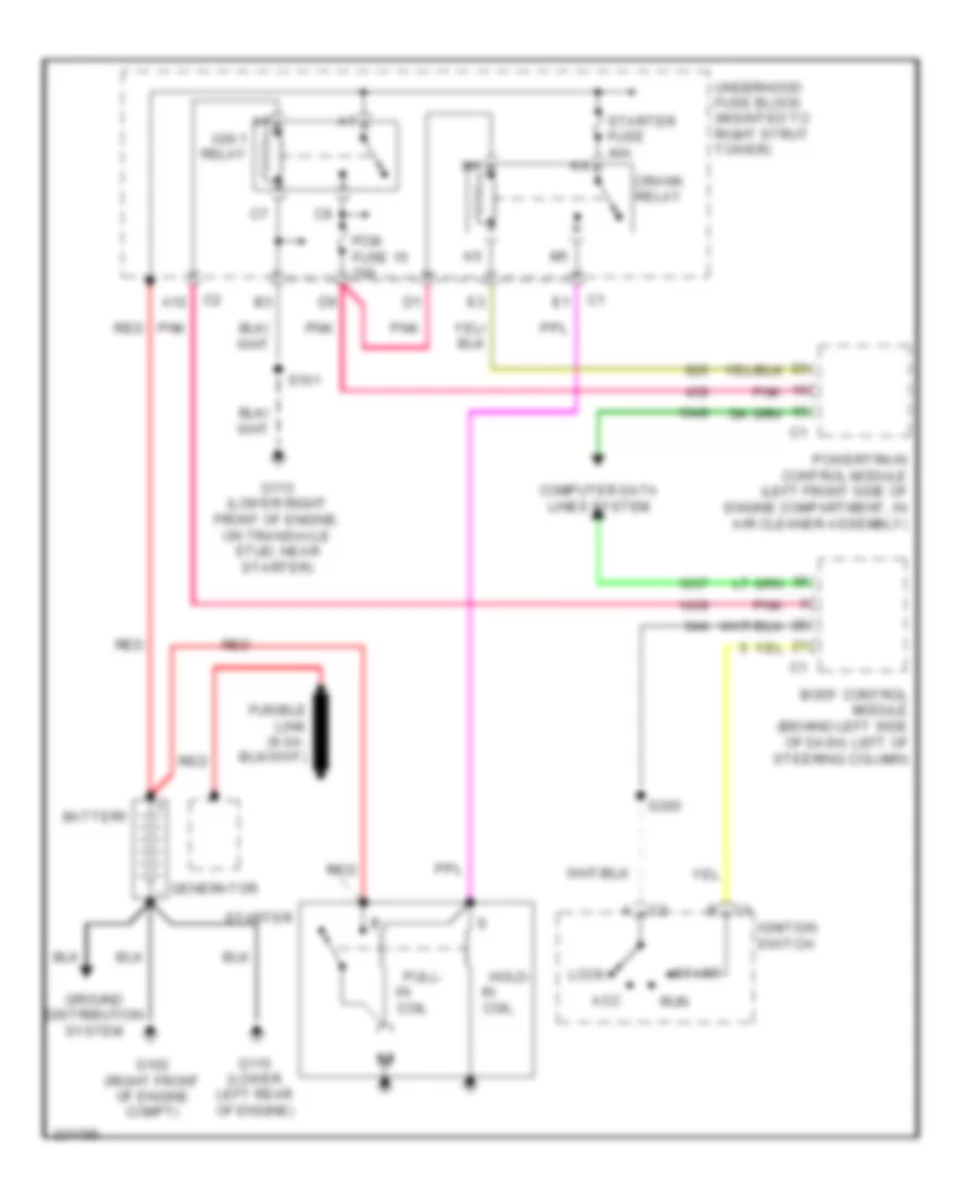 https://portal-diagnostov.com/license.html
Automotive Electricians Portal FZCO
Automotive Electricians Portal FZCO
https://portal-diagnostov.com/license.html
https://portal-diagnostov.com/license.html
Automotive Electricians Portal FZCO
Automotive Electricians Portal FZCOList of elements for 3.8L VIN 2, Starting Wiring Diagram for Pontiac Grand Prix GT 2006:
- A12
- Acc
- Battery
- Body control module (behind left side of dash, left of steering column)
- Coil
- Computer data lines system
- Crank relay
- G102 (right front of engine compt)
- G113 (lower right front of engine, on transaxle stud, near starter)
- G115 (lower left rear of engine)
- Generator
- Ground distribution system
- Hold-
- Ign 1 relay
- Ignition switch
- Lock
- Pcm fuse 15 10a
- Pnk
- Powertrain control module (left front side of engine compartment, in air cleaner assembly)
- Pull-
- Red
- Run
- S101
- S200
- Start
- Starter
- Starter fuse 40a
- Underhood fuse block (mounted to right strut tower)
3.8L VIN 4
3.8L VIN 4, Starting Wiring Diagram for Pontiac Grand Prix GT 2006
 https://portal-diagnostov.com/license.html
Automotive Electricians Portal FZCO
Automotive Electricians Portal FZCO
https://portal-diagnostov.com/license.html
https://portal-diagnostov.com/license.html
Automotive Electricians Portal FZCO
Automotive Electricians Portal FZCOList of elements for 3.8L VIN 4, Starting Wiring Diagram for Pontiac Grand Prix GT 2006:
- A12
- Acc
- Battery
- Body control module (behind left side of dash, left of steering column)
- Coil
- Computer data lines system
- Crank relay
- G102 (right front of engine compt)
- G113 (lower right front of engine, on transaxle stud, near starter)
- G115 (lower left rear of engine)
- Generator
- Ground distribution system
- Hold-
- Ign 1 relay
- Ignition switch
- Lock
- Pcm fuse 15 10a
- Pnk
- Powertrain control module (left front side of engine compartment, in air cleaner assembly)
- Pull-
- Red
- Run
- S101
- S200
- Start
- Starter
- Starter fuse 40a
- Underhood fuse block (mounted to right strut tower)
5.3L VIN C
5.3L VIN C, Starting Wiring Diagram for Pontiac Grand Prix GT 2006
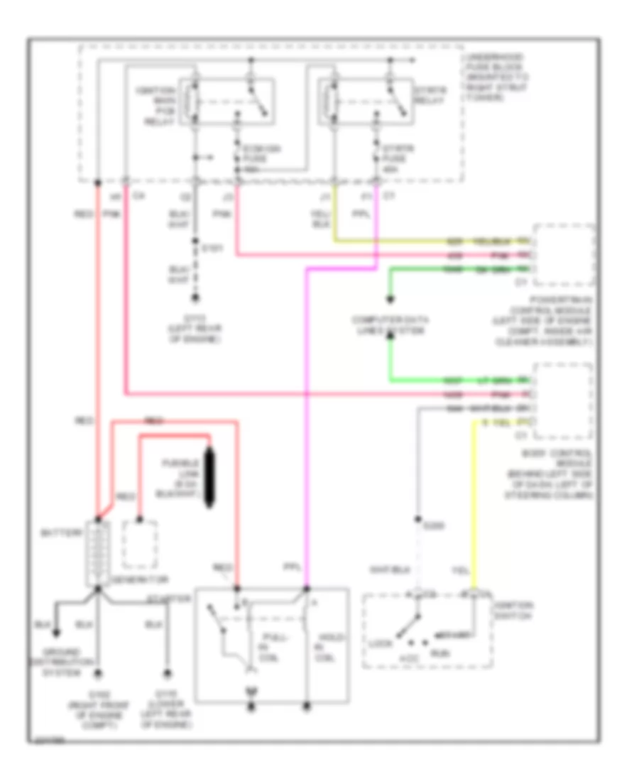 https://portal-diagnostov.com/license.html
Automotive Electricians Portal FZCO
Automotive Electricians Portal FZCO
https://portal-diagnostov.com/license.html
https://portal-diagnostov.com/license.html
Automotive Electricians Portal FZCO
Automotive Electricians Portal FZCOList of elements for 5.3L VIN C, Starting Wiring Diagram for Pontiac Grand Prix GT 2006:
- Acc
- Battery
- Body control module (behind left side of dash, left of steering column)
- Coil
- Computer data lines system
- Ecm ign fuse 10a
- G102 (right front of engine compt)
- G113 (left rear of engine)
- G115 (lower left rear of engine)
- Generator
- Ground distribution system
- Hold-
- Ignition main pcb relay
- Ignition switch
- Lock
- Pnk
- Powertrain control module (left side of engine compt, inside air cleaner assembly)
- Pull-
- Red
- Run
- S101
- S200
- Start
- Starter
- Strtr fuse 40a
- Strtr relay
- Underhood fuse block (mounted to right strut tower)
SUPPLEMENTAL RESTRAINTS
Supplemental Restraints Wiring Diagram (1 of 2) for Pontiac Grand Prix GT 2006
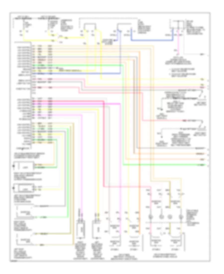 https://portal-diagnostov.com/license.html
Automotive Electricians Portal FZCO
Automotive Electricians Portal FZCO
https://portal-diagnostov.com/license.html
https://portal-diagnostov.com/license.html
Automotive Electricians Portal FZCO
Automotive Electricians Portal FZCOList of elements for Supplemental Restraints Wiring Diagram (1 of 2) for Pontiac Grand Prix GT 2006:
- (approximately 4.5 cm from breakout to seat belt switch) s330
- (at left front of engine compartment)
- (at right front of engine compartment)
- (right front door sill)
- 3.8l
- 5.3l
- A10
- A11
- A12
- A13
- A14
- A15
- A16
- A17
- A18
- Air bag/ display fuse 10a
- Case ground
- Computer data lines system
- Data link connector (dlc) (under left side of dash, right of steering column)
- G301 (left front door sill)
- G302
- G302 (right front door sill)
- Ground
- High control
- Hot w/ ign 1 relay energized
- Hot w/ ign main pcb relay energized
- I/p fuse block (behind right side of dash, in glove box opening)
- Ignition 1
- Inflatable restraint i/p module (behind right side of dash)
- Inflatable restraint sensing & diagnostic module (sdm) (under right front seat)
- Inflatable restraint steering wheel module
- Inflatable restraint steering wheel module coil (in steering column)
- L seat blt sw
- Left inflatable restraint front end sensor
- Left inflatable restraint side impact sensor (if equipped) (in driver's door)
- Left roof rail module (if equipped) (left rear of passenger compt)
- Left seat belt switch
- Lf sens sig
- Logic
- Low control
- Low ref
- Nca
- Pnk
- R seat blt sw
- Red
- Rf sens sig
- Right inflatable restraint front end sensor
- Right inflatable restraint side impact sensor (if equipped) (in front passenger's door)
- Right roof rail module (if equipped) (right rear of passenger compt)
- Right seat belt switch
- S303 (below left side of driver seat, approximately 19 cm from breakout to g301)
- S333 (front passenger seat harness, approximately 7 cm from breakout to right front seat belt pretensioner)
- Seat adjuster
- Serial data
- Shorting bar
- Signal
- Sir fuse 9 10a
- Splice pack sp205 (clipped to knee- bolster panel, to right of data link connector)
- Stage 1
- Stage 2
- Tan
- Underhood fuse block (mounted to right strut tower)
- Voltage
- W/ 6 way driver power
- W/o 6 way driver power
Supplemental Restraints Wiring Diagram (2 of 2) for Pontiac Grand Prix GT 2006
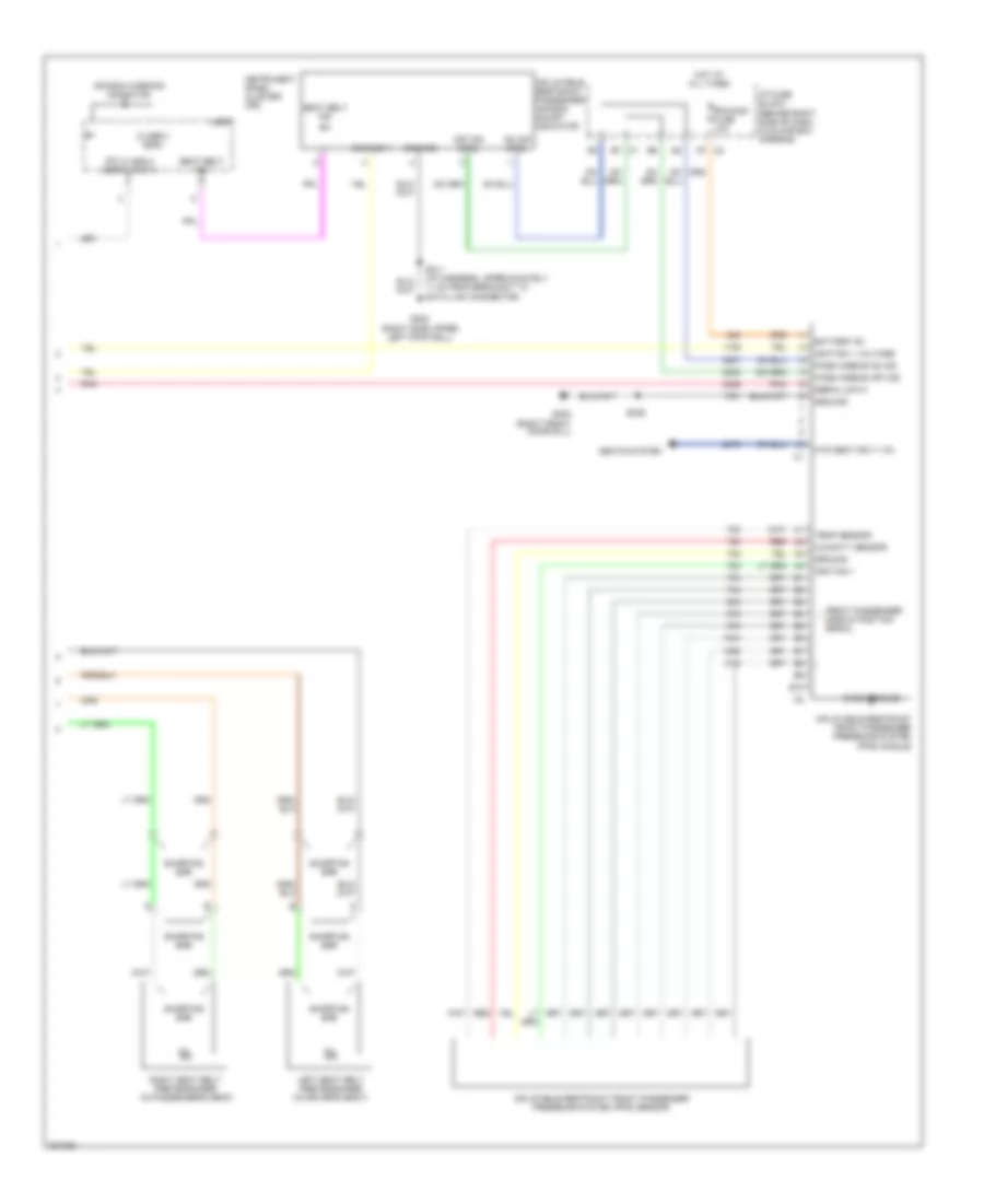 https://portal-diagnostov.com/license.html
Automotive Electricians Portal FZCO
Automotive Electricians Portal FZCO
https://portal-diagnostov.com/license.html
https://portal-diagnostov.com/license.html
Automotive Electricians Portal FZCO
Automotive Electricians Portal FZCOList of elements for Supplemental Restraints Wiring Diagram (2 of 2) for Pontiac Grand Prix GT 2006:
- Air bag warning indicator
- B10
- Battery b+
- Case ground
- Class 2 (sdm)
- Front passenger mass & position signal
- G202 (right side upper left footwell)
- G302 (right front door sill)
- Ground
- Hot at all times
- Htd seat sply vol
- Humidity sensor
- I/p fuse block (behind right side of dash, in glove box opening)
- Ignition 1
- Ignition 1 voltage
- Inflatable restraint front passenger presence system (pps) module
- Inflatable restraint front passenger presence system (pps) sensor
- Inflatable restraint passenger air bag on/off indicator
- Instrument panel cluster (ipc)
- Ipc class 2 serial data
- Left seat belt pretensioner (in driver's seat)
- Logic
- Off ind ctrl
- On ind ctrl
- Pass airbag off ind
- Pass airbag on ind
- Pnk
- Red
- Rfa/mod fuse 10a
- Right seat belt pretensioner (in passenger's seat)
- S211 (i/p harness, approximately 11 cm from breakout to data link connector)
- S306
- Seat belt ind
- Seats system
- Serial data
- Shorting bar
- Temp sensor
TRANSMISSION
3.8L VIN 2
3.8L VIN 2, A/T Wiring Diagram for Pontiac Grand Prix GT 2006
 https://portal-diagnostov.com/license.html
Automotive Electricians Portal FZCO
Automotive Electricians Portal FZCO
https://portal-diagnostov.com/license.html
https://portal-diagnostov.com/license.html
Automotive Electricians Portal FZCO
Automotive Electricians Portal FZCOList of elements for 3.8L VIN 2, A/T Wiring Diagram for Pontiac Grand Prix GT 2006:
- (approximately 4 cm from breakout to rcdlr)
- (in steering column) inflatable restraint steering wheel module coil
- (tft) sensor
- (vin 2: on top right of intake manifold) engine coolant temperature sensor
- (w/ manual shift) left tap shift switch
- (w/ manual shift) right tap shift switch
- 1-2 shift sol
- 1-2 shift solenoid (1-2 ss) valve
- 2-3 shift sol b
- 2-3 shift solenoid (2-3 ss) valve
- 3.8l (vin 4)
- 5 volt ref
- Acc
- At iss hi sig
- At iss low sig
- Automatic transaxle
- Automatic transmission fluid pressure (tfp) manual valve position
- Automatic transmission fluid temperature
- Battery
- Body control module (behind left side of dash, left of steering column)
- Computer data lines system
- Cruise sw fuse 2a
- D11
- Driver information center (dic)
- E12
- Ect sensor sig
- Engine controls system
- Front hi sig
- Front low sig
- G113 (lower right front of engine, on transaxle stud, near starter)
- Ground
- Hot at all times
- Hot in run or start
- I/p fuse block (behind right side of dash, in glove box opening)
- Ignition 1
- Ignition 3
- Ignition switch
- Input shaft speed sensor
- Lock
- Logic
- Low ref
- Manifold absolute pressure (map) sensor (vin 2: top right side of intake manifold) (vin 4: top right rear of engine, above valve cover)
- Map sensor sig
- Message center
- Pc sol vlv low
- Pcc sol vlv hi
- Pcm fuse 15 10a
- Pcm serial data
- Pcm/ etc fuse 16 15a
- Pnk
- Pnk b
- Power distribution system
- Powertrain control module (left front side of engine compt, in air cleaner assembly)
- Pressure control solenoid valve
- Prnd321
- Red
- Remote shift
- Run
- S101 (engine harness, approximately 5 cm from breakout to pcm)
- S115
- S201
- S240 (steering column harness)
- Serial data
- Start
- Stop lamp sw
- Stp lmp sw
- Switch
- Tan
- Tap dn
- Tap up
- Tcc sol
- Tcc sw sig
- Tft sensor sig
- Torque converter clutch (tcc) solenoid valve
- Tr sw a
- Tr sw b
- Tr sw c
- Tr sw p
- Trans sol fuse 21 10a
- Transmission internal mode switch
- Underhood fuse block (mounted to right strut tower)
- Vehicle speed sensor (lower right side of engine compt, on transaxle)
3.8L VIN 4
3.8L VIN 4, A/T Wiring Diagram for Pontiac Grand Prix GT 2006
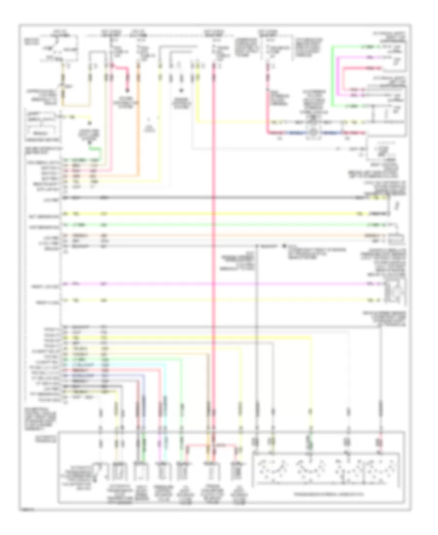 https://portal-diagnostov.com/license.html
Automotive Electricians Portal FZCO
Automotive Electricians Portal FZCO
https://portal-diagnostov.com/license.html
https://portal-diagnostov.com/license.html
Automotive Electricians Portal FZCO
Automotive Electricians Portal FZCOList of elements for 3.8L VIN 4, A/T Wiring Diagram for Pontiac Grand Prix GT 2006:
- (approximately 4 cm from breakout to rcdlr)
- (in steering column) inflatable restraint steering wheel module coil
- (tft) sensor
- (vin 2: on top right of intake manifold) engine coolant temperature sensor
- (w/ manual shift) left tap shift switch
- (w/ manual shift) right tap shift switch
- 1-2 shift sol
- 1-2 shift solenoid (1-2 ss) valve
- 2-3 shift sol b
- 2-3 shift solenoid (2-3 ss) valve
- 3.8l (vin 4)
- 5 volt ref
- Acc
- At iss hi sig
- At iss low sig
- Automatic transaxle
- Automatic transmission fluid pressure (tfp) manual valve position
- Automatic transmission fluid temperature
- Battery
- Body control module (behind left side of dash, left of steering column)
- Computer data lines system
- Cruise sw fuse 2a
- D11
- Driver information center (dic)
- E12
- Ect sensor sig
- Engine controls system
- Front hi sig
- Front low sig
- G113 (lower right front of engine, on transaxle stud, near starter)
- Ground
- Hot at all times
- Hot in run or start
- I/p fuse block (behind right side of dash, in glove box opening)
- Ignition 1
- Ignition 3
- Ignition switch
- Input shaft speed sensor
- Lock
- Logic
- Low ref
- Manifold absolute pressure (map) sensor (vin 2: top right side of intake manifold) (vin 4: top right rear of engine, above valve cover)
- Map sensor sig
- Message center
- Pc sol vlv low
- Pcc sol vlv hi
- Pcm fuse 15 10a
- Pcm serial data
- Pcm/ etc fuse 16 15a
- Pnk
- Pnk b
- Power distribution system
- Powertrain control module (left front side of engine compt, in air cleaner assembly)
- Pressure control solenoid valve
- Prnd321
- Red
- Remote shift
- Run
- S101 (engine harness, approximately 5 cm from breakout to pcm)
- S115
- S201
- S240 (steering column harness)
- Serial data
- Start
- Stop lamp sw
- Stp lmp sw
- Switch
- Tan
- Tap dn
- Tap up
- Tcc sol
- Tcc sw sig
- Tft sensor sig
- Torque converter clutch (tcc) solenoid valve
- Tr sw a
- Tr sw b
- Tr sw c
- Tr sw p
- Trans sol fuse 21 10a
- Transmission internal mode switch
- Underhood fuse block (mounted to right strut tower)
- Vehicle speed sensor (lower right side of engine compt, on transaxle)
5.3L VIN C
5.3L VIN C, A/T Wiring Diagram for Pontiac Grand Prix GT 2006
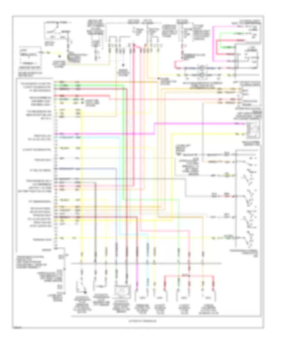 https://portal-diagnostov.com/license.html
Automotive Electricians Portal FZCO
Automotive Electricians Portal FZCO
https://portal-diagnostov.com/license.html
https://portal-diagnostov.com/license.html
Automotive Electricians Portal FZCO
Automotive Electricians Portal FZCOList of elements for 5.3L VIN C, A/T Wiring Diagram for Pontiac Grand Prix GT 2006:
- (behind left side of dash, left steering column) body control module (bcm)
- (lower left rear of engine) g115
- (steering column harness) s240
- (w/ manual shift) right tap shift switch
- 1-2 shift solenoid (1-2 ss) valve
- 1-2 shift solenoid ctrl
- 2-3 shift solenoid (2-3 ss) valve
- 2-3 shift solenoid ctrl
- Acc
- At iss high signal
- At iss low signal
- Automatic transaxle
- Automatic transmission fluid pressure (tfp) manual valve position switch
- Automatic transmission fluid temperature (tft) sensor
- Automatic transmission input shaft speed (at iss) sensor
- Battery positive voltage
- Bus +
- Bus -
- Computer data lines system
- Cruise sw fuse 2a
- Driver information center (dic)
- E12
- Ecm/tcm fuse 1 15a
- Engine controls system
- Front sig high
- Front sig low
- G115 (lower left rear of engine)
- Gmlan data bus +
- Gmlan data bus -
- Ground
- Hot at all times
- Hot in on or start
- I/p fuse block (behind right side of dash, in glove box opening)
- Ign vol 3
- Ignition 1 voltage
- Ignition switch
- Inflatable restraint steering wheel module coil (in steering column)
- Left tap shift switch (w/ manual shift)
- Lock
- Logic
- Low reference
- Message center
- Nca
- P/n sig
- Pc valve high ctrl
- Pc valve low ctrl
- Pnk
- Power distribution system
- Powertrain control module (left side of engine compartment, inside air cleaner assembly)
- Pressure control (pc) solenoid valve
- Prnd321
- R p
- Red
- Remote shft sel sig
- Run
- S115
- S125 (approximately 5 cm from breakout to left front wheel speed sensor)
- Sae serial bus +
- Sae serial bus -
- Serial data
- Start
- Stop lamp sw
- Stop lamp sw sig
- Tan
- Tap
- Tap dn
- Tap down
- Tap up
- Tcc release sw sig
- Tcc solenoid valve ctrl
- Tft sensor signal
- Torque converter clutch (tcc) solenoid valve
- Tran range sw sig a
- Tran sw sig c
- Trans fuse 10a
- Trans sw sig b
- Trans sw sig p
- Transmission control module (tcm) (left side of engine compartment, inside air cleaner assembly)
- Transmission internal mode switch (ims)
- Underhood fuse block (mounted to right strut tower)
- Vehicle sig
- Vehicle speed sensor (vss)
- Vehicle speed sig
TRUNK, TAILGATE, FUEL DOOR
Trunk Release Wiring Diagram for Pontiac Grand Prix GT 2006
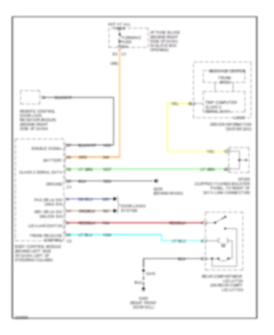 https://portal-diagnostov.com/license.html
Automotive Electricians Portal FZCO
Automotive Electricians Portal FZCO
https://portal-diagnostov.com/license.html
https://portal-diagnostov.com/license.html
Automotive Electricians Portal FZCO
Automotive Electricians Portal FZCOList of elements for Trunk Release Wiring Diagram for Pontiac Grand Prix GT 2006:
- Battery
- Body control module (behind left side of dash, left of steering column)
- Class 2 serial data
- Door locks system
- Driver information center (dic)
- Drv dr lk sw unlock sig
- E5 c1
- Enable signal
- G200 (behind radio)
- G302 (right front door sill)
- Ground
- Hot at all times
- I/p fuse block (behind right side of dash, in glove box opening)
- Lid ajar switch
- Logic
- Message center
- Pas dr lk sw unlk sig
- Rear compartment lid latch (on rear compt lid latch)
- Remote control door lock receiver (rcdlr) (behind right side of dash)
- S416
- Sp205 (clipped to knee-bolster panel, to right of data link connector)
- Trip computer class 2 serial data
- Trunk open
- Trunk release control c2
- Turn/haz fuse 20a
WARNING SYSTEMS
Warning Systems Wiring Diagram for Pontiac Grand Prix GT 2006
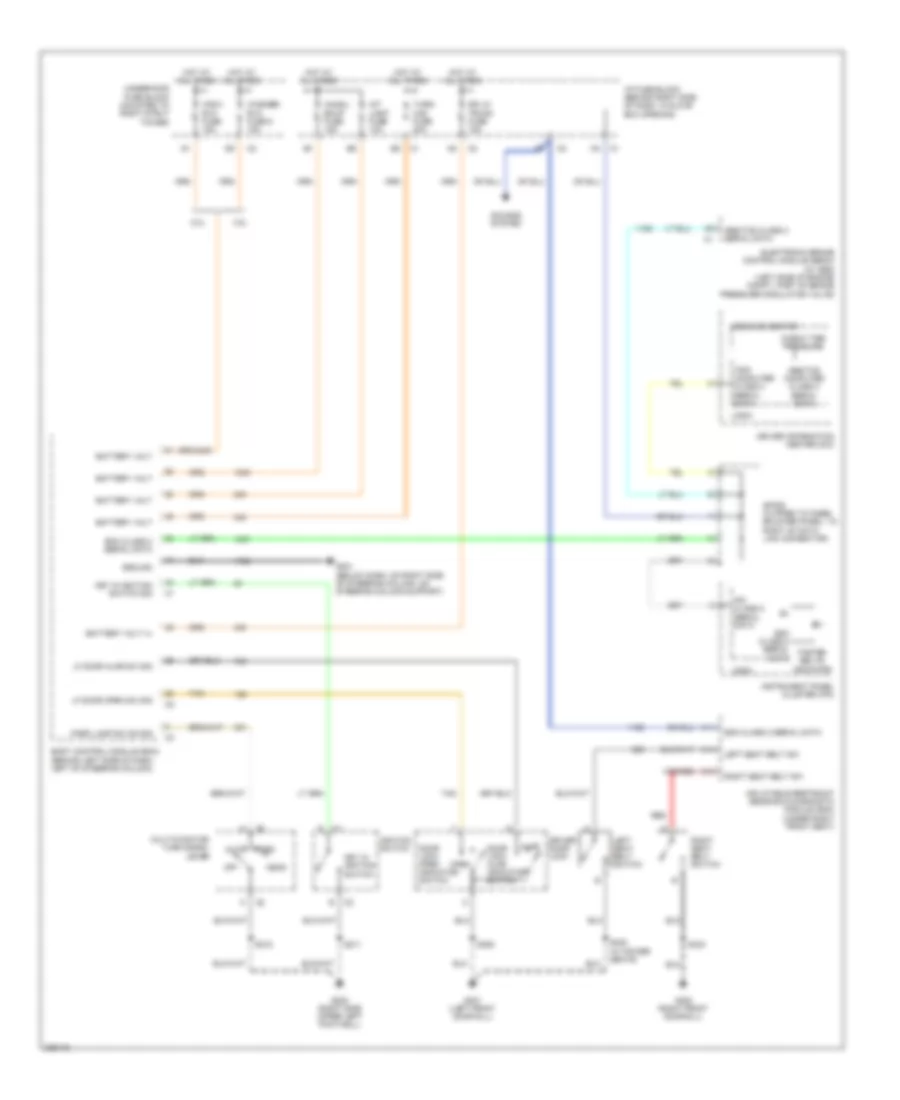 https://portal-diagnostov.com/license.html
Automotive Electricians Portal FZCO
Automotive Electricians Portal FZCO
https://portal-diagnostov.com/license.html
https://portal-diagnostov.com/license.html
Automotive Electricians Portal FZCO
Automotive Electricians Portal FZCOList of elements for Warning Systems Wiring Diagram for Pontiac Grand Prix GT 2006:
- 3.8l
- 5.3l
- A11
- A14
- A16
- Abs/tcs class 2 serial data
- Abs/tcs computer class 2 serial data
- Ajar
- Auto
- Battery volt
- Battery volt (+)
- Bcm class 2 serial data
- Body control module (bcm) (behind left side of dash, left of steering column)
- Check tire pressure
- Chmsl/ bkup fuse 15a
- Door lock ajar indicator switch
- Door lock open indicator switch
- Dr lk/ trunk fuse 15a
- Driver door lock
- Driver information center (dic)
- Electronic brake control module (ebcm) (w/ abs) (left side of engine compt, part of brake pressure modulator valve)
- Fasten belts indicator
- G201 (below dash, on right side of steering column, on steering column support)
- G202 (right side upper left footwell)
- G301 (left front door sill)
- G302 (right front door sill)
- Ground
- Head
- Hot at all times
- I/p fuse block (behind right side of dash, in glove box opening)
- Ignition switch
- Inflatable restraint sensing & diagnostic module (sdm) (under right front seat)
- Instrument panel cluster (ipc)
- Int light fuse 10a
- Ipc class 2 serial data
- Key in ignition switch
- Key in ignition switch sig
- Left seat belt sw
- Left seat belt switch
- Lf door ajar sw sig
- Lf door open sw sig
- Logic
- Message center
- Multi-function turn signal lever
- Off
- Open
- Park
- Park lamp sw on sig
- Red
- Right seat belt sw
- Right seat belt switch
- S211
- S215
- S305
- S330 (w/ power seats)
- S333
- Sdm class 2 serial data
- Sounds system
- Sp205 (clipped to knee- bolster panel, to right of data link connector)
- Tan
- Trip computer class 2 serial data
- Turn/ haz fuse 20a
- Underhood fuse block (mounted to right strut tower)
- Washer/ rvc fuse 6 15a
- Wsw/ rvc fuse 15a
WIPER/WASHER
3.8L VIN 2
3.8L VIN 2, Wiper/Washer Wiring Diagram for Pontiac Grand Prix GT 2006
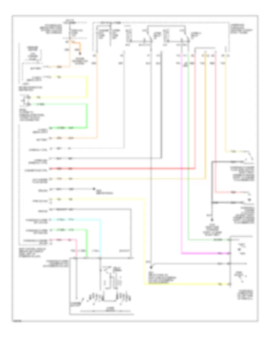 https://portal-diagnostov.com/license.html
Automotive Electricians Portal FZCO
Automotive Electricians Portal FZCO
https://portal-diagnostov.com/license.html
https://portal-diagnostov.com/license.html
Automotive Electricians Portal FZCO
Automotive Electricians Portal FZCOList of elements for 3.8L VIN 2, Wiper/Washer Wiring Diagram for Pontiac Grand Prix GT 2006:
- A14
- A15
- B14
- Battery
- Body control module (behind left side of dash, left of steering column)
- C14
- C15
- C2 f4
- Class 2 serial data
- D5 c3
- Delay switch
- Displays fuse 10a
- Driver information center (dic)
- E14
- E15
- F10
- F11
- F12
- F14
- G100 (right side of engine compt, at base of battery)
- G14
- G15
- G200 (behind radio)
- G201 (below dash, on right side of steering column, on steering column support)
- Ground
- High
- Hot at all times
- I/p fuse block (behind right side of dash, in glove box opening)
- Int
- Logic
- Low
- Low washer fluid
- Low washer fluid ind sig
- Message center
- Mist
- Off
- Park sw sig
- Park switch
- Pnk
- Power distribution system
- Red
- S124
- Sp205 (clipped to knee-bolster panel, to right of data link connector)
- Tan
- Underhood fuse block (mounted to right strut tower)
- Washer pump ctrl
- Washer switch
- Washer/ rvc fuse 15a
- Windshield washer fluid level switch (right front corner of engine compt, in washer fluid reservoir)
- Windshield washer fluid pump (on right front corner of engine compt, in washer fluid reservoir)
- Windshield washer sw sig c3
- Windshield wiper motor (on left side of firewall)
- Windshield wiper sw high sig
- Windshield wiper sw low sig
- Windshield wiper/ washer switch (on steering column)
- Wiper hi relay
- Wiper high speed rly ctrl
- Wiper relay
- Wiper rly ctrl
- Wiper switch
- Wiper/ ws fuse 25a
3.8L VIN 4
3.8L VIN 4, Wiper/Washer Wiring Diagram for Pontiac Grand Prix GT 2006
 https://portal-diagnostov.com/license.html
Automotive Electricians Portal FZCO
Automotive Electricians Portal FZCO
https://portal-diagnostov.com/license.html
https://portal-diagnostov.com/license.html
Automotive Electricians Portal FZCO
Automotive Electricians Portal FZCOList of elements for 3.8L VIN 4, Wiper/Washer Wiring Diagram for Pontiac Grand Prix GT 2006:
- A14
- A15
- B14
- Battery
- Body control module (behind left side of dash, left of steering column)
- C14
- C15
- C2 f4
- Class 2 serial data
- D5 c3
- Delay switch
- Displays fuse 10a
- Driver information center (dic)
- E14
- E15
- F10
- F11
- F12
- F14
- G100 (right side of engine compt, at base of battery)
- G14
- G15
- G200 (behind radio)
- G201 (below dash, on right side of steering column, on steering column support)
- Ground
- High
- Hot at all times
- I/p fuse block (behind right side of dash, in glove box opening)
- Int
- Logic
- Low
- Low washer fluid
- Low washer fluid ind sig
- Message center
- Mist
- Off
- Park sw sig
- Park switch
- Pnk
- Power distribution system
- Red
- S124
- Sp205 (clipped to knee-bolster panel, to right of data link connector)
- Tan
- Underhood fuse block (mounted to right strut tower)
- Washer pump ctrl
- Washer switch
- Washer/ rvc fuse 15a
- Windshield washer fluid level switch (right front corner of engine compt, in washer fluid reservoir)
- Windshield washer fluid pump (on right front corner of engine compt, in washer fluid reservoir)
- Windshield washer sw sig c3
- Windshield wiper motor (on left side of firewall)
- Windshield wiper sw high sig
- Windshield wiper sw low sig
- Windshield wiper/ washer switch (on steering column)
- Wiper hi relay
- Wiper high speed rly ctrl
- Wiper relay
- Wiper rly ctrl
- Wiper switch
- Wiper/ ws fuse 25a
5.3L VIN C
5.3L VIN C, Wiper/Washer Wiring Diagram for Pontiac Grand Prix GT 2006
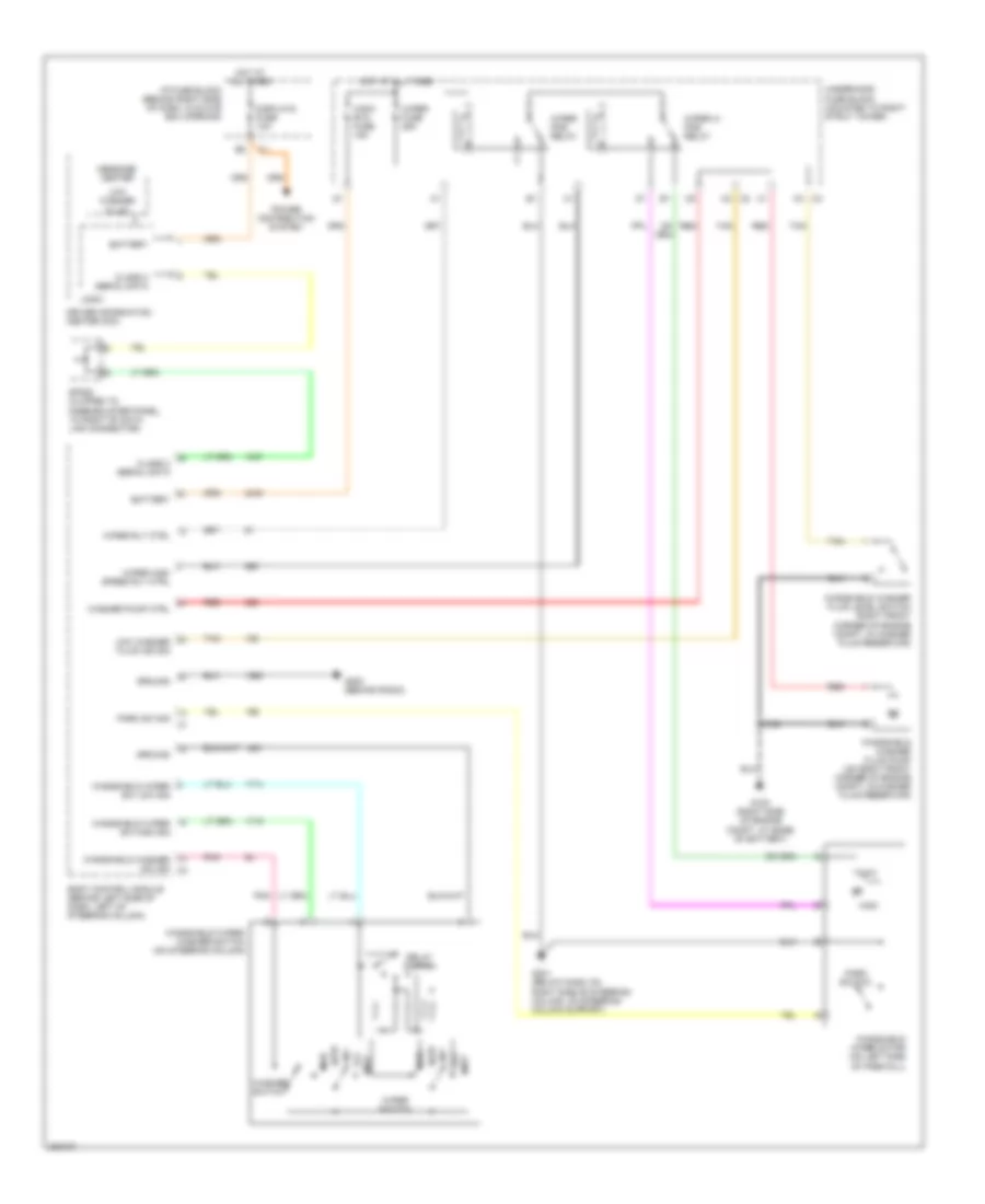 https://portal-diagnostov.com/license.html
Automotive Electricians Portal FZCO
Automotive Electricians Portal FZCO
https://portal-diagnostov.com/license.html
https://portal-diagnostov.com/license.html
Automotive Electricians Portal FZCO
Automotive Electricians Portal FZCOList of elements for 5.3L VIN C, Wiper/Washer Wiring Diagram for Pontiac Grand Prix GT 2006:
- Battery
- Body control module (behind left side of dash, left of steering column)
- C2 k4
- Class 2 serial data
- Delay switch
- Displays fuse 10a
- Driver information center (dic)
- G100 (right side of engine compt, at base of battery)
- G200 (behind radio)
- G201 (below dash, on right side of steering column, on steering column support)
- Ground
- High
- Hot at all times
- I/p fuse block (behind right side of dash, in glove box opening)
- Int
- K3 c3
- Logic
- Low
- Low washer fluid
- Low washer fluid ind sig
- Message center
- Mist
- Off
- Park sw sig
- Park switch
- Pnk
- Power distribution system
- Red
- S124
- Sp205 (clipped to knee-bolster panel, to right of data link connector)
- Tan
- Underhood fuse block (mounted to right strut tower)
- Washer pump ctrl
- Washer switch
- Windshield washer fluid level switch (right front corner of engine compt, in washer fluid reservoir)
- Windshield washer fluid pump (on right front corner of engine compt, in washer fluid reservoir)
- Windshield washer sw sig c3
- Windshield wiper motor (on left side of firewall)
- Windshield wiper sw high sig
- Windshield wiper sw low sig
- Windshield wiper/ washer switch (on steering column)
- Wiper fuse 25a
- Wiper hi pcb relay
- Wiper high speed rly ctrl
- Wiper pcb relay
- Wiper rly ctrl
- Wiper switch
- Wsw/ rvc fuse 15a

 Čeština
 Dansk
Dansk Deutsch
 Ελληνικά
 English
 English
 Español
 Suomi
Suomi Français
 Français
 עברית
עברית Hrvatski
 Magyar
 Italiano
 日本語
日本語 한국어
한국어 Nederlands
 Polski
 Português
 Português
 Română
 Русский
 Slovenčina
 Slovenščina
 Svenska
 Türkçe
