ANTI-LOCK BRAKES
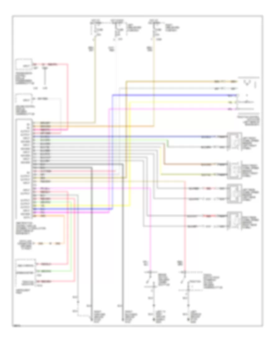
Anti-lock Brake Wiring Diagrams for Jaguar XJ6 L 1997
List of elements for Anti-lock Brake Wiring Diagrams for Jaguar XJ6 L 1997:
- (driver's "a" post)
- (left "a" post ground screw) g202
- (left console ground stud) g206
- (right bulkhead ground stud) g123
- (right forward ground stud) g107
- Abs warning
- Abs/traction control module (integral w/ modulator) (right rear of engine bay)
- Brake switch (driver's under- scuttle)
- Ca1
- Ca36
- Cc48
- Cc7
- Cruise control module (driver's underscuttle)
- Data
- Data link connector
- Fascia switch pack (steering column, driver's underscuttle)
- Fc10
- Fc9
- Fuse 30a
- Fuse 5a
- Hot at all times
- Hot in run & start
- Input
- Instrument pack
- Left front wheel speed sensor (left front wheel)
- Left heelboard fuse box
- Left rear wheel speed sensor (left rear wheel)
- Nca
- Output
- Red
- Right front wheel speed sensor (right front wheel)
- Right heelboard fuse box
- Right rear wheel speed sensor (right rear wheel)
- Sig gnd
- Speedometer
- Traction
- Traction control actuator (left rear of engine bay)
- Traction indicator
- Transmission control module (passenger's underscuttle)
- Xj6
- Xjr
 Čeština
 Dansk
Dansk Deutsch
 Ελληνικά
 English
 English
 Suomi
Suomi Français
 Français
 עברית
עברית Hrvatski
 Magyar
 Italiano
 日本語
日本語 한국어
한국어 Nederlands
 Polski
 Português
 Português
 Română
 Русский
 Slovenčina
 Slovenščina
 Svenska
 Türkçe
 中文 (中国)
 Español