ENGINE PERFORMANCE
4.0L
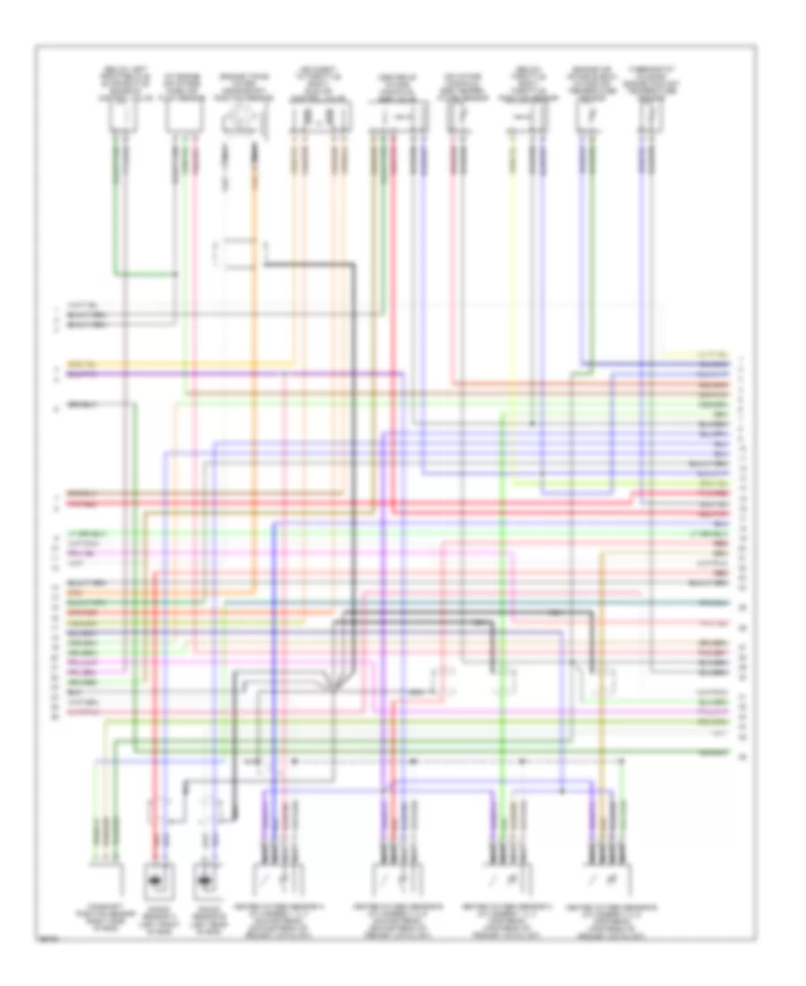
4.0L, Engine Performance Wiring Diagrams (1 of 3) for Jaguar XJ6 L 1997

List of elements for 4.0L, Engine Performance Wiring Diagrams (1 of 3) for Jaguar XJ6 L 1997:
- (front trunk ground stud, right front side of trunk)
- (inside fuel tank) fuel pump
- (left console ground stud)
- (right bulkhead ground stud, right side of safety wall)
- (trunk electrical carrier) fuel pump relay
- 20a
- Acc
- Air conditioning system
- Bt35
- C10
- Ca2
- Ca44
- Ecm control relay (in right engine bay relays)
- Engine control module (at right "a" post)
- Fuel injectors
- Fuse
- Fuse 10 5a
- Fuse 10a
- Fuse 7 30a
- G123
- G203 (right "a" post ground stud, right kick panel)
- G206
- G401
- High power (black)
- Hot at all times
- Ignition coils
- Ignition positive relay
- Ignition switch
- Inertia switch (right "a" post)
- Nca
- Off
- Pnk/red
- Power fuse 250a
- Power fuse box (below right rear seat)
- Right engine bay fuse box (right front of eng compt)
- Right heelboard fuse box (below right rear seat)
- Rs1
- Rs6
- Run
- Security & locking control module (under left rear seat)
- Start
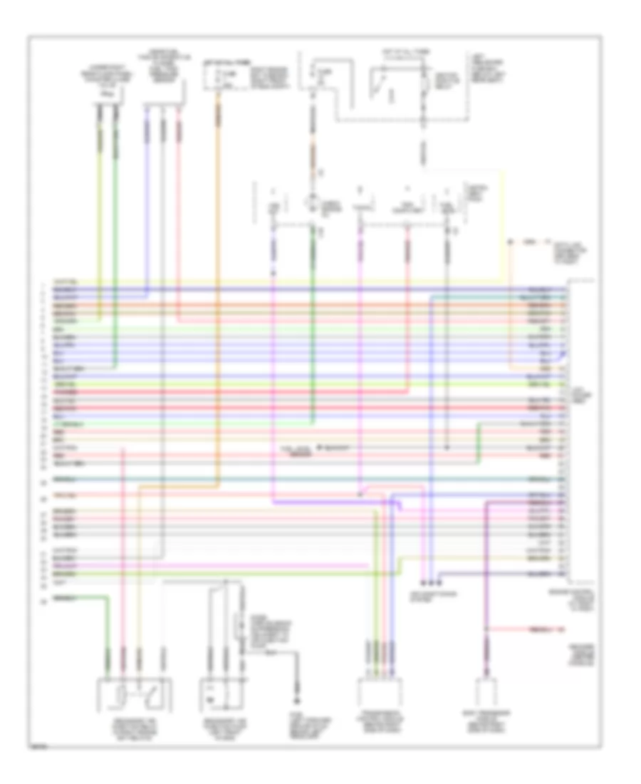
4.0L, Engine Performance Wiring Diagrams (2 of 3) for Jaguar XJ6 L 1997
List of elements for 4.0L, Engine Performance Wiring Diagrams (2 of 3) for Jaguar XJ6 L 1997:
- (adjacent to throttle body) idle air control valve
- (at engine air intake) mass air flow sensor
- (below left front relays) evaporative emission control valve
- (below throttle body) throttle position sensor
- (center of intake manifold) egr valve
- (engine air intake elbow) intake air temperature sensor
- (engine timing cover) crankshaft position sensor
- (on intake manifold) egr temper- ature sensor
- (thermostat housing) engine coolant temperature sensor
- Camshaft position sensor (right side of eng)
- Heated oxygen sensor a (cylinders 1, 2, 3 downstream) (downstream of primary catalyst)
- Heated oxygen sensor a (cylinders 1, 2, 3 upstream) (upstream of primary catalyst)
- Heated oxygen sensor b (cylinders 4, 5, 6 downstream) (downstream of primary catalyst)
- Heated oxygen sensor b (cylinders 4, 5, 6 upstream) (upstream of primary catalyst)
- Knock sensor a (left front of eng)
- Knock sensor b (left rear of eng)
- Nca
- Pnk/red
- Red
- Red/pnk
4.0L, Engine Performance Wiring Diagrams (3 of 3) for Jaguar XJ6 L 1997
List of elements for 4.0L, Engine Performance Wiring Diagrams (3 of 3) for Jaguar XJ6 L 1997:
- (near fuel tank evaporative flange) fuel tank pressure sensor
- (under right rear floor panel) canister close valve
- Air conditioning system
- Body processor module (behind right side of dash)
- C10
- Check engine mil
- Computer
- Data link connector (driver's "a" post)
- Decoder module (center console)
- Diode (airp solenoid suppression) (adjacent to air injection pump)
- Engine control module (at right "a" post)
- Fuel level
- Fuel level sensor
- Fuse 25a
- Fuse 5a
- G106 (left forward ground stud, behind left headlamp)
- Hot at all times
- Ignition positive relay
- Instru- ment pack
- Left heelboard fuse box (below left rear seat)
- Low power (red)
- Nca
- Pnk/red
- Red
- Red/pnk
- Right engine bay fuse box (right front of eng compt)
- Secondary air injection pump (left front of eng)
- Secondary air injection relay (in right engine bay relays)
- Tacho
- Transmission control module (behind right side of dash)
- Trip
- Vss out