ENGINE PERFORMANCE
4.0L
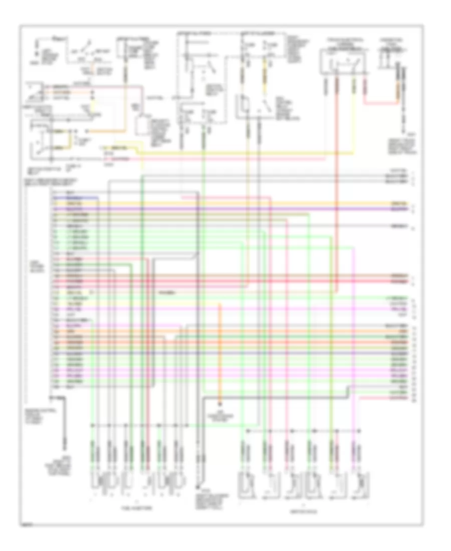
4.0L, Engine Performance Wiring Diagrams (1 of 3) for Jaguar XJ6 L 1997
List of elements for 4.0L, Engine Performance Wiring Diagrams (1 of 3) for Jaguar XJ6 L 1997:
- (front trunk ground stud, right front side of trunk)
- (inside fuel tank) fuel pump
- (left console ground stud)
- (right bulkhead ground stud, right side of safety wall)
- (trunk electrical carrier) fuel pump relay
- 20a
- Acc
- Air conditioning system
- Bt35
- C10
- Ca2
- Ca44
- Ecm control relay (in right engine bay relays)
- Engine control module (at right "a" post)
- Fuel injectors
- Fuse
- Fuse 10 5a
- Fuse 10a
- Fuse 7 30a
- G123
- G203 (right "a" post ground stud, right kick panel)
- G206
- G401
- High power (black)
- Hot at all times
- Ignition coils
- Ignition positive relay
- Ignition switch
- Inertia switch (right "a" post)
- Nca
- Off
- Pnk/red
- Power fuse 250a
- Power fuse box (below right rear seat)
- Right engine bay fuse box (right front of eng compt)
- Right heelboard fuse box (below right rear seat)
- Rs1
- Rs6
- Run
- Security & locking control module (under left rear seat)
- Start
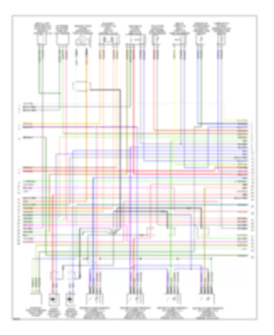
4.0L, Engine Performance Wiring Diagrams (2 of 3) for Jaguar XJ6 L 1997
List of elements for 4.0L, Engine Performance Wiring Diagrams (2 of 3) for Jaguar XJ6 L 1997:
- (adjacent to throttle body) idle air control valve
- (at engine air intake) mass air flow sensor
- (below left front relays) evaporative emission control valve
- (below throttle body) throttle position sensor
- (center of intake manifold) egr valve
- (engine air intake elbow) intake air temperature sensor
- (engine timing cover) crankshaft position sensor
- (on intake manifold) egr temper- ature sensor
- (thermostat housing) engine coolant temperature sensor
- Camshaft position sensor (right side of eng)
- Heated oxygen sensor a (cylinders 1, 2, 3 downstream) (downstream of primary catalyst)
- Heated oxygen sensor a (cylinders 1, 2, 3 upstream) (upstream of primary catalyst)
- Heated oxygen sensor b (cylinders 4, 5, 6 downstream) (downstream of primary catalyst)
- Heated oxygen sensor b (cylinders 4, 5, 6 upstream) (upstream of primary catalyst)
- Knock sensor a (left front of eng)
- Knock sensor b (left rear of eng)
- Nca
- Pnk/red
- Red
- Red/pnk
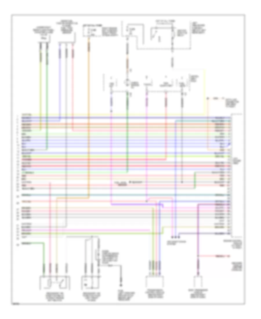
4.0L, Engine Performance Wiring Diagrams (3 of 3) for Jaguar XJ6 L 1997
List of elements for 4.0L, Engine Performance Wiring Diagrams (3 of 3) for Jaguar XJ6 L 1997:
- (near fuel tank evaporative flange) fuel tank pressure sensor
- (under right rear floor panel) canister close valve
- Air conditioning system
- Body processor module (behind right side of dash)
- C10
- Check engine mil
- Computer
- Data link connector (driver's "a" post)
- Decoder module (center console)
- Diode (airp solenoid suppression) (adjacent to air injection pump)
- Engine control module (at right "a" post)
- Fuel level
- Fuel level sensor
- Fuse 25a
- Fuse 5a
- G106 (left forward ground stud, behind left headlamp)
- Hot at all times
- Ignition positive relay
- Instru- ment pack
- Left heelboard fuse box (below left rear seat)
- Low power (red)
- Nca
- Pnk/red
- Red
- Red/pnk
- Right engine bay fuse box (right front of eng compt)
- Secondary air injection pump (left front of eng)
- Secondary air injection relay (in right engine bay relays)
- Tacho
- Transmission control module (behind right side of dash)
- Trip
- Vss out

 Čeština
 Dansk
Dansk Deutsch
 English
 English
 Español
 Suomi
Suomi Français
 Français
 עברית
עברית Hrvatski
 Magyar
 Italiano
 日本語
日本語 한국어
한국어 Nederlands
 Polski
 Português
 Português
 Română
 Русский
 Slovenčina
 Slovenščina
 Svenska
 Türkçe
 中文 (中国)