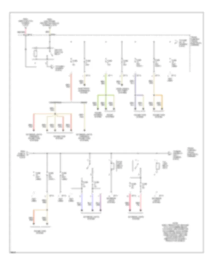
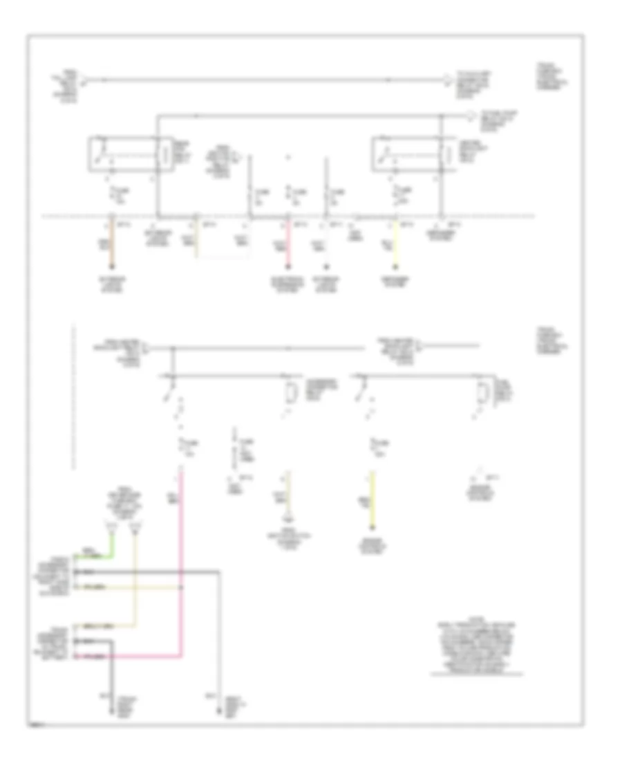
POWER DISTRIBUTION
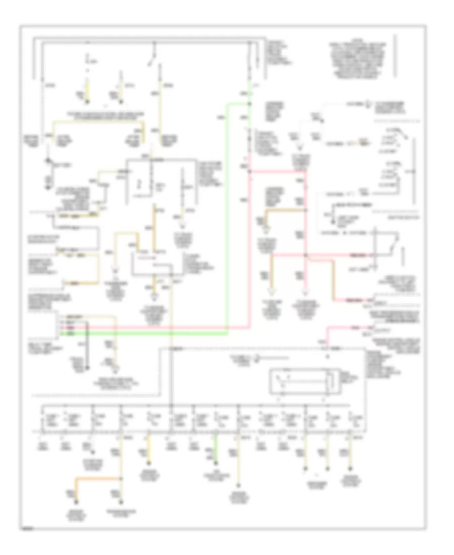
Power Distribution Wiring Diagram (1 of 6) for Jaguar XK8 1997
List of elements for Power Distribution Wiring Diagram (1 of 6) for Jaguar XK8 1997:
- (0) off
- (i) acc
- (ii) run
- (iii) start
- (left hand "a" post) g202
- (not used)
- (trunk, right rear) g405
- 250a
- 250a (x2)
- 25a
- After dealer prep
- Air conditioning system
- An1
- Battery
- Before dealer prep
- Body processor module (passenger side fascia, airbag bracket)
- Bt44
- Bt60
- Bt61
- Bt62
- Bt63
- Bt65
- Bt66
- Bt79
- Bt80
- Defogger system
- Delay timer (trunk, adjacent to battery)
- Em10
- Em19
- Em20
- Em70
- Em71
- Ems control relay
- Engine control module (engine compartment, control module enclosure)
- Engine controls system
- Engine management fuse box (engine compartment, control module enclosure)
- False bulkhead stud connector (engine compartment, right side of false bulkhead)
- Fc14
- Fc91
- From driver side fuse box (fuse 17, 10a) (diagram 3 of 6)
- Fuse 1 (not used)
- Fuse 10a
- Fuse 11 (not used)
- Fuse 13 (not used)
- Fuse 2 (not used)
- Fuse 25a
- Fuse 30a
- Fuse 5a
- Fuse 6 (not used)
- Fuse 7 (not used)
- Generator (right front of engine compartment)
- Harness removed during dealer prep
- High power protection module (trunk, adjacent to battery)
- Ignition switch
- Inertia switch (adjacent to left hand fascia fuse box)
- Input
- Lf71
- Lt1
- Note: early production vehicles with vin numbers below (vin 003300) use connector pin numbers, which differ from volume production models shown. use wire color code for pin identification on early production models.
- Output
- Pnk
- Power windows system, drivers side & passengers side fuse boxes
- Red
- St1
- St10
- St11
- St2
- Starter motor (engine block)
- Starting/ charging system
- Suppression module (engine compartment, forward of generator)
- To driver side fuse box (diagram 3 of 6)
- To engine compartment fuse box (diagram 2 of 6)
- To fuse 10 (diagram 2 of 6)
- To passenger side fuse box (diagram 4 of 6)
- To trunk fuse box (diagram 5 of 6)
- To trunk fuse box (diagram 6 of 6)
- Transit isolation device (trunk, adjacent to battery)
- Transit isolation diode (lt2) (trunk, adjacent to battery)
- Transmissions system
- Tunnel stud connector (transmission tunnel)
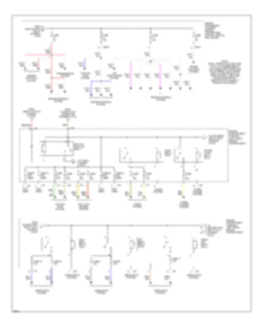
Power Distribution Wiring Diagram (2 of 6) for Jaguar XK8 1997
List of elements for Power Distribution Wiring Diagram (2 of 6) for Jaguar XK8 1997:
- (headlights system)
- (horns system)
- (not used)
- (wiper/ washer system)
- Air conditioning system
- Anti-lock brakes system
- Cooling fans system
- Dip beam relay (no.5)
- Em19
- Em20
- Engine compartment fuse box (left front engine compartment)
- Engine controls system
- Engine management fuse box (engine compartment, control module enclosure)
- From ems control e relay (diagram 1 of 6)
- From inertia switch diagram (1 of 6)
- From power wash relay (n0.4) (diagram 2 of 6)
- From tunnel stud connector (diagram 1 of 6)
- Front fog relay (no.2)
- Fuse 10 (not used)
- Fuse 10a
- Fuse 17 15a
- Fuse 19 10a
- Fuse 20 (not used)
- Fuse 21 10a
- Fuse 22 (not used)
- Fuse 30a
- Fuse 5a
- Fuse 6 10a
- Fuse 8 10a
- Fuse 9 (not used)
- Headlights system
- Horn relay (no.6)
- Horns system
- Ignition positive relay
- Lf5
- Lf6
- Lf7
- Lf70
- Lf8
- Main beam relay (no.3)
- Note: early production vehicles with vin numbers below (vin 003300) use connector pin numbers, which differ from volume production models shown. use wire color code for pin identification on early production models.
- Power- wash relay (no.4)
- To fuse 3 diagram (3 of 6)
- To heater pump relay (no.1) (diagram 3 of 6)
- To main beam relay (no.3) (diagram 2 of 6)
- Transmissions system
- Wiper/ washer system
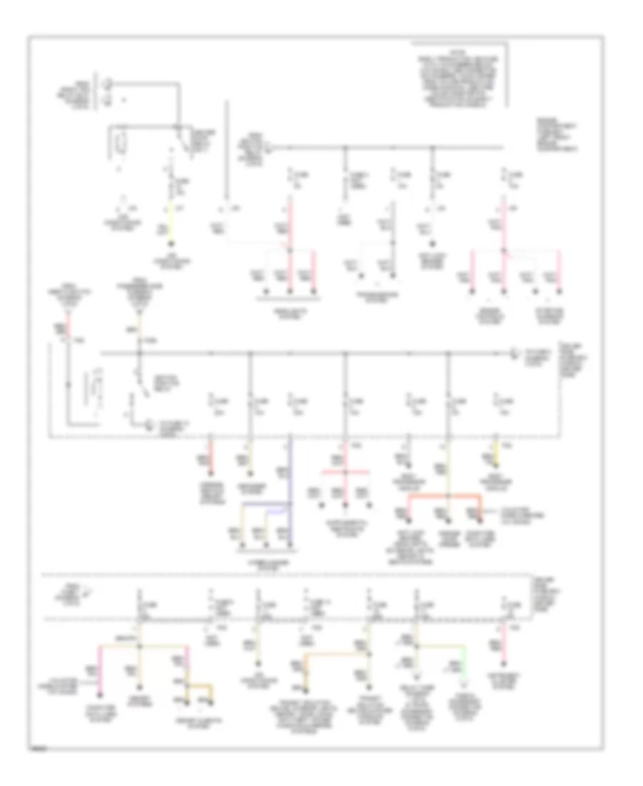
Power Distribution Wiring Diagram (3 of 6) for Jaguar XK8 1997
List of elements for Power Distribution Wiring Diagram (3 of 6) for Jaguar XK8 1997:
- (air conditioning system)
- (not used)
- (valid for models after vin: 003300)
- (valid for models before vin: 003300)
- Air conditioning system
- Anti-lock brakes system
- Anti-lock brakes, headlights, exterior lights, memory & seats systems
- Body processor module
- Computer data lines system
- Defogger system
- Delay timer (diagram 1 of 6) & trunk accessory connector (diagram 6 of 6)
- Driver side fuse box (fascia, driver side)
- Engine compartment fuse box (left front engine compartment)
- Engine controls system
- Fascia accessory connector (diagram 6 of 6)
- Fc5
- Fc6
- Fc92
- From front fog relay (n0.2) (diagram 2 of 6)
- From fuse 7 r (diagram 3 of 6)
- From ignition positive relay (diagram 2 of 6)
- From inertia switch (diagram 1 of 6)
- From passenger side fuse box (diagram 4 of 6)
- Fuse 10a
- Fuse 13 (not used)
- Fuse 15a
- Fuse 2 (not used)
- Fuse 20a
- Fuse 25a
- Fuse 30a
- Fuse 5a
- Fuse 9 (not used)
- Garage door opener
- Headlights system
- Heater pump relay (no.1)
- Ignition positive relay
- Instrument cluster system
- Lf5
- Lf6
- Lf7
- Lf8
- Memory & seats system
- Memory systems
- Mirrors, seats & memory systems
- Note: early production vehicles with vin numbers below (vin 003300) use connector pin numbers, which differ from volume production models shown. use wire color code for pin identification on early production models.
- Starting/ charging system
- To fuse 10 (diagram 4 of 6)
- To fuse 8 (diagram 3 of 6)
- Transit isolation device & power windows system
- Transit isolation device, interior lights, memory, door locks, anti-theft, power windows & mirrors systems
- Transmissions system
- Wiper/washer system
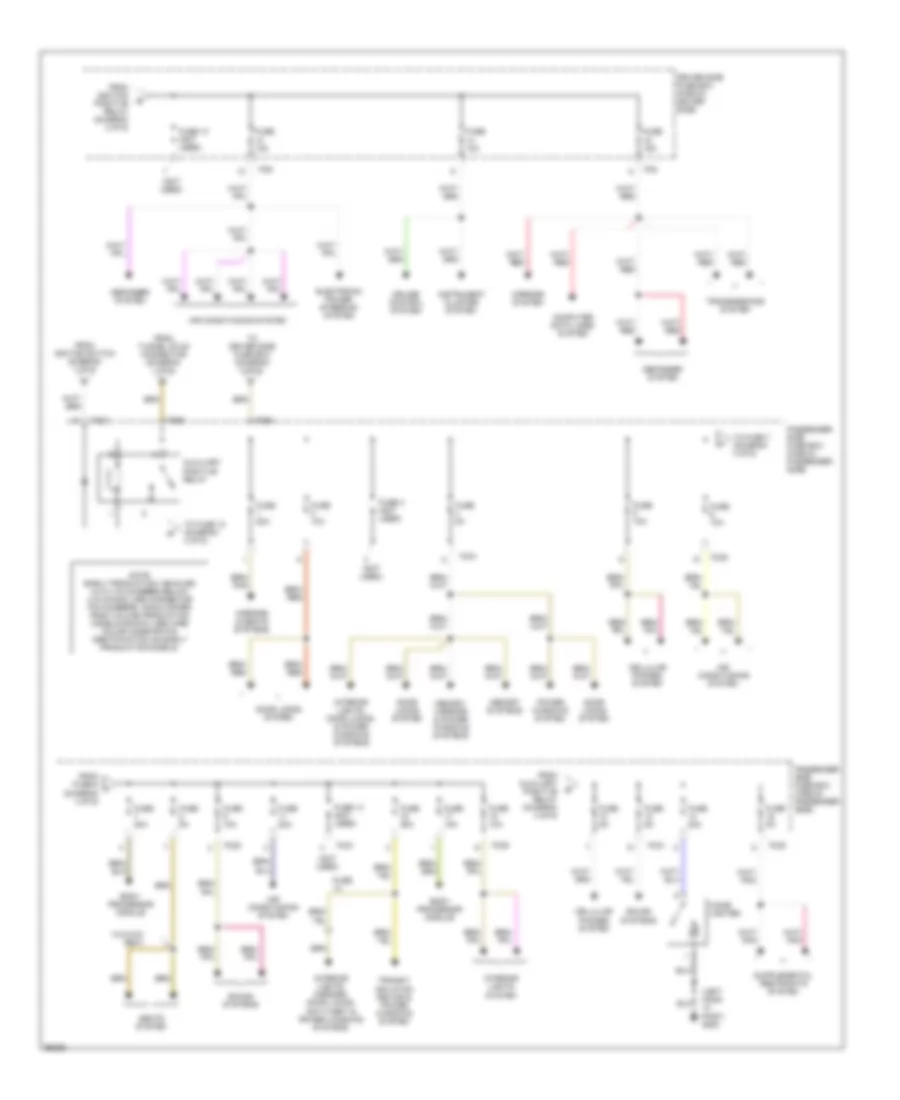
Power Distribution Wiring Diagram (4 of 6) for Jaguar XK8 1997
List of elements for Power Distribution Wiring Diagram (4 of 6) for Jaguar XK8 1997:
- (left hand "a" post) g202
- (not used)
- Air conditioning system
- Auxiliary positive relay
- Body processor module
- Cellular phones system
- Cigar lighter
- Computer data lines system
- Cruise control system
- Defogger system
- Door locks system
- Driver side fuse box (fascia, driver side)
- Electronic power steering system
- Fc20
- Fc21
- Fc5
- Fc6
- Fc90
- Fc93
- From auxiliary positive relay (diagram 4 of 6)
- From fuse 6 t (diagram 4 of 6)
- From ignition positive relay (diagram 3 of 6)
- From ignition switch (diagram 1 of 6)
- From tunnel stud connector (diagram 1 of 6)
- Fuse
- Fuse 10 (not used)
- Fuse 10a
- Fuse 13 (not used)
- Fuse 15a
- Fuse 20a
- Fuse 25a
- Fuse 3 (not used)
- Fuse 5a
- Instrument cluster system
- Interior lights system
- Interior lights, door locks, & power windows systems
- Interior lights, mirrors, door locks, anti-theft & power windows systems
- Memory systems
- Memory, mirrors & power windows systems
- Mirrors & seats systems
- Mirrors system
- Note: early production vehicles with vin numbers below (vin 003300) use connector pin numbers, which differ from volume production models shown. use wire color code for pin identification on early production models.
- Passenger side fuse box (fascia, passenger side)
- Passenger side fuse box (fascia, passenger side)
- Power windows system
- Seats system
- Sound systems
- To driver side fuse box (diagram 3 of 6)
- To fuse 10 (diagram 4 of 6)
- To fuse 7 (diagram 4 of 6)
- Transit isolation device & power windows system
- Transmissions system
- W/3-way seat
Power Distribution Wiring Diagram (5 of 6) for Jaguar XK8 1997
List of elements for Power Distribution Wiring Diagram (5 of 6) for Jaguar XK8 1997:
- (exterior lights system)
- (not used)
- Bt10
- Bt11
- Bt12
- Bt13
- Bt64
- Convertible
- Coupe
- Door locks & anti-theft systems
- Electronic suspension system
- Exterior lights system
- Exterior lights, mirrors & power tops systems
- From fuse 16 (diagram 5 of 6)
- From high power protection module (diagram 1 of 6)
- From inertia switch diagram (1 of 6)
- Fuse (not used)
- Fuse 10a
- Fuse 20a
- Fuse 20a (conv.)
- Fuse 40a (conv.)
- Fuse 5a
- Ignition positive relay
- Note: early production vehicles with vin numbers below (vin 003300) use connector pin numbers, which differ from volume production models shown. use wire color code for pin identification on early production models.
- Power antenna system
- Power tops system
- Red/ pnk
- Sound systems
- Stop lamp relay (no.5)
- Tail lamp relay (no.3)
- To fuse 3 diagram (6 of 6)
- To fuse no. 18 (diagram 5 of 6)
- To rear fog relay (no.1) (diagram 6 of 6)
- Trunk fuse box (trunk, electrical carrier)
Power Distribution Wiring Diagram (6 of 6) for Jaguar XK8 1997
List of elements for Power Distribution Wiring Diagram (6 of 6) for Jaguar XK8 1997:
- (defogger system)
- (engine controls system)
- (exterior lights system)
- (no.5) (diagram 5 of 6)
- (not used)
- (right hand "a" post g201
- (trunk, right rear) g405
- Accessory connector relay (no.6)
- Bt10
- Bt11
- Bt12
- Bt13
- Defogger system
- Electronic suspension system
- Engine controls system
- Exterior lights system
- Fascia accessory connector (adjacent to right hand side of glove box)
- From driver side fuse box (fuse 17, 10a) (diagram 3 of 6)
- From heated backlight relay x (no.2) (diagram 6 of 6)
- From heated backlight y relay (no.2) (diagram 6 of 6)
- From ignition positive u
- From ignition switch (diagram 1 of 6)
- From tail lamp relay w
- Fuel pump relay (no.4)
- Fuse (not used)
- Fuse 10a
- Fuse 20a
- Fuse 25a
- Fuse 5a
- Heated backlight relay (no.2)
- Note: early production vehicles with vin numbers below (vin 003300) use connector pin numbers, which differ from volume production models shown. use wire color code for pin identification on early production models.
- Rear fog relay (no.1)
- Relay (diagram 5 of 6)
- To auxiliary connector relay (no.6) (diagram 6 of 6)
- To fuel pump relay (no.4) (diagram 6 of 6)
- Trunk accessory connector (in trunk, adjacent to battery)
- Trunk fuse box (trunk, electrical carrier)

 Čeština
 Dansk
Dansk Deutsch
 Ελληνικά
 English
 Español
 Suomi
Suomi Français
 Français
 עברית
עברית Hrvatski
 Magyar
 Italiano
 日本語
日本語 한국어
한국어 Nederlands
 Polski
 Português
 Português
 Română
 Русский
 Slovenčina
 Slovenščina
 Svenska
 Türkçe
 中文 (中国)