TRANSMISSION
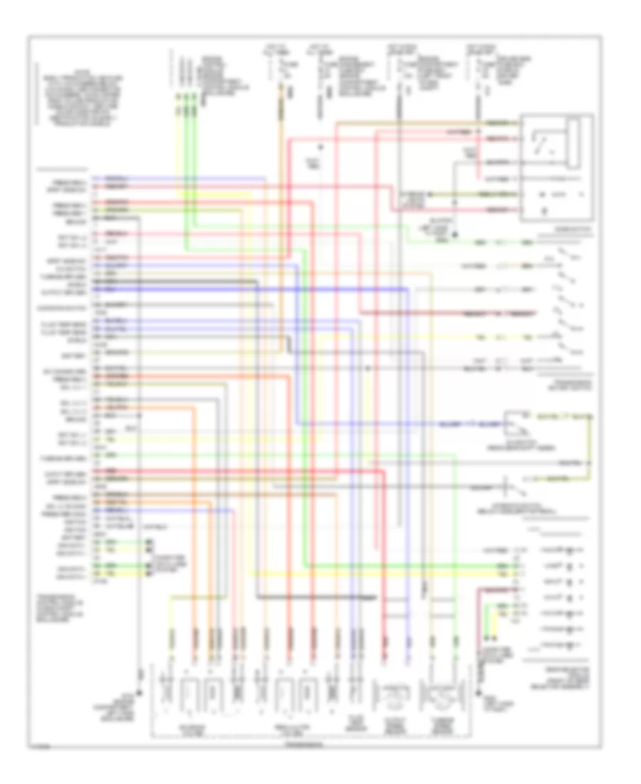
A/T Wiring Diagram for Jaguar XK8 1997
List of elements for A/T Wiring Diagram for Jaguar XK8 1997:
- (left hand "a" post) g202
- 10-11
- 19-20
- 24-25
- 38-41
- 46-50
- 56-81
- 87-88
- Battery
- Can data +
- Can data -
- Computer data lines system
- D-4 switch
- D-4 switch (rear gear shift assem)
- Driver side fuse box (fascia, driver side)
- Em20
- Enclosure) em10
- Engine compartment fuse box (left front of eng compt)
- Engine control module (engine compartment, control module p, n sig
- Engine management fuse box (engine compartment, control module enclosure)
- Fc5
- Fluid temp sens
- Fluid temp sensor
- Fuse 10a
- Fuse 5a
- G104 (engine compartment, left hand enclosure)
- G202 (left hand "a" post)
- Gear selector module (front of gear selector assembly)
- Ground
- Hot at all times
- Hot in run or start
- Ignition
- Interior lights system
- Kickdown switch
- Kickdown switch (below accelerator pedal)
- Lfb
- Mode switch
- Nca
- Note: early production vehicles with vin numbers below (vin 003300) use connector pin numbers, which differ from volume production models shown. use wire color code for pin identification on early production models.
- Ouput spd sen
- Output spd sen
- Output speed sensor
- P,n
- Press reg 1
- Press reg 2
- Press reg 3
- Press reg 4
- Press reg 5
- Press reg comm
- Red
- Red/pnk
- Regulaltor valves
- Rot sw l1
- Rot sw l2
- Rot sw l3
- Rot sw l4
- Shield
- Sol vlv 1
- Sol vlv 2
- Sol vlv 3
- Sol vlvs comm
- Solenoid valves
- Sprt mode sw
- Sw common grd
- Transmission
- Transmission control module (in eng compt control module enclosure)
- Transmission rotary switch
- Turbine spd sen
- Turbine speed sensor
 Čeština
 Dansk
Dansk Deutsch
 Ελληνικά
 English
 English
 Español
 Suomi
Suomi Français
 Français
 עברית
עברית Hrvatski
 Magyar
 Italiano
 日本語
日本語 한국어
한국어 Nederlands
 Português
 Português
 Română
 Русский
 Slovenčina
 Slovenščina
 Svenska
 Türkçe
 中文 (中国)
 Polski