СИСТЕМА УПРАВЛЕНИЯ ДВИГАТЕЛЯ
4.1L
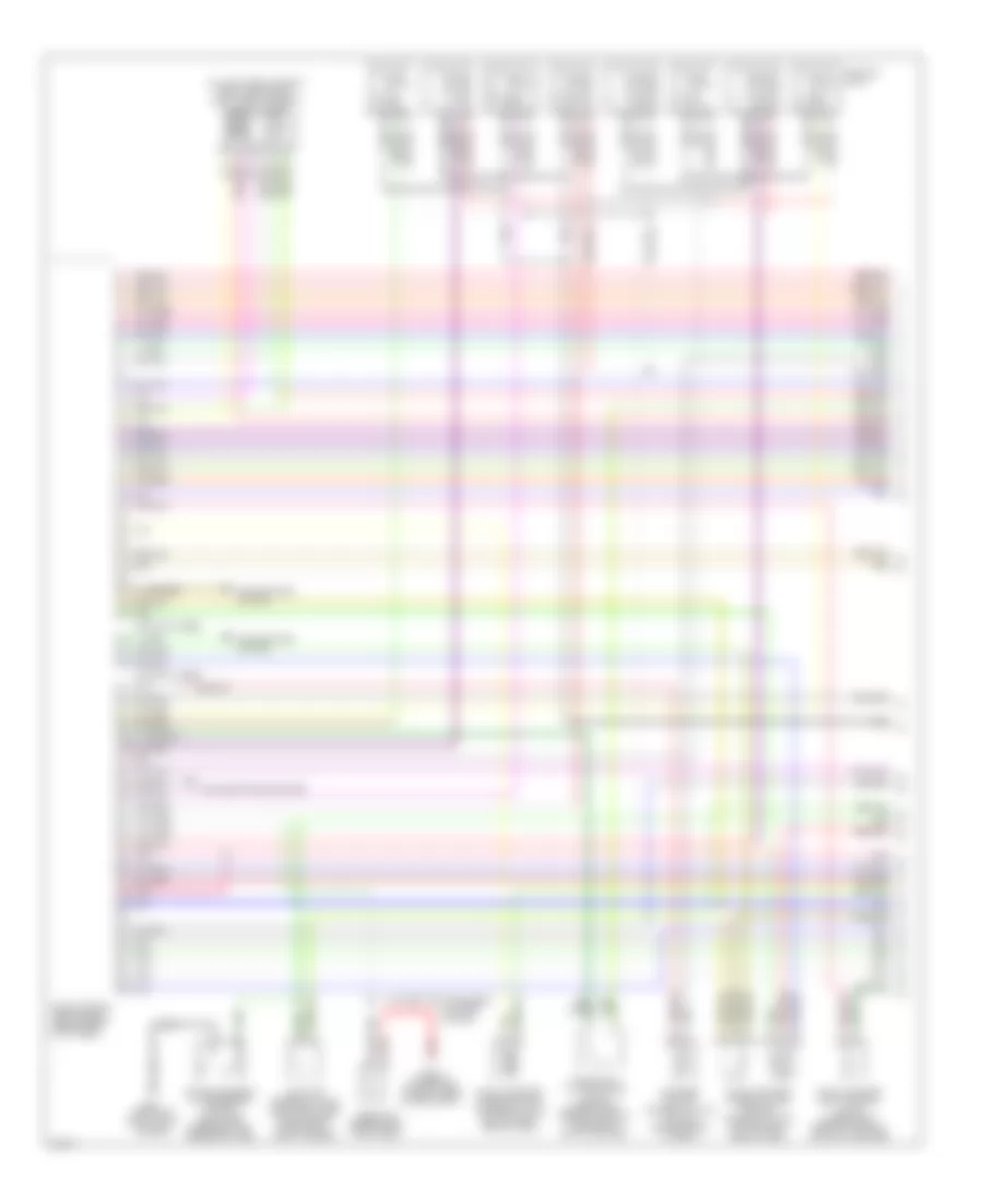
4.1L, Электросхема системы управления двигателя (1 из 4) для Infiniti Q45 t 2001
4.1L, Электросхема системы управления двигателя (1 из 4) для Infiniti Q45 t 2001 - Список элементов:
- (30-33 not used)
- (37-40 not used)
- (front of right front fender)
- (on left front side of eng, forward of left throttle body) iacv-aac valve
- Air conditioning system
- Check connector (in right rear of eng compt)
- Cooling fans system
- Eccs control module (ecm) (behind right kick panel)
- Evap canister purge control solenoid valve (on top right rear of eng)
- Evap canister purge volume control solenoid valve (on top right rear of eng)
- Evap canister vent control valve (under right rear of vehicle, on evap canister)
- G101
- Iacv-ficd solenoid valve (left front side of eng compt, forward of throttle body)
- Ignition coils
- Instrument cluster system
- Map/baro switch solenoid valve (on top center rear of eng)
- Pnk
- Power steering oil pressure switch (on power steering high pressure tube)
- Red
- Resistor (behind right kick panel)
- Vacuum cut valve bypass valve (under right rear of vehicle, forward of evap canister)
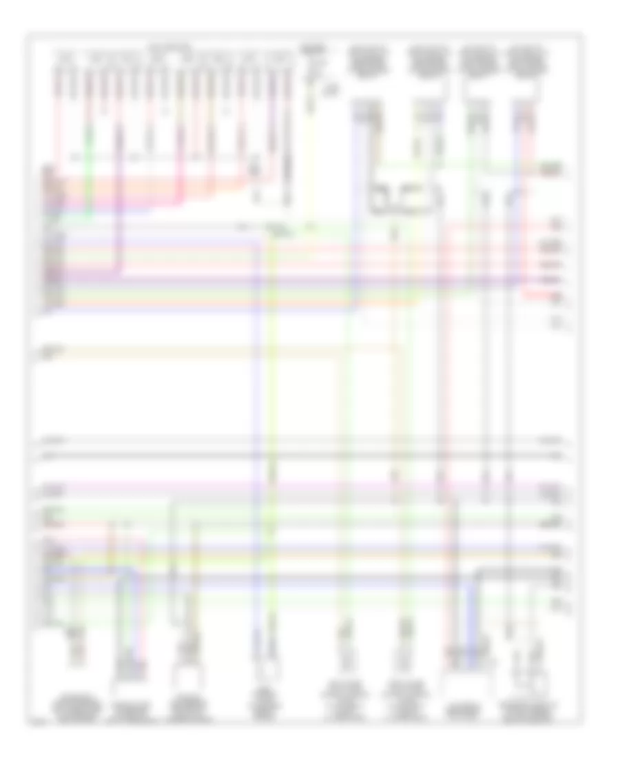
4.1L, Электросхема системы управления двигателя (2 из 4) для Infiniti Q45 t 2001
4.1L, Электросхема системы управления двигателя (2 из 4) для Infiniti Q45 t 2001 - Список элементов:
- tac module (behind right kick panel)
- (on inlet of left catalytic converter) front heated oxygen sensor (bank 1)
- (on inlet of right catalytic converter) front heated oxygen sensor (bank 2)
- (on outlet of left catalytic converter) rear heated oxygen sensor (bank 1)
- (on outlet of right catalytic converter) rear heated oxygen sensor (bank 2)
- Camshaft posi- tion sensor (on front of left cylinder head)
- Crankshaft position sensor (bottom right side of transmission bellhousing)
- Egrc solenoid valve (top center rear of engine)
- F75
- Fuel injectors
- Fuse 10a
- Fuse block
- Hot in on or start
- Left intake valve timing control solenoid valve (on top front of left cylinder head)
- Mass air- flow sensor (between air duct & air cleaner housing)
- Nca
- Pnk
- Red
- Right intake valve timing control solenoid valve (on top front of right cylinder head)
- Secondary throttle position sensor (on throttle body, next to air duct)
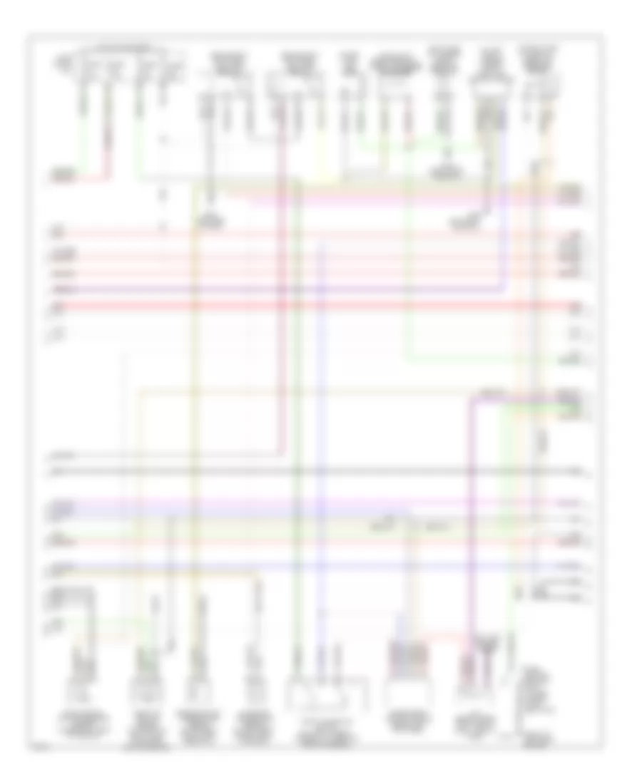
4.1L, Электросхема системы управления двигателя (3 из 4) для Infiniti Q45 t 2001
4.1L, Электросхема системы управления двигателя (3 из 4) для Infiniti Q45 t 2001 - Список элементов:
- (above left rear wheelwell, taped to harness) condenser
- (behind right kick panel) fuel pump relay-1
- (behind right kick panel) fuel pump relay-2
- (front of left front fender)
- (in fuel tank) fuel pump
- (on left side of luggage compt) fuel pump control module
- (on right side of firewall) absolute pressure sensor
- (right side of luggage compt) dropping resistor
- 12g
- 15b
- Anti-lock brakes system
- Engine coolant temperature sensor (on top right fonr of eng, near inj 2)
- Evap control system pressure sensor (under right rear of vehicle)
- Fuse 10a
- Fuse 15a
- Fuse 7.5a
- Fuse block (j/b)
- G100
- G202 (left side of dash)
- G309 (left front door sill)
- G316 (right front door sill)
- Hot in on or start
- Intake air temperature sensor (on left front of eng compt, in air duct)
- J/c 6 (behind upper right side of dash, tape to harn)
- Nca
- Park/ neutral position relay (in fuse, fusible link & relay box)
- Red
- Throttle position sensor (on throttle body, near intake mani- fold collector)
- Throttle position switch (on throttle body, integral to throttle position sensor)
- Transmission control module (behind left kick panel)
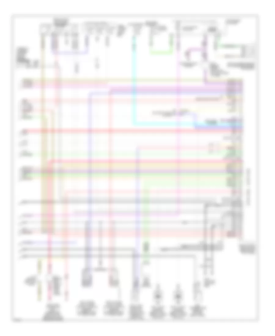
4.1L, Электросхема системы управления двигателя (4 из 4) для Infiniti Q45 t 2001
4.1L, Электросхема системы управления двигателя (4 из 4) для Infiniti Q45 t 2001 - Список элементов:
- (104 not used)
- (107 not used)
- (109-120 not used)
- (84-88 not used)
- (94-95 not used)
- (behind right kick panel) eccs relay
- (taped to harness, on right side of engine) condenser
- Air conditioning system
- Data link connector (dlc) (under left side of dash, near hood lock release handle)
- Defogger system
- Eccs control module (ecm) (behind right kick panel)
- Egr temperature sensor (top left rear of eng)
- Fuel tank gauge unit (tank fuel temperature sensor) (in fuel tank)
- Fuse 10a
- Fuse 15a
- Fuse 7.5a
- Fuse block
- Fuse, fusible link & relay box
- G110 (top left front of eng)
- Headlights system
- Hot at all times
- Hot in on or start
- Hot in start
- Instrument cluster
- J/c 2 (behind left side of dash, near fuse block)
- J/c 6 (behind upper right side of dash, taped to harn)
- J/c 8 (behind left kick panel)
- Left intake valve timing control position sensor (on rear of left cylinder head)
- Left knock sensor (below left side of intake manifold)
- Malfunction ind lamp
- Nats immu (near ashtray)
- Nca
- Pnk
- Red
- Right intake valve timing control position sensor (on rear of right cylinder head)
- Right knock sensor (below right side of intake manifold)
- Speedo- meter
- Transmissions system
- Vehicle speed sensor (on transmission rear extension)

 Čeština
 Dansk
Dansk Deutsch
 Ελληνικά
 English
 English
 Español
 Français
 Français
 עברית
עברית Hrvatski
 Magyar
 Italiano
 日本語
日本語 한국어
한국어 Nederlands
 Polski
 Português
 Português
 Română
 Русский
 Slovenčina
 Slovenščina
 Svenska
 Türkçe
 中文 (中国)