AIR CONDITIONING
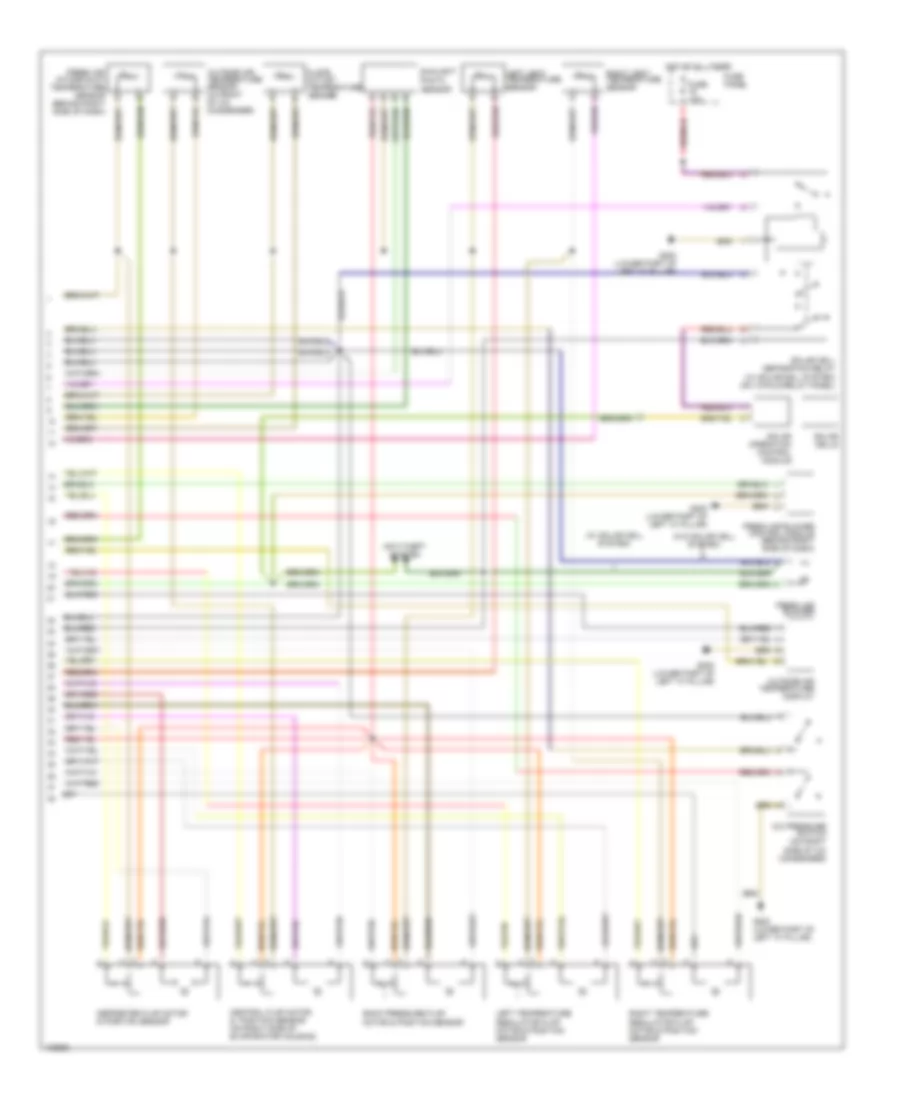
Automatic A/C Wiring Diagram (1 of 2) for Audi A6 1998

List of elements for Automatic A/C Wiring Diagram (1 of 2) for Audi A6 1998:
- 8-fold relay panel
- A/c clutch
- A/c control head
- Air quality sensor
- Anti-lock brakes system
- Coolant fan
- Coolant fan control relay (on 8-fold relay panel)
- Coolant fan control series resistor (behind left side of front bumper, on chassis member)
- Coolant fan control thermal switch (on lower right side of radiator)
- Data link connector (below left side of dash)
- Defogger system
- Fuse 10a
- Fuse 30a
- Fuse 40a
- Fuse 5a
- Fuse panel
- G200 (lower left "a" pillar)
- G200 g200 (lower left (lower left "a" pillar) "a" pillar)
- Hot at all times
- Hot in run
- Hot w/ load reduction relay energized
- Instrument cluster
- Interior lights system
- Motronic engine control module (in elect box, left side of fresh air plenum)
- Second speed coolant fan control relay (on 8-fold relay panel)
- T32
- T32a
- Tachometer
- Wiper/washer system
Automatic A/C Wiring Diagram (2 of 2) for Audi A6 1998
List of elements for Automatic A/C Wiring Diagram (2 of 2) for Audi A6 1998:
- (w/ solar cell system)
- (w/o solar cell system)
- A/c pressure switch (on right side of a/c condenser)
- Anti-theft system
- Back pressure flap motor & position sensor
- Central flap motor & position sensor (on right side of evaporator housing)
- Defroster flap motor & position sensor
- Floor outlet temperature sender
- Fresh air blower
- Fresh air blower control module (behind right side of dash)
- Fresh air intake duct temperature sensor (behind right side of dash)
- Fuse 10a
- Fuse panel
- G200 (lower part of left "a" pillar)
- Hot at all times
- Left temperature regulator flap motor & position sensor
- Left vent temperature sensor
- Outside air temperature display
- Outside air temperature sensor (in front of a/c condenser)
- Right temperature regulator flap motor & position sensor
- Right vent temperature sensor
- Sensor
- Solar cell separation relay (w/ solar cell system) (on 13-fold relay panel)
- Solar cells
- Solar operation control module
- Sunlight photo