POWER DISTRIBUTION
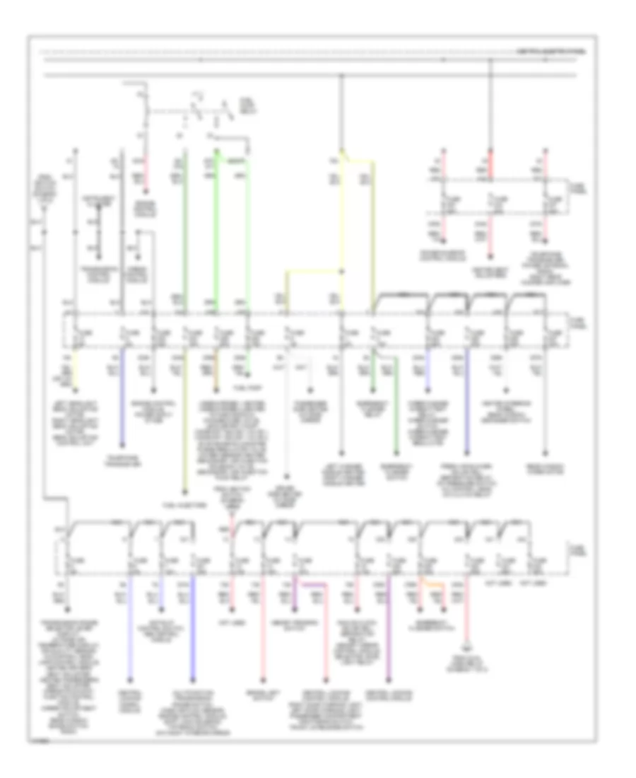
Power Distribution Wiring Diagram (1 of 3) for Audi A6 1998

List of elements for Power Distribution Wiring Diagram (1 of 3) for Audi A6 1998:
- (not used)
- 18a
- 19a
- 20a
- 21a
- 223a
- 22a
- 233a
- 236a
- 50b
- 86s
- A/c control head
- Acc
- Battery
- Central electric panel
- Central locking control module
- Cigarette lighter
- Dual horn relay
- Fog light relay
- Fog light switch
- Fuse 10a
- Fuse 15a
- Fuse 5a
- Fuse panel
- G900 (lower left "a" pillar)
- Generator, instrument cluster
- Headlight dimmer/ flasher switch
- Headlight high beam indicator light
- Horn button
- Ignition switch
- Instrument cluster
- Instrument cluster, central locking control module
- Interior lights system
- Key-in ignition switch
- Lamp control module
- Left high beam headlight
- License plate
- Light light switch switch
- Load reduction relay
- Low tone relay, high tone relay
- Off
- Protection diode, glove compartment light
- Rear cigarette lighter
- Red
- Right high beam headlight
- Right parking light
- Run
- S1/
- S1/ 30ah
- S2/ 87h
- Start
- Starter
- Starting interlock relay
- To fuse 12 (diagram 2 of 3)
- To fuse 240 (diagram 2 of 3)
- To fuse 5 (diagram 2 of 3)
- Voltage regulator/ generator
- Wiper/washer intermittent relay
Power Distribution Wiring Diagram (2 of 3) for Audi A6 1998
List of elements for Power Distribution Wiring Diagram (2 of 3) for Audi A6 1998:
- 10a
- 12a
- 13a
- 14a
- 15a
- 224a
- 225a
- 226a
- 227a
- 228a
- 229a
- 230a
- 231a
- 232a
- 234a
- 237a
- 238a
- 239a
- 240a
- 244a
- 75x
- 87f/ dti
- Airbag control module
- Analog clock, solar cell separation relay, memory mirror control module, selector level light relay
- Anti-slip control switch, abs control module
- Brake light switch
- Central electric panel
- Central locking conrol module
- Central locking control module
- Central locking control module, right door warning light, left door warning light, passenger compartment monitoring switch, trunk lid release switch
- Driver side heated outside mirror
- Emergency flasher relay
- Emergency flasher switch
- Engine control module
- Engine control module, power ouput stage
- Fresh air blower, solar cell separation relay, a/c pressure switch, a/c control head, a/c clutch relay
- From dual horn relay (diagram 1 of 2)
- From ignition switch (diagram 1 of 3)
- Fuel injectors
- Fuel pump
- Fuel pump relay
- Fuse 10a
- Fuse 15a
- Fuse 20a
- Fuse 25a
- Fuse 30a
- Fuse 5a
- Fuse 60a
- Fuse panel
- Heated seat adjusters
- Heated steering wheel, rear window defogger switch
- Instrument cluster
- Lambda-probe 1 heater, lambda-probe 2 heater, intake manifold change-over valve, leak detect pump, camshaft adjust valve 1, camshaft adjust valve 2, evap emission canister purge regulator valve, oxygen sensor heater, secondary air injection solenoid valve, secondary air injection pump relay
- Left headlight beam adjusting motor, right headlight beam adjusting motor, beam adjusting control unit
- Left washer nozzle heater, right washer nozzle heater
- Memory program switch
- Multifunction transmissiom range switch, mass air flow sensor, engine control module, shift lock solenoid, tiptronic switch, day/night interior mirror
- Nca
- Not used
- Passenger side heated outside mirror
- Power sunroof control module
- Rear window wiper motor
- Red
- S2/87f
- S3/
- S3/ 87a
- S3/s
- Telephone transceiver
- Telephone transceiver, power antenna, radio, right rear woofer amplifier
- Transmission control module
- Transmission range selector lever display, outside air temperature display, air quality sensor, a/c control head, lamp control module, heated driver's seat adjuster, heated passenger's seat adjuster, mirror fold-away function control module, mirror adjustment switch, rear window shade switch, radio
- Wiper/washer intermittent relay, wiper/washer switch, wiper/washer intermittent regulator
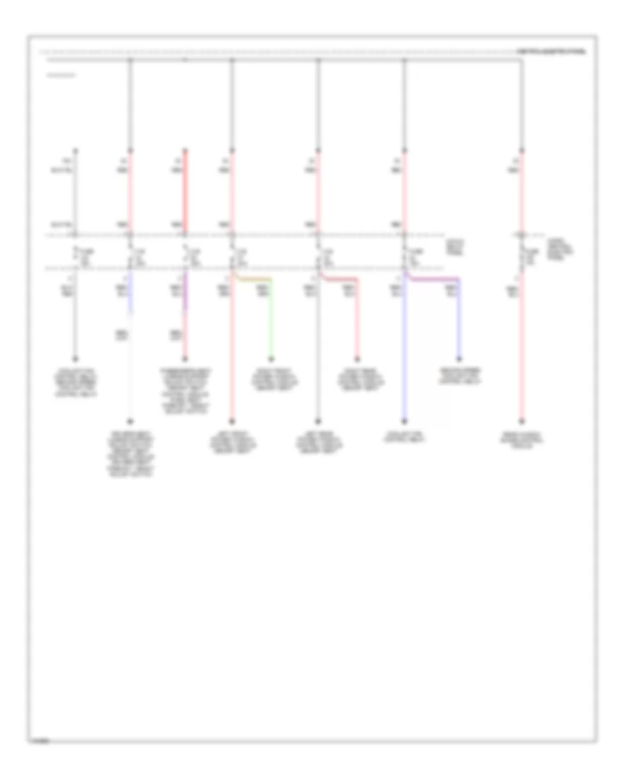
Power Distribution Wiring Diagram (3 of 3) for Audi A6 1998
List of elements for Power Distribution Wiring Diagram (3 of 3) for Audi A6 1998:
- 75x
- 8-fold relay panel
- C.b. 30a
- Central electric panel
- Coolant fan control relay
- Coolant fan control relay, second speed coolant fan control relay
- Driver's seat lumbar support adjust switch, memory seat control module, driver's seat fore/aft height adjust switch
- Fuse 10a
- Fuse 15a
- Left front power window control module memory seat
- Left rear power window control module memory seat
- Micro- central electric panel
- Passenger's seat lumbar support adjust switch, memory seat control module, pass. seat fore/aft height adjust switch
- Rear window shade control module
- Red
- Right front power window control module memory seat
- Right rear power window control module memory seat
- Second speed coolant fan control relay