AIR CONDITIONING
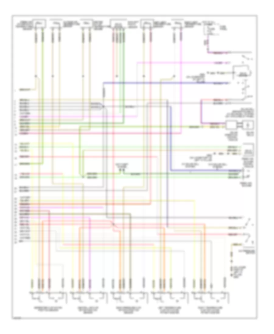
Automatic A/C Wiring Diagram, with Coolant Fan Control Module (1 of 2) for Audi allroad Quattro 2001

List of elements for Automatic A/C Wiring Diagram, with Coolant Fan Control Module (1 of 2) for Audi allroad Quattro 2001:
- (dlc) (partial) (below left side of dash)
- 8-fold relay panel
- A/c clutch
- A/c clutch relay (on 13-fold relay panel)
- A/c control module
- A10
- A11
- A12
- After-run coolant pump (2.7l, 2.8l)
- After-run coolant thermal switch (2.7l)
- Air quality sensor
- Anti-lock brakes system
- B10
- B11
- B12
- B13
- B14
- B15
- B16
- B17
- B18
- B19
- B20
- C10
- C11
- C12
- C13
- C14
- C15
- C16
- Coolant fan
- Coolant fan 2
- Coolant fan control (fc) thermal switch
- Coolant fc (fan control) control module
- D10
- D11
- D12
- D13
- D14
- D15
- D16
- Data link connector
- Defogger system
- Except 2.8l w/ front wheel drive
- Fuse 10a
- Fuse 30a
- Fuse 5a
- Fuse 60a
- Fuse panel
- G104 (left rear of engine compt)
- G900 (on lower left part of "a" pillar)
- Hot at all times
- Hot in run or start
- Hot in start
- Hot w/ load reduction relay energized
- Instrument cluster
- Interior lights system
- Motronic engine control module (ecm)
- Of "a" pillar) g900
- Solid state
- T32
- T32a
- Tachometer
- Wiper/washer system
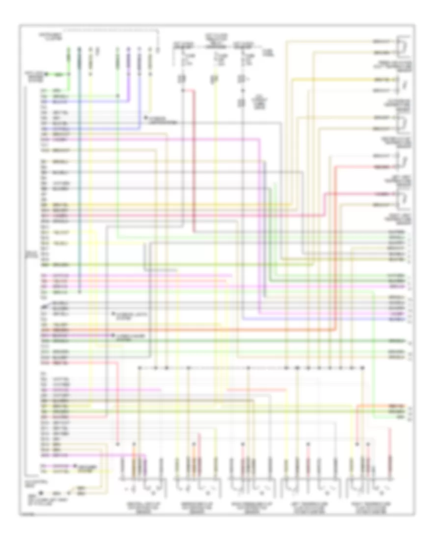
Automatic A/C Wiring Diagram, with Coolant Fan Control Module (2 of 2) for Audi allroad Quattro 2001
List of elements for Automatic A/C Wiring Diagram, with Coolant Fan Control Module (2 of 2) for Audi allroad Quattro 2001:
- (on lower part of left "a" pillar) g900
- (w/ solar cell system)
- (w/o solar cell system)
- A/c pressure switch
- Anti-theft system
- Back pressure flap motor & position sensor
- Center outlet temperature sender
- Central air flap motor position sensor
- Defroster flap motor/ position sensor
- Fresh air blower
- Fresh air blower control module
- Fresh air intake duct temperature sensor
- Fuse 10a
- Fuse panel
- G900 (on lower part of left "a" pillar)
- Hot at all times
- Left temperature flap actuator/ potentiometer
- Left vent temperature sensor
- Outside air temperature sensor
- Right temperature flap actuator/ potentiometer
- Right vent temperature sensor
- Sensor
- Solar cell separation relay (w/ solar cell system) (on 13-fold relay panel)
- Solar cells
- Solar operation control module
- Solid state
- Sunlight photo
Automatic A/C Wiring Diagram, without Coolant Fan Control Module (1 of 2) for Audi allroad Quattro 2001
List of elements for Automatic A/C Wiring Diagram, without Coolant Fan Control Module (1 of 2) for Audi allroad Quattro 2001:
- 2.8l w/front wheel drive
- A/c control head
- A10
- A11
- A12
- Anti-lock brakes system
- B10
- B11
- B12
- B13
- B14
- B15
- B16
- B17
- B18
- B19
- B20
- Back pressure flap motor position sensor
- C10
- C11
- C12
- C13
- C14
- C15
- C16
- Center outlet temperature sensor
- Central air flap motor position sensor
- D10
- D11
- D12
- D13
- D14
- D15
- D16
- Defogger system
- Defroster flap motor/position sensor
- Fresh air intake duct temperature sensor
- Fuse 10a
- Fuse 15a
- Fuse 30a
- Fuse panel
- G900 (on lower left part of "a" pillar)
- Hot in run or start
- Hot w/load reduction relay energized
- Instrument cluster
- Interior lights system
- Interior lights system
- Left temperature flap actuator/ potentiometer
- Left vent temperature sensor
- Outside air temperature sensor
- Right temperature flap actuator/ potentiometer
- Right vent temperature sensor
- Solid state
- T32
- T32a
- Wiper/washer system
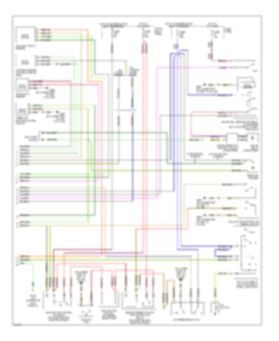
Automatic A/C Wiring Diagram, without Coolant Fan Control Module (2 of 2) for Audi allroad Quattro 2001
List of elements for Automatic A/C Wiring Diagram, without Coolant Fan Control Module (2 of 2) for Audi allroad Quattro 2001:
- (on lower part of left "a" pillar) g900
- (w/o solar cell system)
- (w/solar cell system)
- 2.8l w/front wheel drive
- 8-fold relay panel
- A/c clutch
- A/c clutch relay (on 13 fold relay panel, position 5)
- A/c pressure switch
- Air quality sensor
- All other models
- Anti-theft system
- Coolant fan
- Coolant fan control (fc) relay (on micro central electric panel)
- Coolant fan control (fc) series resistance
- Coolant fan control (fc) thermal switch
- Data link connector (dlc) (partial)
- Fresh air blower
- Fresh air blower control module
- Fuse 10a
- Fuse 30a
- Fuse 40a
- Fuse 5a
- Fuse panel
- G900 (on lower part of left "a" pillar)
- Hot at all times
- Hot w/load reduction relay energized
- Motronic engine control module (ecm)
- Nca
- Second speed coolant fan control (fc) relay (on micro central electric panel)
- Solar cell separation relay (if equipped) (on 13 fold relay panel, position 3)
- Solar cells (if equipped)
- Solar operation control module (if equipped)
- Solid state
- Sunlight photo sensor