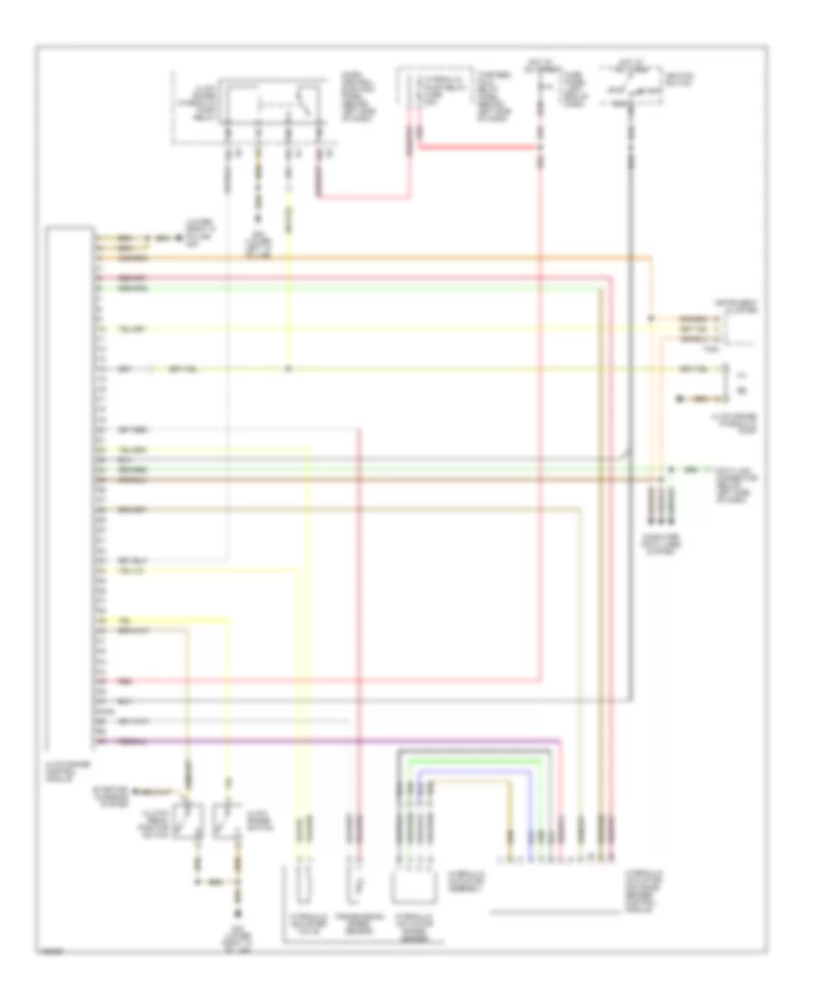
TRANSMISSION
A/T Wiring Diagram for Audi allroad Quattro 2001

List of elements for A/T Wiring Diagram for Audi allroad Quattro 2001:
- (01l trans)
- (behind left side of dash) thirteen-fold relay panel
- (lower
- 01l trans
- 11-12
- 31a
- 38-39
- 48-50
- 50b
- 56-84
- A/c system
- Anti-lock brakes system
- Brake light switch (pedal support bracket)
- Computer data lines system
- Cruise control system
- Data link connector (below left side of dash)
- Engine control module (ecm) (in electronic box, left side of fresh air plenum)
- Engine controls system
- Exterior lights system
- Exterior lights system (backup)
- Fuse 10a
- Fuse 15a
- Fuse panel (left side of dash)
- G12 (left side of engine compt)
- G44
- G44 (lower left "a" pillar)
- Hot at all times
- Ignition switch
- Instrument cluster
- Kickdown switch (on firewall)
- Left "a" pillar)
- Multifunction transmission range switch (left side of transmission)
- Off
- Pressure control valves
- Red
- Run
- Shift lock solenoid (under center console)
- Solenoid valves
- Start
- Starter terminal (50)
- Starting interlock relay
- Steering wheel controls
- T32
- T32a
- Tiptronic switch
- Transmission control module (tcm) (under right front seat)
- Transmission fluid temperature sensor
- Transmission speed sensor
- Transmission vehicle speed sensor
- Valve body
M/T Wiring Diagram, with Low Range Control Module for Audi allroad Quattro 2001
List of elements for M/T Wiring Diagram, with Low Range Control Module for Audi allroad Quattro 2001:
- (lower right "a" pillar) g43
- 4-low range control module
- 4-low range hydraulic pump
- 4-low range hydraulic pump relay
- 4-low range switch
- 48-64
- 53c
- 53e
- 75a
- Clutch pedal position switch
- Computer data lines system
- Data link connector (below left side of dash)
- Fuse panel (left end of dash)
- G43 (lower right "a" pillar)
- G44 (lower left "a" pillar)
- Hot at all times
- Hydraulic actuator assembly
- Hydraulic actuator distance sender control module
- Hydraulic actuator range sender
- Hydraulic adjuster valve
- Hydraulic pump relay fuse 20a
- Ignition switch
- Instrument cluster
- Micro central electric panel (behind left side of dash)
- Off
- Red
- Run
- Start
- Starting/ charging system
- T32a
- Thirteen fold relay panel (behind left side of dash)
- Transmission speed sensor