AIR CONDITIONING
Automatic A/C Wiring Diagram (1 of 3) for BMW 640i 2013

List of elements for Automatic A/C Wiring Diagram (1 of 3) for BMW 640i 2013:
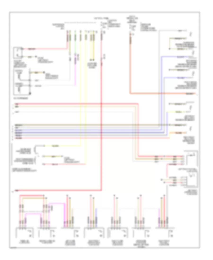
Automatic A/C Wiring Diagram (2 of 3) for BMW 640i 2013
List of elements for Automatic A/C Wiring Diagram (2 of 3) for BMW 640i 2013:
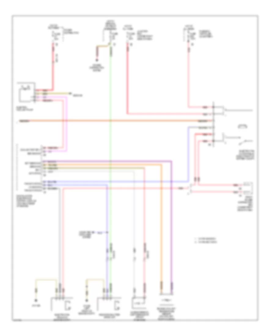
Automatic A/C Wiring Diagram (3 of 3) for BMW 640i 2013
List of elements for Automatic A/C Wiring Diagram (3 of 3) for BMW 640i 2013:
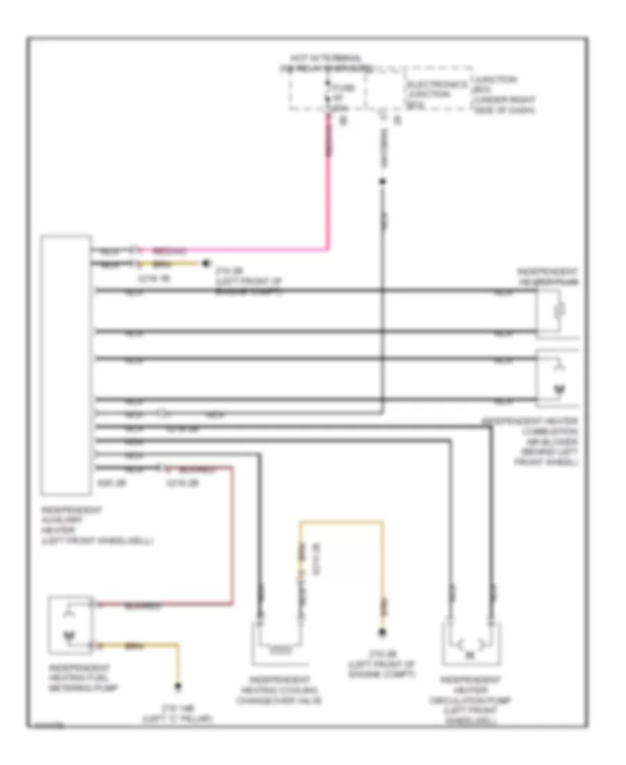
Independent Heating Wiring Diagram for BMW 640i 2013
List of elements for Independent Heating Wiring Diagram for BMW 640i 2013: