
HORN
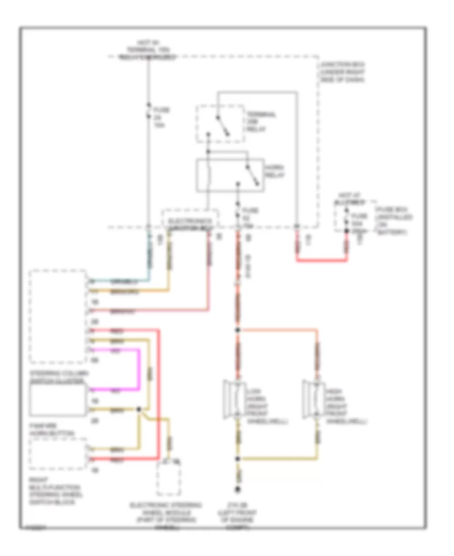
Horn Wiring Diagram for BMW 640i 2013
List of elements for Horn Wiring Diagram for BMW 640i 2013:
ANTI-LOCK BRAKESCOMPUTER DATA LINESAIR CONDITIONINGACTIVE BODYWORKSANTI-THEFTBODY CONTROL MODULESELECTRONIC POWER STEERINGCRUISE CONTROLENGINE PERFORMANCECOOLING FANGROUND DISTRIBUTIONEXTERIOR LIGHTSDEFOGGERSELECTRONIC SUSPENSIONHEADLIGHTSHORNINTERIOR LIGHTSPASSIVE RESTRAINTSPOWER DISTRIBUTIONINSTRUMENT CLUSTERMEMORY SYSTEMSNAVIGATIONPOWER MIRRORSPOWER DOOR LOCKSRADIOSTARTING/CHARGINGSHIFT INTERLOCKPOWER TOP/SUNROOFPOWER WINDOWSPOWER SEATSTRUNK, TAILGATE, FUEL DOORTRANSMISSIONSUPPLEMENTAL RESTRAINTSWARNING SYSTEMS