AIR CONDITIONING
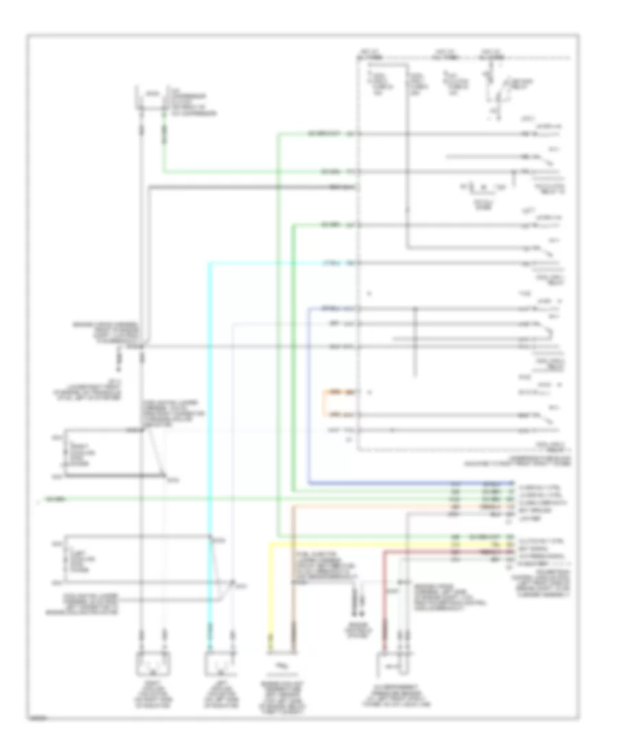
Automatic A/C Wiring Diagram (1 of 2) for Buick Century Limited 2005

List of elements for Automatic A/C Wiring Diagram (1 of 2) for Buick Century Limited 2005:
- (behind right side of dash compt) g200
- (i/p wiring harness, 18 cm from radio breakout)
- (i/p wiring harness, 4 cm left of hvac control module breakout)
- (i/p wiring harness, behind center of dash, 4 cm from radio breakout)
- (i/p wiring harness, right side of steering column, 19 cm from radio breakout)
- (lower center of dash) hvac control module
- (on right side of hvac module) vacuum control assembly
- 5 v ref
- A/c solenoid
- Air temp dr ctrl
- Ambient outside air temperature sensor (front of radiator support)
- Ambient temp sig
- Battery
- Bi-level solenoid
- Blower motor (behind right side of dash, in hvac module)
- Blower motor control processor (behind right side of dash, in hvac module)
- Blower speed ctrl
- C10
- C11
- C12
- C13
- C14
- C15
- C16
- Class 2 serial data
- Cntrl in
- D10
- D11
- D12
- D13
- D14
- D15
- D16
- Data link connector (dlc) (under left side of dash, right of steering column)
- Def mode sol ctrl
- Defogger system
- Defrost solenoid
- Gnd
- Heater solenoid
- High blower fuse 30a
- Hot at all times
- Hot in run
- Hvac fuse 10a
- I/p fuse block (behind right side of dash, in right door opening)
- Ign 3 voltage
- Inside air temperature sensor (at left side of dash, below instrument cluster)
- Inside temp sig
- Interior lights system
- Ip dim sw sig
- Left air temperature actuator (left side of hvac module)
- Low ref
- Lt temp dr pos
- Lwr mode sol ctrl
- Mix-blnd sol ctrl
- Radio, hvac, rfa, cluster aldl fuse 15a
- Recirc sol ctrl
- Recirc solenoid
- Red
- Right air temperature actuator (right side of hvac module)
- Rr defog rly ctrl
- Rt temp dr ctrl
- Rt temp dr pos
- S202
- S230
- S231 (i/p wiring harness, 33 cm from hvac control module connector)
- S233
- S258
- Solid state
- Sp205 (behind data link connector)
- Sun load sig
- Sunload sensor (on top right side of dash, near defogger outlet)
- Tan
- Upper mode sol ctrl
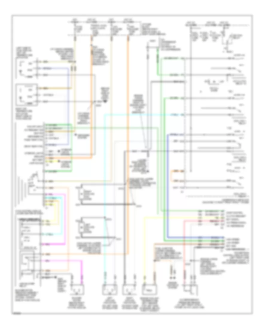
Automatic A/C Wiring Diagram (2 of 2) for Buick Century Limited 2005
List of elements for Automatic A/C Wiring Diagram (2 of 2) for Buick Century Limited 2005:
- (cooling fan jumper harness, 19.5 cm from right connector to engine cooling fan motor)
- (cooling fan jumper harness, 20 cm from left connector to engine cooling fan motor)
- (engine wiring harness, front of engine compt, 4 cm from c105 breakout) s105
- (engine wiring harness, left side of engine compt, 4 cm from powertrain control module breakout)
- (fuel injector jumper harness, midway between fuel inj no 3 breakout & map sensor breakout)
- (top left side of engine, below throttle body)
- 5 volt ref
- A/c compressor clutch (on front of a/c compressor)
- A/c clu diode
- A/c clutch fuse 23 10a
- A/c clutch relay 15
- A/c press signal
- A/c refrigerent pressure sensor (at left front strut tower, on a/c liquid line)
- A10
- A11
- C11
- Class 2 ser data
- Clutch rly ctrl
- Cool fan 1 fuse 6 25a
- Cool fan 2 fuse 24 15a
- Cool fan 1 relay
- Cool fan 2 relay
- Cool fan 3 relay
- E10
- Ect ground
- Ect signal
- Engine controls system
- Engine coolant temperature (ect) sensor
- F12
- G113 (lower right front of engine, on transaxle stud, left of starter)
- Hi spd rly ctrl
- Hot at all times
- Ign main relay
- Left cooling fan diode
- Left cooling fan motor (on left side of radiator)
- Lo spd rly ctrl
- Low ref
- Nca
- P10
- P11
- Powertrain control module (pcm) (left front side of engine compt, in air cleaner assembly)
- R10
- R11
- Right cooling fan diode
- Right cooling fan motor (on right side of radiator)
- S101
- S102
- S103
- S104
- S121
- S167
- T10
- T11
- U11
- Underhood fuse block (mounted to right front strut tower)
- V10
- V11
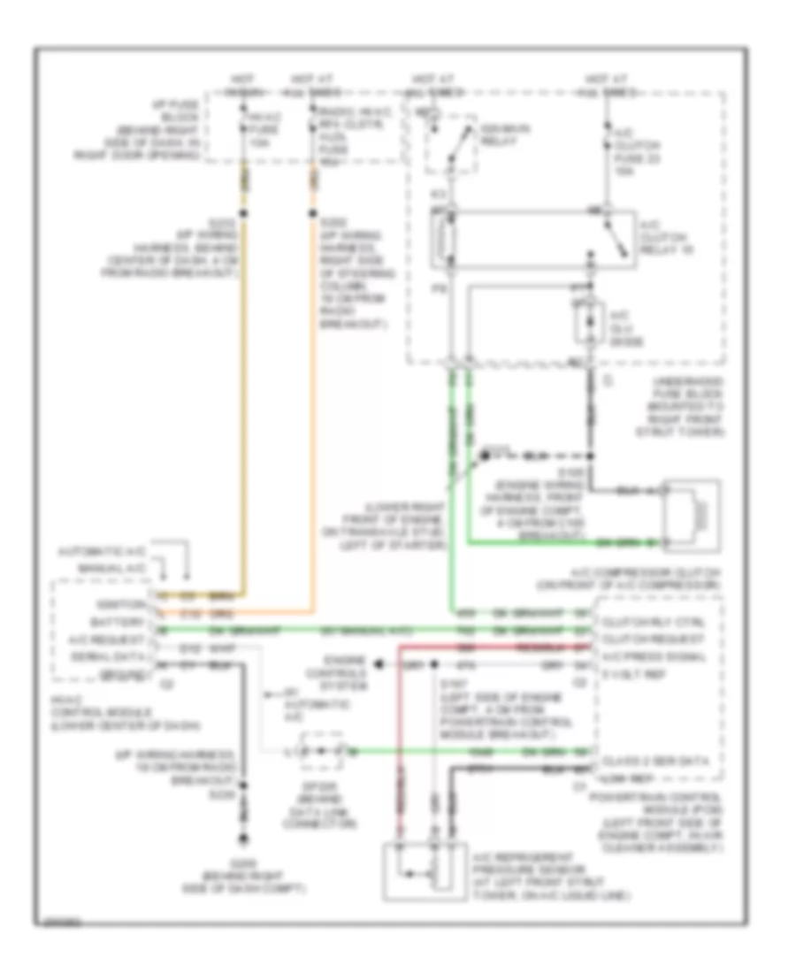
Compressor Wiring Diagram for Buick Century Limited 2005
List of elements for Compressor Wiring Diagram for Buick Century Limited 2005:
- (i/p wiring harness, 18 cm from radio breakout)
- (lower right front of engine, on transaxle stud, left of starter)
- (w/ manual a/c)
- 5 volt ref
- A/c clu diode
- A/c clutch fuse 23 10a
- A/c clutch relay 15
- A/c compressor clutch (on front of a/c compressor)
- A/c press signal
- A/c refrigerent pressure sensor (at left front strut tower, on a/c liquid line)
- A/c request
- Automatic a/c
- Battery
- C11
- C12
- Class 2 ser data
- Clutch request
- Clutch rly ctrl
- D12
- Engine controls system
- G113
- G200 (behind right side of dash compt)
- Ground
- Hot at all times
- Hot in run
- Hvac control module (lower center of dash)
- Hvac fuse 10a
- I/p fuse block (behind right side of dash, in right door opening)
- Ign main relay
- Ignition
- Low ref
- Manual a/c
- Powertrain control module (pcm) (left front side of engine compt, in air cleaner assembly)
- Radio, hvac, rfa clstr, aldl fuse 15a
- S105 (engine wiring harness, front of engine compt, 4 cm from c105 breakout)
- S167 (left side of engine compt, 4 cm from powertrain control module breakout)
- S202 (i/p wiring harness, right side of steering column, 19 cm from radio breakout)
- S230
- S233 (i/p wiring harness, behind center of dash, 4 cm from radio breakout)
- Serial data
- Sp205 (behind data link connector)
- Underhood fuse block (mounted to right front strut tower)
- W/ automatic a/c
Manual A/C Wiring Diagram for Buick Century Limited 2005
List of elements for Manual A/C Wiring Diagram for Buick Century Limited 2005:
- (behind right side of dash compt) g200
- (cooling fan jumper harness, 19.5 cm from right connector to engine cooling fan motor)
- (cooling fan jumper harness, 20 cm from left connector to engine cooling fan motor)
- (engine wiring harness, front of engine compt, 4 cm from c105 breakout)
- (engine wiring harness, left side of engine compt, 4 cm from powertrain control module breakout)
- (fuel injector jumper harness, midway between fuel inj no 3 breakout & map sensor breakout) s121
- (i/p wiring harness, 18 cm from radio breakout)
- (i/p wiring harness, behind center of dash, 4 cm from radio breakout)
- (left side of hvac module) left air temperature actuator
- (on left side of radiator)
- (on right side of radiator)
- (top left side of engine, below throttle body)
- +5v reference
- A/c compressor clutch (on front of a/c compressor)
- A/c clu diode
- A/c clutch fuse 10a
- A/c clutch relay 15
- A/c press signal
- A/c refrigerant pressure sensor (at left front strut tower, on a/c liquid line)
- A/c request sig
- A10
- A11
- Battery
- Blower motor (behind right side of dash, in hvac module)
- Blower motor resistor assembly (under right side of dash, in right side of hvac module)
- C11
- Clutch request
- Comp control
- Cool fan 1 fuse 25a
- Cool fan 2 fuse 15a
- Cool fan 1 relay
- Cool fan 2 relay
- Cool fan 3 relay
- Defogger on
- Defogger system
- Drvr temp ctrl
- E10
- Ect gnd
- Ect signal
- Engine controls system
- Engine coolant temperature (ect) sensor
- F12
- Fan off input
- G200 (behind right side of dash compt)
- Gnd
- Ground
- High blower fuse 30a
- High blower relay
- High speed
- Hot at all times
- Hot in run
- Hvac control module (lower center of dash)
- Hvac fuse 10a
- I/p fuse block (behind right side of dash, in right door opening)
- Ign
- Ign main relay
- Ignition
- Interior lights
- Interior lights system
- Lamp dim sig
- Left cooling fan diode
- Left cooling fan motor
- Low blower fuse 20a
- Low reference
- Low speed
- Nca
- Off
- P10
- P11
- Pass temp ctrl
- Pos
- Powertrain control module (pcm) (left front side of engine compt, in air cleaner assembly)
- R10
- R11
- Radio, hvac, rfa clstr, aldl fuse 15a
- Right air temperature actuator (right side of hvac module)
- Right cooling fan diode
- Right cooling fan motor
- S101
- S102
- S103
- S104
- S105
- S167
- S230
- S233
- T10
- T11
- Tan
- Thermal breakers
- U11
- Underhood fuse block (mounted to right front strut tower)
- V10
- V11