TRANSMISSION
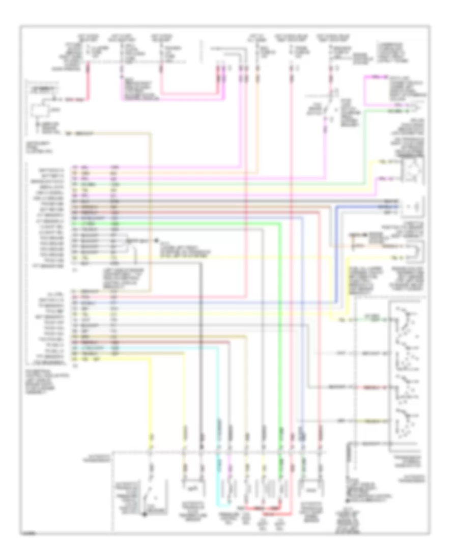
A/T Wiring Diagram for Buick Century Limited 2005
List of elements for A/T Wiring Diagram for Buick Century Limited 2005:
- (fuel inj jumper harness, midway between fuel injector 3 breakout & map sensor breakout)
- (left side of engine compartment, 7 cm from powertrain control module breakout)
- (on transaxle right axle case extension) vehicle speed sensor (vss)
- 1-2 shift sol
- 2-3 shift sol
- A/t sensor hi
- A/t sensor lo
- Automatic transaxle fluid pressure manual valve position switch
- Automatic transaxle fluid temperature sensor
- Automatic transaxle input shaft speed sensor
- Automatic transmission
- B12
- Battery in
- Brake switch in
- C2 c
- Cluster fuse 10a
- Data link connector (dlc) (under left side of dash, right of steering column)
- Ecm fuse 22 10a
- Ect return
- Ect sensor in
- Eng emis fuse 30 10a
- Engine controls system
- Engine coolant temperature (ect) sensor (top left side of engine, below throttle body)
- G113 (lower left front of engine, on transaxle stud, left of starter)
- Hot at all times
- Hot in off, run or start
- Hot in run or start
- Hot in run, bulb test or start
- I/p fuse block (behind right side of dash, in right door opening)
- Ign 0 clstr, pcm & bcm fuse 10a
- Ignition (0) in
- Ignition (1) in
- Instrument panel cluster (ipc)
- Logic
- Mil ctrl
- P r n
- Pc sol hi
- Pc sol lo
- Pcm ground
- Pcm-bcm u/h fuse 10a
- Pnk
- Powertrain control module (pcm) (left side of engine compt, in air cleaner assembly)
- Pressure control sol
- Red
- S115
- S121
- S270 (behind right side of dash, 4 cm from blower motor control module)
- Serial data
- Service engine soon ind
- Splice pack sp205 (behind data link connector)
- Stop lamp switch (on brake pedal support bracket)
- Tan
- Tcc pwm sol
- Tcc release
- Tcc release in
- Tcc/ brake switch
- Tft sensor gnd
- Tft sensor in
- Throttle position (tp) sensor (on throttle body assembly)
- Tp 5v ref
- Tp sensor in
- Tps return
- Tr sw in-a
- Tr sw in-b
- Tr sw in-c
- Tr sw in-p
- Trans fuse 26 10a
- Transmission internal mode switch
- Underhood fuse block (mounted to right front strut tower)
- Vf display
- Vss hi (signal)
- Vss lo (ground)
 English