AIR CONDITIONING
Automatic A/C Wiring Diagram for Chevrolet Corvette Z06 2002

List of elements for Automatic A/C Wiring Diagram for Chevrolet Corvette Z06 2002:
- +5v
- 5 volt ref
- A/c clu relay
- A/c compressor clutch
- A/c compressor clutch diode (in forward lamp harn, near a/c clutch connector)
- A/c fuse 24 10a
- A/c on
- A/c refrigerant pressure sensor (attached to the a/c high side line)
- Air inlet
- Air temperature actuator (left) (left side of hvac module)
- Air temperature actuator (right) (right side of hvac module)
- Air temperature sensor (inside) (in air outlet, right of steering column)
- All times
- Ambient temperature sensor (right front of engine compt)
- Battery
- Blo mot fuse 51 30a
- Blower motor control processor (behind right side of dash)
- Blwr mtr spd ctrl
- C10
- C11
- C12
- C13
- C14
- C15
- Class 2 serial
- Cool fan 1 fuse 49 30a
- Cool fan 2 fuse 46 30a
- Cool fan 3 fuse 14 10a
- Cooling fan (left)
- Cooling fan (right)
- Cooling fan 1 relay
- Cooling fan 2 relay
- Cooling fan 3 relay
- D10
- D11
- D12
- D13
- D14
- D15
- D16
- Data line
- Data link connector (dlc) (under dash, below steering column)
- Def mode sol ctrl
- Defrost
- E10
- Ect sensor
- Engine coolant temperature (ect) sensor (left side of engine, below generator)
- F11
- G102
- G102 (behind right headlamp)
- G202
- Gnd
- Heater
- Hot at
- Hot at all times
- Hot in run
- Hvac con fuse 27 10a
- Hvac control module
- Hvac fuse 18 10a
- Ign 3 volt
- In air temp sens
- Instrument panel fuse block (right front footwell, mounted to toe board)
- Low mode sol ctrl
- Mix-blend sol ctrl
- Mode closed
- Mode open
- Nca
- Or start
- Out air temp sens
- Pnk
- Powertrain control module (pcm) (behind right front fender, between wheelhouse dash panel)
- Press sig
- Recirc sol ctrl
- Red
- Relay ctrl
- S201 (dash harn, 35 cm from hvac module)
- S215 (dash harn, 6.5 cm from airbag module breakout)
- Sens gnd
- Solid state
- Splice pack sp100 (behind right headlamp)
- Splice pack sp202 (right kick panel)
- Star connector 1 (in dash harness)
- Sunload isig
- Sunload sensor (top of dash, right side of defroster grille)
- Tan
- Temp dr ctrl
- Temp dr ctrl-aux
- Temp dr pos sig
- Temp dr pos-aux
- Underhood fuse block (right rear of engine compt)
- Up mode sol ctrl
- Vacuum control assembly
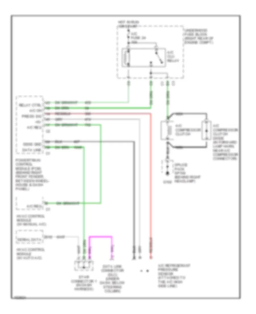
Compressor Wiring Diagram for Chevrolet Corvette Z06 2002
List of elements for Compressor Wiring Diagram for Chevrolet Corvette Z06 2002:
- +5v
- A/c clu relay
- A/c compressor clutch
- A/c compressor clutch diode (in forward lamp harn, near a/c compressor connector)
- A/c fuse 24 10a
- A/c on
- A/c refrigerant pressure sensor (attached to the a/c high side line)
- A/c req
- D12
- Data line
- Data link connector (dlc) (under dash, below steering column)
- G102
- Hot in run or start
- Hvac control module (w/ auto a/c)
- Hvac control module (w/ manual a/c)
- Nca
- Powertrain control module (pcm) (behind right front fender, between wheel- house & dash panel)
- Press sig
- Relay ctrl
- Sens gnd
- Serial data
- Splice pack sp100 (behind right headlamp)
- Star connector 1 (in dash harness)
- Underhood fuse block (right rear of engine compt)
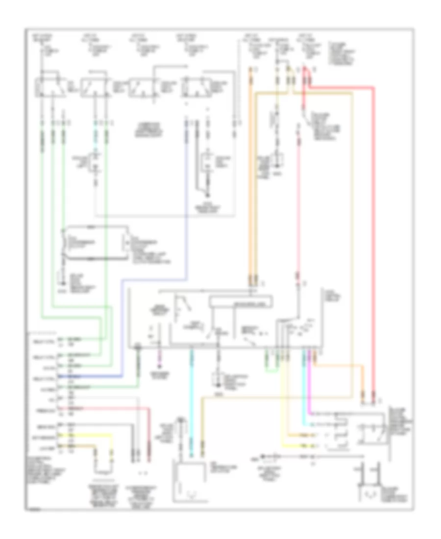
Manual A/C Wiring Diagram for Chevrolet Corvette Z06 2002
List of elements for Manual A/C Wiring Diagram for Chevrolet Corvette Z06 2002:
- +5v
- A/c clu relay
- A/c compressor clutch
- A/c compressor clutch diode (in forward lamp harn, near a/c clutch connector)
- A/c fuse 24 10a
- A/c on
- A/c refrigerant pressure sensor (attached to the a/c high side line)
- A/c req
- Air recirc
- Air source logic
- Air temperature actuator
- All times
- Blo mot maxi fuse 51 30a
- Blower motor (under right side of dash
- Blower motor control processor (behind right side of dash)
- Blower motor relay (on multi-use relay & fuse bracket, above bcm)
- Coolfan 1 fuse 49 30a
- Coolfan 2 fuse 46 30a
- Coolfan 3 fuse 14 10a
- Cooling fan (left)
- Cooling fan (right)
- Cooling fan 1 relay
- Cooling fan 2 relay
- Cooling fan 3 relay
- D10
- Defogger system
- Defrost/ defog
- E10
- Ect sensor
- Engine coolant temperature (ect) sensor (left side of engine, below generator)
- F11
- G tan
- G102
- G102 (behind right headlamp)
- G201
- G202
- Hot at
- Hot in run
- Hvac fuse 18 10a
- Hvac con mini fuse 27 10a
- Hvac control module
- I/p fuse block (right front footwell, mounted to toe board)
- Low ref
- Nca
- Off
- Or start
- Powertrain control module (pcm) (behind right front fender, between wheelhouse & dash panel)
- Press sig
- Rear defogger circuit
- Red
- Relay ctrl
- Sens gnd
- Splice pack sp100 (behind right headlamp)
- Splice pack sp201 (left kick panel)
- Splice pack sp202 (right kick panel)
- Tan
- Temp control
- Underhood fuse block (right rear of engine compt)