SUPPLEMENTAL RESTRAINTS
Supplemental Restraint Wiring Diagram for Chevrolet Corvette Z06 2002
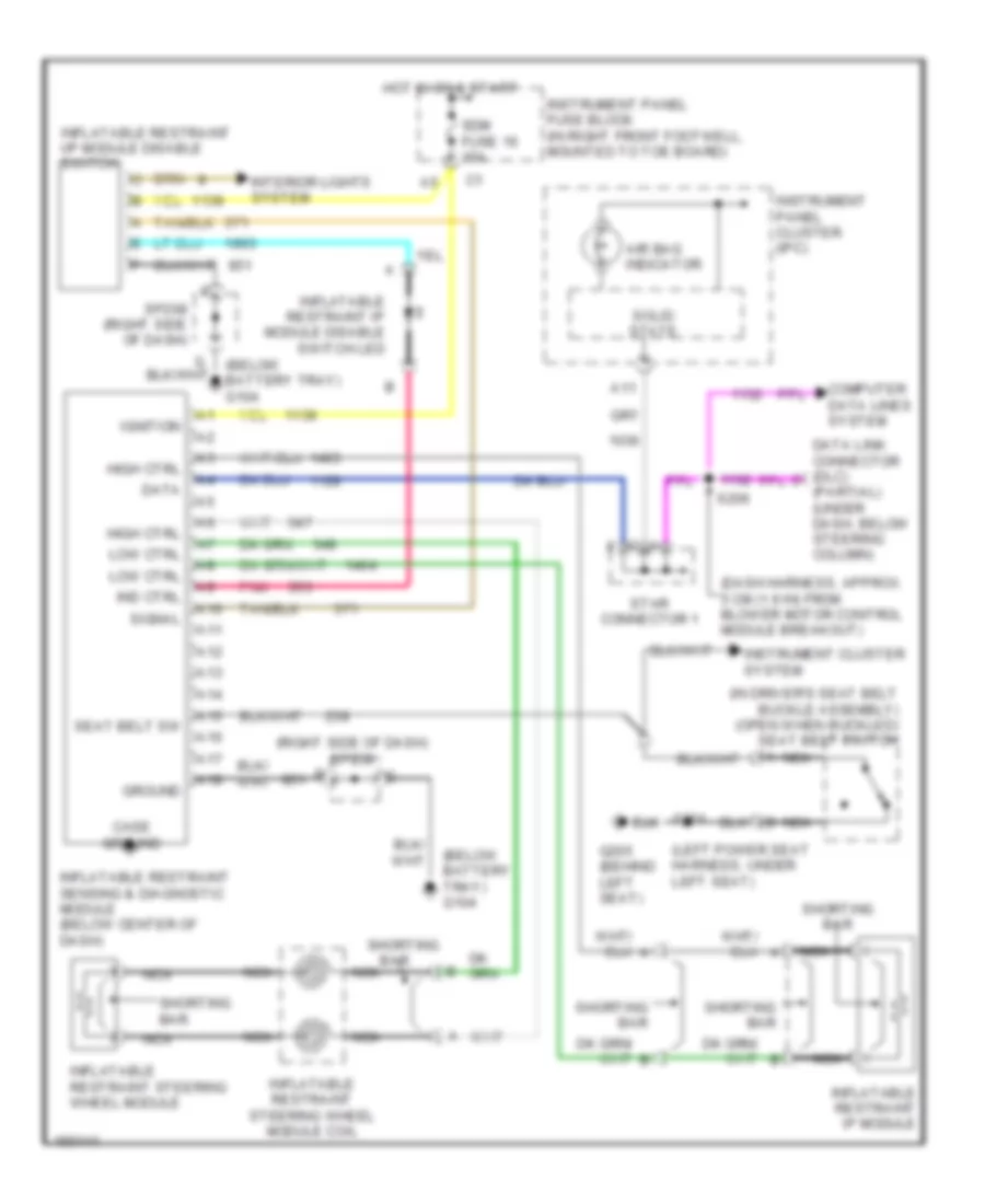
List of elements for Supplemental Restraint Wiring Diagram for Chevrolet Corvette Z06 2002:
- (below
- (below battery tray) g104
- (dash harness, approx. 5 cm (1.9 in) from blower motor control module breakout)
- (in driver's seat belt buckle assembly) (open when buckled) seat belt switch
- (left power seat harness, under left seat)
- (partial) (under dash, below steering column)
- (right side of dash) sp208
- A10
- A11
- A12
- A13
- A14
- A15
- A16
- A17
- A18
- Air bag indicator
- B nca
- Bar
- Case ground
- Computer data lines system
- Data
- G205 (behind left seat)
- Ground
- High ctrl
- Hot in on & start
- Ignition
- Ind ctrl
- Inflatable restraint i/p module disable switch
- Inflatable restraint ip module
- Inflatable restraint ip module disable switch led
- Inflatable restraint sensing & diagnostic module (below center of dash)
- Inflatable restraint steering wheel module
- Inflatable restraint steering wheel module coil
- Instrument cluster system
- Instrument panel cluster (ipc)
- Instrument panel fuse block (in right front footwell, mounted to toe board)
- Interior lights system
- Low ctrl
- Nca
- Pnk
- S206
- S301
- Sdm fuse 16 15a
- Seat belt sw
- Shorting
- Shorting bar
- Signal
- Solid state
- Sp208 (right side of dash)
- Star connector 1
 English