AIR CONDITIONING
A/C Wiring Diagram, Auto A/C (1 of 2) for Chevrolet Corvette ZR-1 1995

List of elements for A/C Wiring Diagram, Auto A/C (1 of 2) for Chevrolet Corvette ZR-1 1995:
- (top center of i/p)
- +5 v ref
- +8 v ref
- +8 volt ref
- A/c blower fuse 4 30a
- A/c clutch fuse 18 10a
- A/c mdl fuse 1 5a
- A/c pressure cycling switch (right rear of engine compartment in a/c low pressure pipe)
- A/c prog fuse 43 5a
- A/c request out
- Air mix valve motor
- Battery
- Blower feedback
- Blower motor
- Blower motor control module (right rear of engine compartment)
- Blower speed ctrl
- C 1995 vftc
- C10
- C11
- C12
- C13
- C14
- C15
- C16
- Computer data lines system
- Control button led
- D10
- D11
- D12
- D13
- D14
- D15
- D16
- Data line
- G105 (right rear of engine compartment)
- G200 (behind left i/p on kick panel)
- Ground
- Hot at all times
- Hot in run
- Hvac control head
- Hvac programmer (below left side of i/p, right of steering column)
- I/p fuse block
- Ignition fused feed
- Ignition input
- Illumination
- Inside air temperature sensor (behind right side of i/p)
- Inside temp sensor
- Interior lights system
- Lcd display feed
- Mix valve feedbk
- Nca
- Outside temp sensor
- Outside temperature sensor (in right radiator shroud)
- Rear defog on
- Rear defog req
- Rear defogger system
- Red
- Sensor ground
- Serial data
- Solar sensor
- Sun load sensor
- Tan
- Temperature door motor (behind right side of i/p, on bottom heater case)
- Underhood fuse block 1
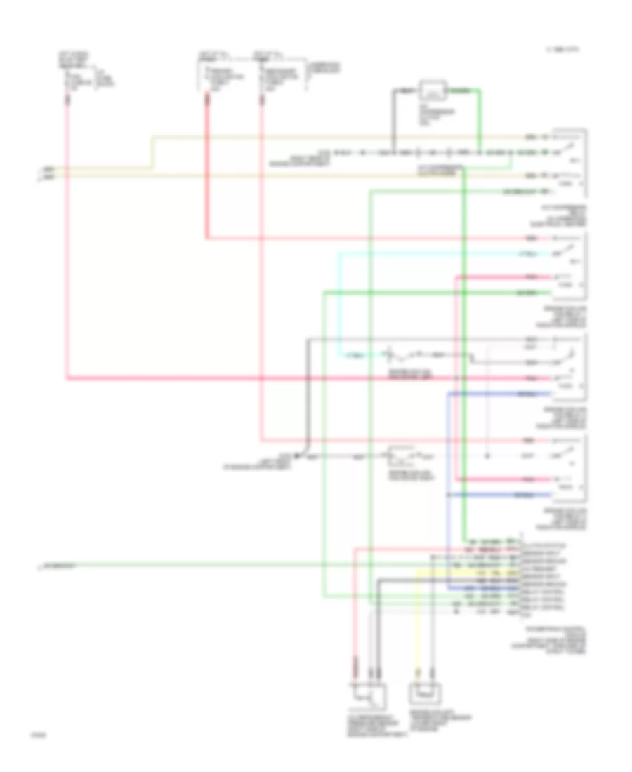
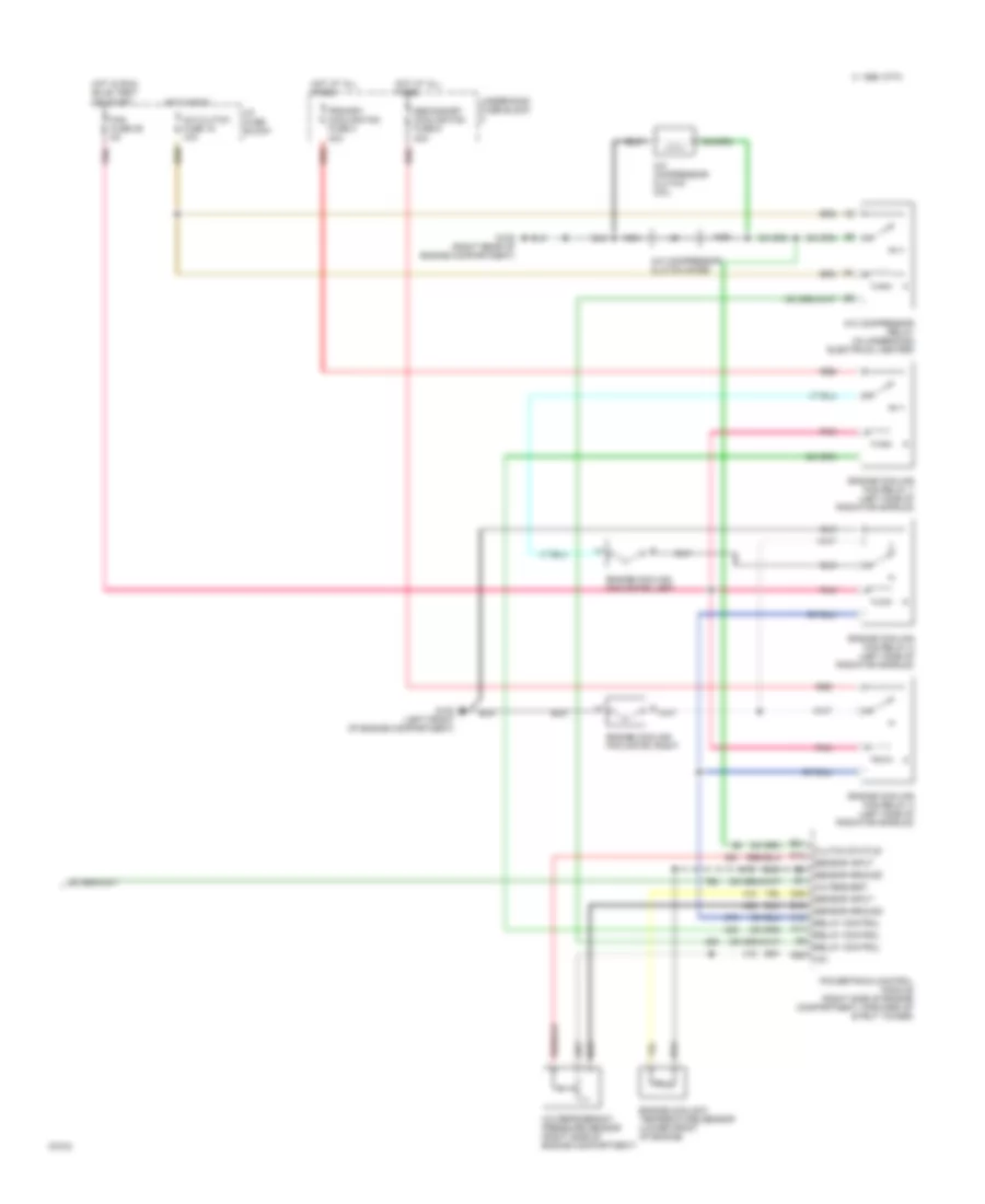
A/C Wiring Diagram, Auto A/C (2 of 2) for Chevrolet Corvette ZR-1 1995
List of elements for A/C Wiring Diagram, Auto A/C (2 of 2) for Chevrolet Corvette ZR-1 1995:
- +5v
- A/c compressor clutch coil
- A/c compressor clutch diode
- A/c compressor relay (in underhood electrical center)
- A/c refrigerant pressure sensor (right side of engine compartment)
- A/c request
- A10
- A11
- B16
- B21
- B29
- C 1995 vftc
- C25
- Clutch status
- D12
- Engine coolant temperature sensor (lower front of engine)
- Engine cooling fan motor, left
- Engine cooling fan motor, right
- Engine cooling fan relay 1 (left side of radiator shroud)
- Engine cooling fan relay 2 (left side of radiator shroud)
- Engine cooling fan relay 3 (left side of radiator shroud)
- Fan fuse 29 5a
- G100 (left front of engine compartment)
- G105 (right rear of engine compartment)
- Hot at all times
- Hot in run, bulb test,
- I/p fuse block
- Nca
- Or start
- Pnk
- Powertrain control module (right side of engine compartment, forward of strut tower)
- Primary cooling fan fuse 2 30a
- Red
- Relay control
- Secondary cooling fan fuse 5 40a
- Sensor ground
- Sensor input
- Underhood fuse block
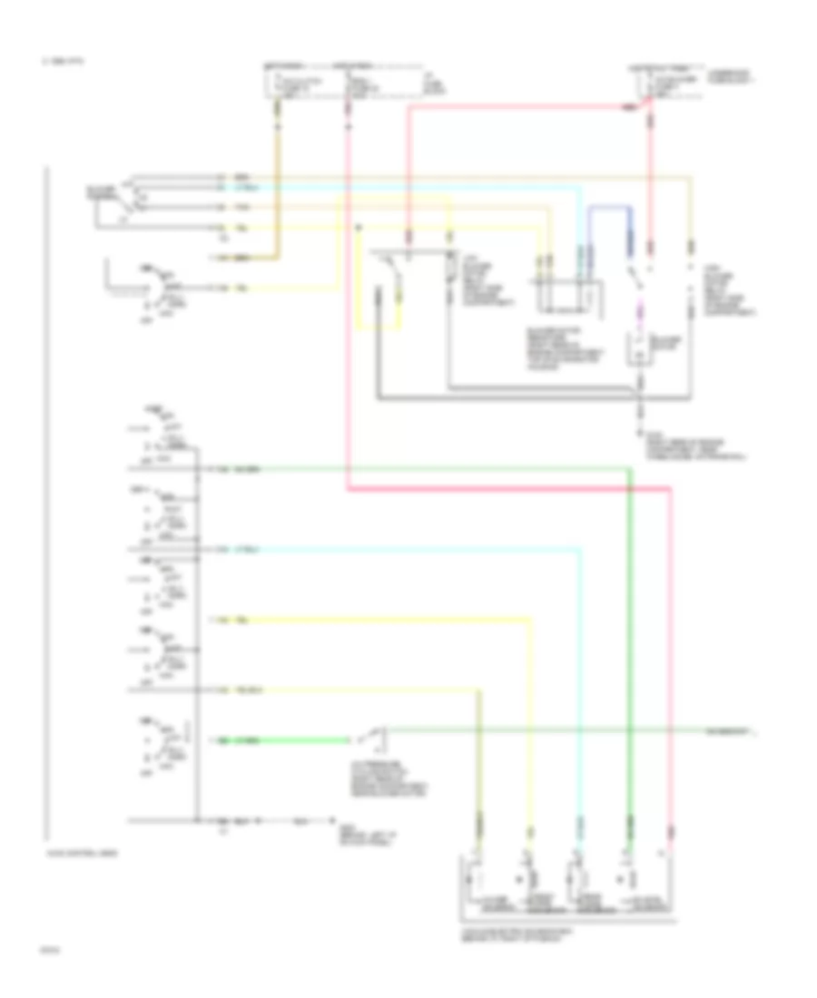
A/C Wiring Diagram, Manual A/C (1 of 2) for Chevrolet Corvette ZR-1 1995
List of elements for A/C Wiring Diagram, Manual A/C (1 of 2) for Chevrolet Corvette ZR-1 1995:
- A/c blower fuse 4 30a
- A/c clutch fuse 18 10a
- A/c pressure cycling switch (right rear of engine compartment, near blower motor)
- A/c-def solenoid
- B-lv norm
- Bi-level solenoid
- Blower motor
- Blower motor resistors (right rear of engine compartment, top of evaporator housing)
- Blower switch
- C 1995 vftc
- Def
- Eng 1 fuse 30 10a
- Front mode solenoid
- G105 (right rear of engine compartment, near wheelhouse, on frame rail)
- G200 (behind left i/p on kick panel)
- High blower motor relay (right side of engine compartment)
- Hot at all times
- Hot in run
- Htr
- Hvac control head
- I/p fuse block
- Low blower motor relay (right side of engine compartment)
- Max
- Off
- Pnk
- Rear mode solenoid
- Red
- Tan
- Underhood fuse block 1
- Vacuum/electric solenoid box (behind i/p, right of plenum)
- Vnt
A/C Wiring Diagram, Manual A/C (2 of 2) for Chevrolet Corvette ZR-1 1995
List of elements for A/C Wiring Diagram, Manual A/C (2 of 2) for Chevrolet Corvette ZR-1 1995:
- +5v
- A/c clutch fuse 18 10a
- A/c compressor clutch coil
- A/c compressor clutch diode
- A/c compressor relay (in underhood electrical center)
- A/c refrigerant pressure sensor (right side of engine compartment)
- A/c request
- A10
- A11
- B16
- B21
- B29
- C 1995 vftc
- C25
- Clutch status
- D12
- Engine coolant temperature sensor (lower front of engine)
- Engine cooling fan motor, left
- Engine cooling fan motor, right
- Engine cooling fan relay 1 (left side of radiator shroud)
- Engine cooling fan relay 2 (left side of radiator shroud)
- Engine cooling fan relay 3 (left side of radiator shroud)
- Fan fuse 29 5a
- G100 (left front of engine compartment)
- G105 (right rear of engine compartment)
- Hot at all times
- Hot in run
- Hot in run, bulb test,
- I/p fuse block
- Nca
- Or start
- Pnk
- Powertrain control module (right side of engine compartment, forward of strut tower)
- Primary cooling fan fuse 2 30a
- Red
- Relay control
- Secondary cooling fan fuse 5 40a
- Sensor ground
- Sensor input
- Underhood fuse block