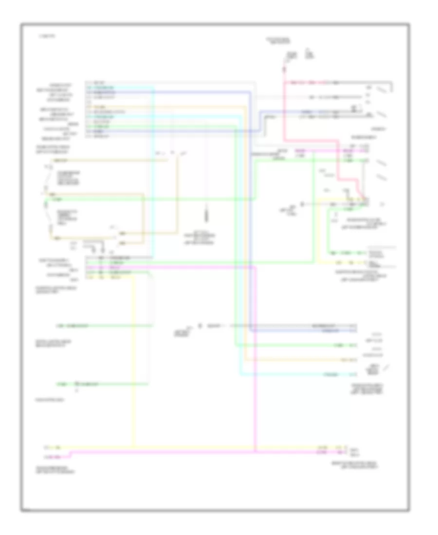
CRUISE CONTROL
Cruise Control Wiring Diagram for Chevrolet Corvette ZR-1 1995
List of elements for Cruise Control Wiring Diagram for Chevrolet Corvette ZR-1 1995:
- (left cargo compartment)
- (above battery)
- (asr ind)
- (behind center of i/p)
- (left kick
- (left of i/p fuse block)
- (left of steering column)
- (left rear
- (left rear of engine
- (left rear of engine)
- (left rear of transmission)
- (right rear of engine)
- (top of brake
- (top of clutch
- 1995 vftc c
- 4000 pulses/mile
- A/t
- A11
- A17
- A31
- A32
- Active sig
- Asr active signal
- Assembly
- B22
- Block
- Brake switch
- C11
- C15
- Central control module
- Clutch sw
- Compt, above battery)
- Control
- Control module
- Cruise
- Cruise control cut off
- Cruise control module
- Cruise control servo
- Cruise engage sw
- Cruise on input
- Cruise release
- Cruise sw
- Cut off relay
- Disengage input
- Driver
- Elec trans sched in
- Elec trans sched out
- Electronic brake & traction
- Fuse
- Fuse 32
- G114
- G114 (vin p)
- G117 (vin j)
- G200
- Ground
- Hot in run, bulb
- I/p
- Information center
- M/t
- Nca
- Of engine)
- Off
- Panel)
- Pedal bracket)
- Pedal)
- Pnk
- Position
- Powertrain control module
- R/a
- Radio control head
- Relay
- Resume/accel input
- Selective ride control module
- Sensor
- Servo
- Servo position in/hi
- Servo position in/lo
- Set
- Set input
- Tan
- Tan 398
- Test or start
- Traction
- Vacuum valve
- Vacuum valve ctrl
- Vehicle speed sensor
- Vent valve
- Vent valve ctrl
- Vin j
- Vin p
- Vss hi
- Vss lo
 English