AIR CONDITIONING
Automatic A/C Wiring Diagram (1 of 3) for Ford C-Max Hybrid SE 2014

List of elements for Automatic A/C Wiring Diagram (1 of 3) for Ford C-Max Hybrid SE 2014:
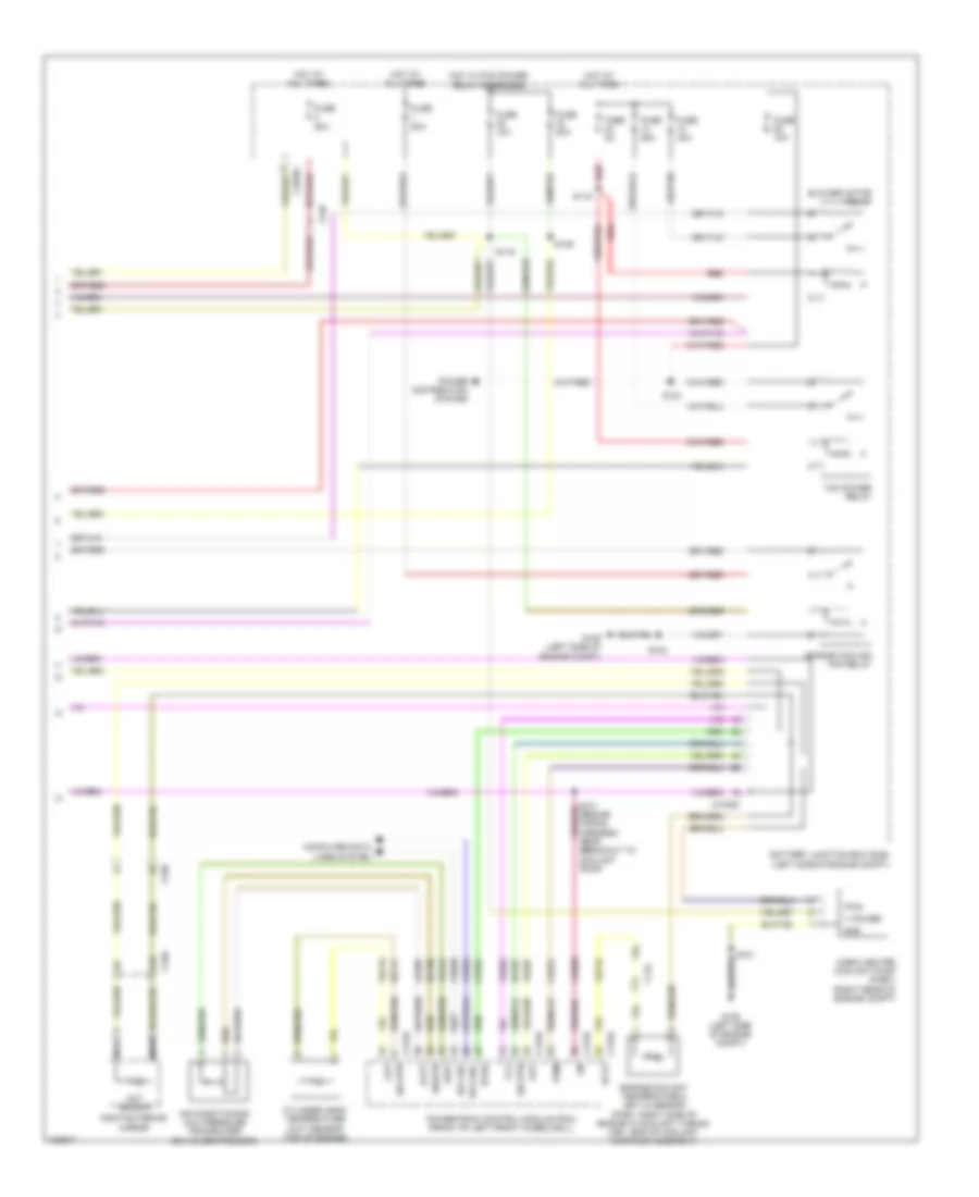
Automatic A/C Wiring Diagram (2 of 3) for Ford C-Max Hybrid SE 2014
List of elements for Automatic A/C Wiring Diagram (2 of 3) for Ford C-Max Hybrid SE 2014:
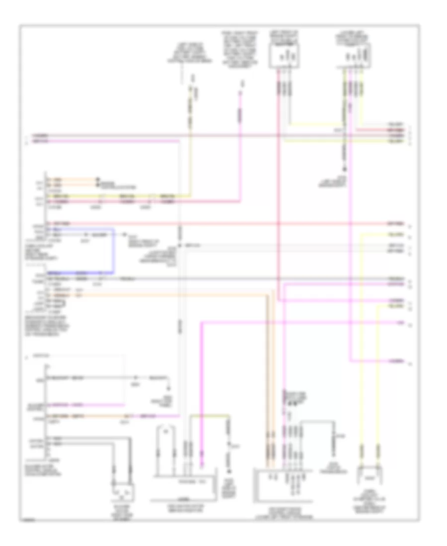
Automatic A/C Wiring Diagram (3 of 3) for Ford C-Max Hybrid SE 2014
List of elements for Automatic A/C Wiring Diagram (3 of 3) for Ford C-Max Hybrid SE 2014: