POWER DISTRIBUTION
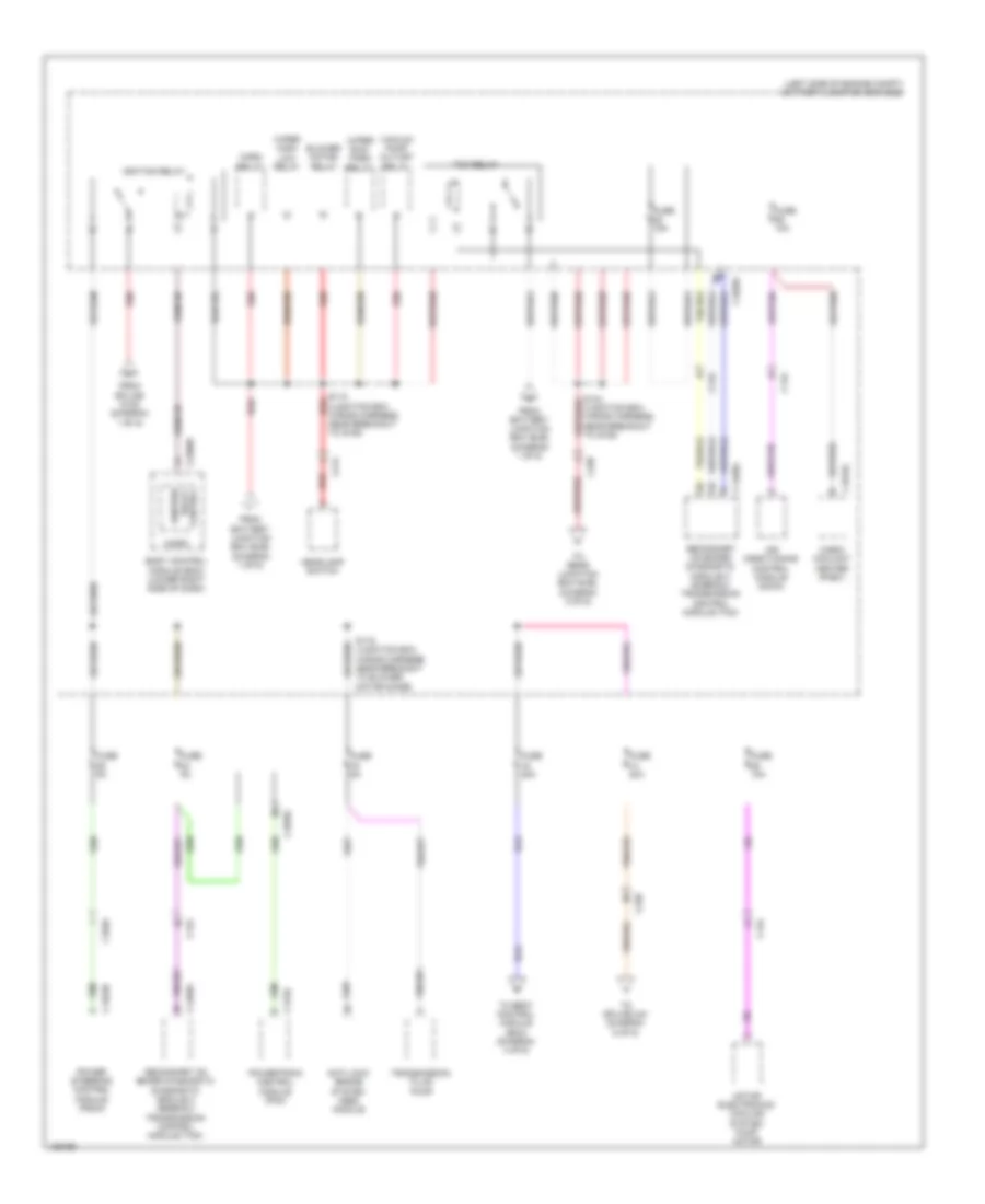
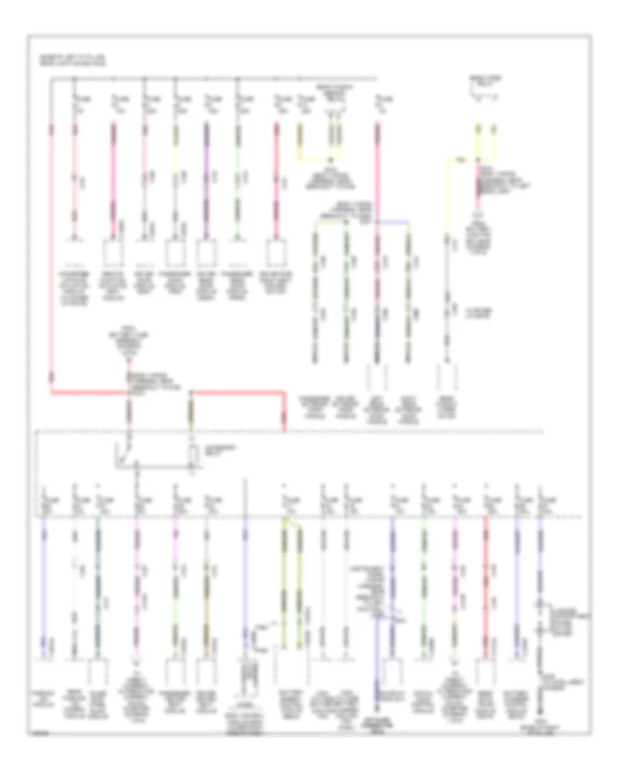
Power Distribution Wiring Diagram (1 of 6) for Ford C-Max Hybrid SE 2014

List of elements for Power Distribution Wiring Diagram (1 of 6) for Ford C-Max Hybrid SE 2014:
- (engine wiring harness, near breakout to map sensor) s130
- 150a
- Anti-lock brake system (abs) module
- Battery
- Battery fuse assembly
- Battery junction box (bjb) (left side of engine compt)
- Battery monitoring sensor
- Blower motor relay
- Brake pedal position (bpp)
- C1035c
- C1045
- C140
- C1458a
- C1463a
- C175b
- C4453d
- Charge port light ring
- Coolant water pump 1
- Dc/dc converter module
- Direct current/ alternating current (dc/ac) inverter
- Engine cooling fan relay
- From rear junction box (rjb) (diagram 6 of 6)
- Fuel injector 1
- Fuel injector 2
- Fuel injector 3
- Fuel injector 4
- Fuse 1 80a
- Fuse 10a
- Fuse 15a
- Fuse 2 175a
- Fuse 20a
- Fuse 25a
- Fuse 30a
- Fuse 40a
- Fuse 50a
- Fuse 5a
- G202 (right kick panel)
- G401 (right side of high voltage battery compt)
- High current battery junction box (bjb) (right side of high voltage battery compt)
- Horn relay
- Nca
- Pcm power relay
- Power steering control module (pscm)
- Powertrain control module (pcm)
- Red
- S105 (junction box wiring harness, near breakout to g105)
- S347
- Secondary on board diagnostic module c (sobdmc)/ transmission control module (tcm)
- Switch
- To battery junction box (bjb) (diagram 2 of 6)
- To body control module (bcm) (diagram 4 of 6)
- To body control module (bcm) (diagram 5 of 6)
- To fuse 33 (diagram 3 of 6)
- To splice 115 (diagram 2 of 6)
- To splice s342 (diagram 6 of 6)
- Trans- mission fluid pump
- Vacuum pump cut-off relay
- Wiper run/park relay
Power Distribution Wiring Diagram (2 of 6) for Ford C-Max Hybrid SE 2014
List of elements for Power Distribution Wiring Diagram (2 of 6) for Ford C-Max Hybrid SE 2014:
- (junction box wiring harness, near breakout to g105)
- (left side of engine compt) battery junction box (bjb)
- Air conditioning control module (accm)
- Anti-lock brake system (abs) module
- Blower motor relay
- Body control module (bcm) (lower right side of dash)
- C1035c
- C1046
- C134
- C1458a
- C1463b
- C175b
- C1815c
- C214
- C2280d
- C238
- Cabin coolant heater (phev)
- From battery junction box (bjb) (diagram 1 of 6)
- From splice s105 (diagram 1 of 6)
- Fuse 10a
- Fuse 15a
- Fuse 20a
- Fuse 5a
- Headlamp switch
- Horn relay
- Ignition relay
- Ignition relay control
- Micro
- Motor electronics cooling system pump motor
- Power steering control module (pscm)
- Powertrain control module (pcm)
- Red
- S115 (junction box wiring harness, near breakout to g105)
- S116 (junction box wiring harness, near breakout to blower motor diode)
- Secondary on board diagnostic diagnostic module c (sobdmc)/ transmission control module (tcm)
- Secondary on board diagnostic module c (sobdmc)/ transmission control module (tcm)
- Tcm relay
- To body control module (bcm) (diagram 4 of 6)
- To rear junction box (rjb) (diagram 5 of 6)
- To splice 344 (diagram 6 of 6)
- Transmission fluid pump
- Vacuum pump cut-off relay
- Wiper high/ low relay
- Wiper run/ park relay
Power Distribution Wiring Diagram (3 of 6) for Ford C-Max Hybrid SE 2014
List of elements for Power Distribution Wiring Diagram (3 of 6) for Ford C-Max Hybrid SE 2014:
- (body wiring harness, near breakout to c212) s322
- (engine wiring harness, near breakout to cmp sensor) s132
- (instrument panel wiring harness, near breakout to bcm) s238
- (left side of engine compt) battery junction box (bjb)
- (lower right side of dash) body control module (bcm)
- (not used)
- (roof wiring harness, near breakout to right vanity mirror) s901
- Active grille shutter
- C1035c
- C211
- C2280e
- C2280f
- C238
- C339
- C4198
- C4403
- Cabin heater coolant diverter valve
- Cabin heater coolant pump
- Coil on plug (cop) 1
- Coil on plug (cop) 2
- Coil on plug (cop) 3
- Coil on plug (cop) 4
- Coolant water pump 1
- Driver door window control switch
- Driver side interior lamp (w/ roof opening panel)
- Electric exhaust gas recirculation (eegr) valve
- Engine cooling fan relay
- Evaporative emission canister purge valve
- From fuse 34 m (diagram 1 of 6)
- From fuse 62 l (diagram 4 of 6)
- Front interior lamp (w/o roof opening panel)
- Fuse 10a
- Fuse 15a
- Fuse 20a
- Fuse 5a
- Glove compart- ment lamp
- Heated oxygen sensor (ho2s) 12
- Ignition coil 1
- Left footwell lamp (w/o ambient lighting)
- Left vanity mirror lamp
- Luggage compart- ment lamp
- Nca
- Overhead console switch assembly
- Passenger side interior lamp (w/ roof opening panel)
- Passive anti-theft system (pats) transceiver
- Rear interior lamp
- Right footwell lamp (w/o ambient lighting)
- Right vanity mirror lamp
- S106 (junction box wiring harness, near breakout to c214)
- S119 (junction box wiring harness, near breakout to g104)
- S133 (engine wiring harness, near breakout to knock sensor 1)
- To rear junction box (rjb) (diagram 5 of 6)
- Universal heated oxygen sensor (ho2s) 11
- Variable camshaft timing 11 (vct11)
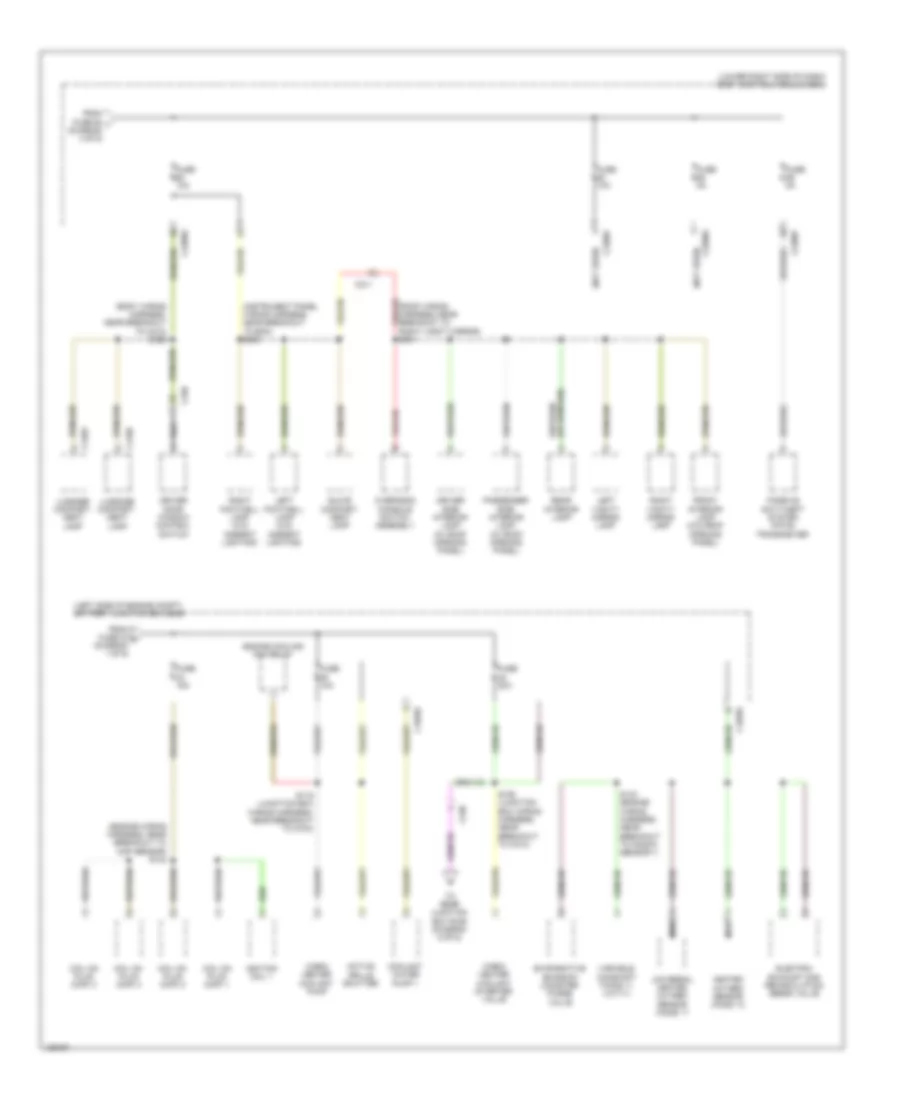
Power Distribution Wiring Diagram (4 of 6) for Ford C-Max Hybrid SE 2014
List of elements for Power Distribution Wiring Diagram (4 of 6) for Ford C-Max Hybrid SE 2014:
- (body wiring harness, near breakout to g301) s309
- (instrument panel
- (instrument panel wiring harness, near breakout to blend door actuators) s214
- (instrument panel wiring harness, near breakout to glove box lamp) s243
- (lower right side of dash) body control module (bcm)
- (not used)
- Accessory protocol interface module (apim)
- Audio control module (acm)
- C212a
- C212b
- C2280d
- C2280e
- C2280f
- C2280g
- C2280h
- C228b
- C237
- C240a
- C310a
- C311
- C312
- C319
- C3191a
- C3192a
- C380
- Cigar lighter
- Driver heated seat module
- Driver heated seat switch
- From battery junction box (bjb) (diagram 1 of 6)
- From battery junction box (bjb) (diagram 2 of 6)
- Front control/ display interface module (fcdim)
- Front controls interface module (fcim)
- Fuse 10a
- Fuse 15a
- Fuse 20a
- Fuse 5a
- Fuse 7.5a
- G202 (right kick panel)
- Gateway module a (gwm)
- Glass roof panel blind module
- Global positioning system module (gpsm)
- Heating ventilation & air conditioning (hvac) control module
- Instrument panel cluster (ipc)
- Interior light relay
- Liftgate/ decklid release relay
- Micro
- Occupant classification system module (ocsm)
- Passenger air bag deactivation (pad) indicator
- Passenger heated seat module
- Passenger heated seat switch
- Radio frequency (rf) receiver
- Rain sensor
- Red
- Restraints control module (rcm)
- S340 (body wiring harness, near breakout to c311)
- S347
- S356
- Spare relay
- Steering angle sensor module (sasm)
- Telematic control unit module (tcu)
- To c210) s237
- To fuse 60 (diagram 3 of 6)
- Trans- mission control switch (tcs)
- Vpwr
- W/ heated seats
- Wiring harness, near breakout to c210) s236
- Wiring harness, near breakout to g202) s242
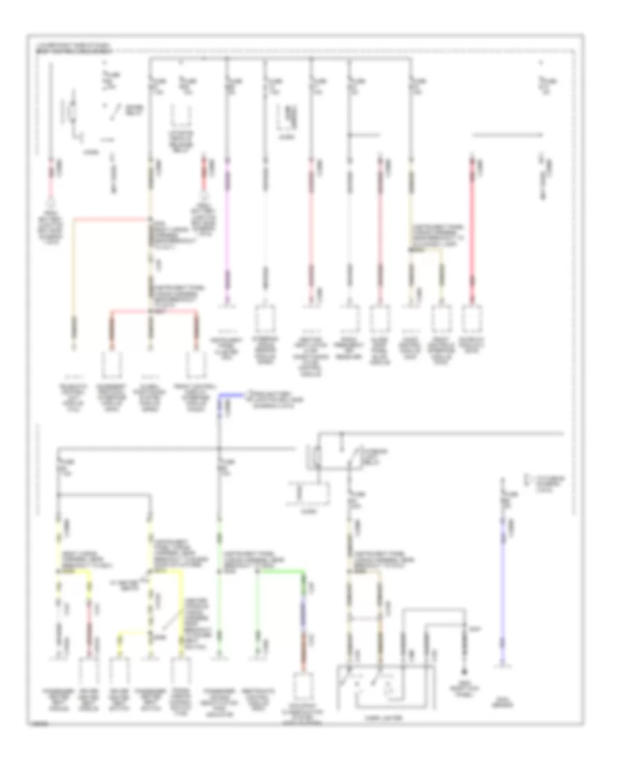
Power Distribution Wiring Diagram (5 of 6) for Ford C-Max Hybrid SE 2014
List of elements for Power Distribution Wiring Diagram (5 of 6) for Ford C-Max Hybrid SE 2014:
- (base of left "d" pillar) rear junction box (rjb)
- (instrument panel wiring harness, near breakout to blend door actuators) s231
- (lower right side of dash) body control module (bcm)
- Acc
- Acc run
- Acc/ run
- Battery charger control module (bccm) (phev)
- Battery energy control module (becm)
- Battery junction box (bjb) (left side of engine compt) c1035c
- Body control module (bcm) (lower right side of dash)
- C175b
- C214
- C2280c
- C2280f
- C2280g
- C237
- C315
- C4237a
- C4392d
- C4455a
- C4816a
- Evaporative emission (evap) leak detection control module
- Fhev
- Fog lamp relay
- From battery junction box (bjb) (diagram 1 of 6)
- From splice 106 c (diagram 3 of 6)
- From splice 124 h (diagram 2 of 6)
- Front washer relay
- Fuel door release relay
- Fuel pump relay
- Fuel tank isolation valve (phev)
- Fuse 10a
- Fuse 15a
- Fuse 20a
- Fuse 5a
- High beam relay
- Ignition switch
- Illum
- Key in ign sw
- Key in ignition switch
- Lock
- Micro
- Nca
- Off
- Phev
- Powertrain control module (pcm)
- Rear washer relay
- Red
- Remote function actuator (rfa) module
- Reversing lamp relay
- Run
- S339 (body wiring harness, near breakout to rjb)
- S346 (rear axle wiring harness, near breakout to fuel tank unit)
- Start
- Start/ run
- Start/ stop sw 1
- Start/ stop sw 2
- Transmission control switch (tcs)
- Vapor management valve (fhev)
- W/ intelligent access
- W/o intelligent access
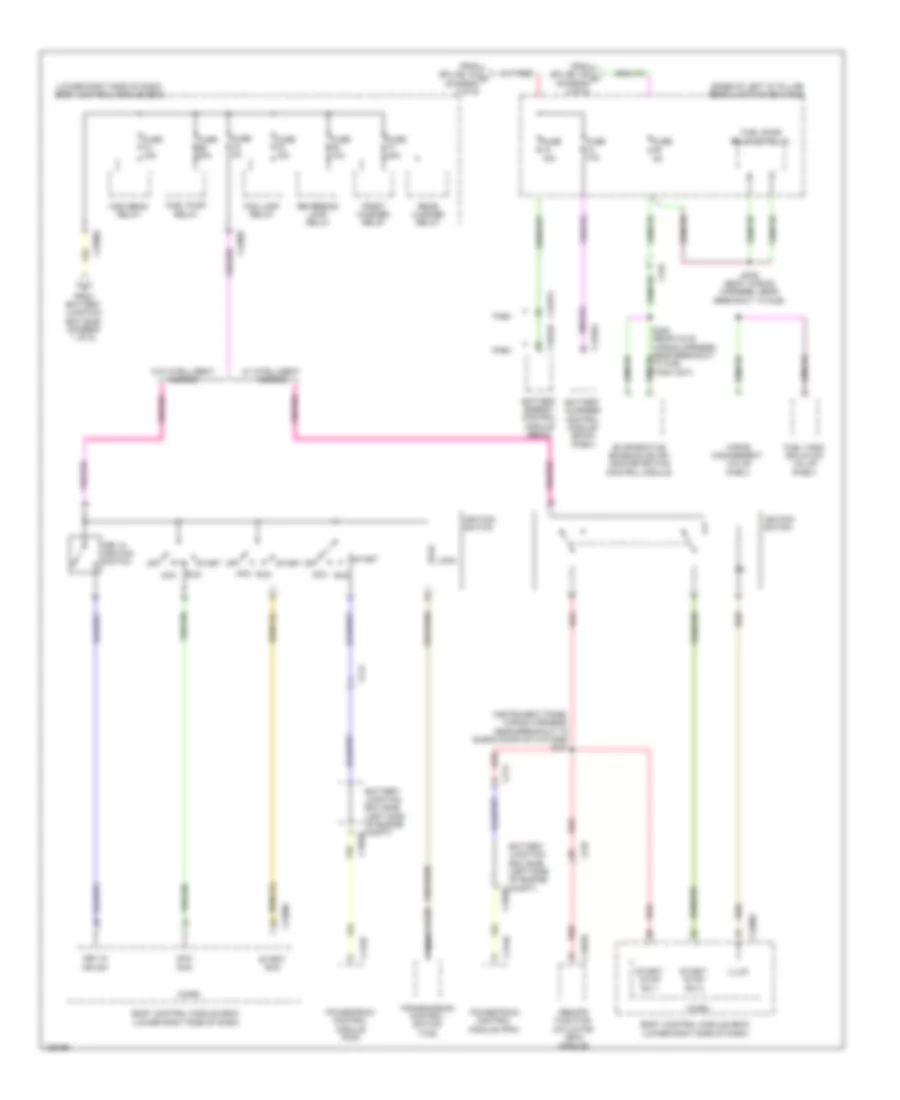
Power Distribution Wiring Diagram (6 of 6) for Ford C-Max Hybrid SE 2014
List of elements for Power Distribution Wiring Diagram (6 of 6) for Ford C-Max Hybrid SE 2014:
- (base of left "d" pillar) rear junction box (rjb)
- (body wiring harness, near breakout to g306) s321
- (body wiring harness, near breakout to rjb) s342
- (instrument panel wiring harness, near breakout to left footwell lamp)
- A14
- A17
- Accessory relay
- B17
- Battery charger control module (bccm)
- Battery energy control module (becm)
- Body control module (bcm) (lower right side of dash)
- Breakout to left rear lamp)
- C211
- C212a
- C212b
- C2280b
- C237
- C2488b
- C311
- C312
- C313
- C314
- C3191a
- C3192a
- C339
- C340
- C4014a
- C410
- C411
- C4174a
- C4237a
- C431
- C432
- C4392c
- C4455a
- C4816a
- C494
- C501a
- C510
- C610
- C652a
- C700
- C800
- Control relay accessory
- Datalink datalink connector connector (dlc) (dlc)
- Digital audio control module
- Driver door module (ddm)
- Driver exterior door handle
- Driver heated seat module
- Driver rear door module (drdm)
- Driver side front seat control switch
- Fhev
- From battery fuse assembly (diagram 1 of 6)
- From battery junction box (bjb) (diagram 2 of 6)
- Fuse 10a
- Fuse 15a
- Fuse 20a
- Fuse 25a
- Fuse 30a
- Fuse 40a
- Fuse 5a
- G304 (base of right "d" pillar)
- Gateway module a
- Glass roof panel blind module
- Handsfree liftgate actuation module (w/ power liftgate)
- High voltage battery charger cooling fan (phev)
- High voltage battery cooling fan
- Left rear exterior door handle
- Luggage compartment power outlet socket
- Micro
- Nca
- Parking aid module
- Passenger door module (pdm)
- Passenger exterior door handle
- Passenger heated seat module
- Passenger rear door module (prdm)
- Phev
- Rear gate trunk module (rgtm)
- Rear parking aid camera module
- Rear window defrost relay
- Rear window wiper motor
- Rear wiper relay
- Red
- Remote function actuator (rfa) module
- Right rear exterior door handle
- S221
- S325 (w/ intelligent access)
- S343 (body wiring harness, near breakout to rjb)
- To direct current/ alternating current (dc/ac) inverter (diagram 1 of 6)
- W/ power liftgate