AIR CONDITIONING
5.8L
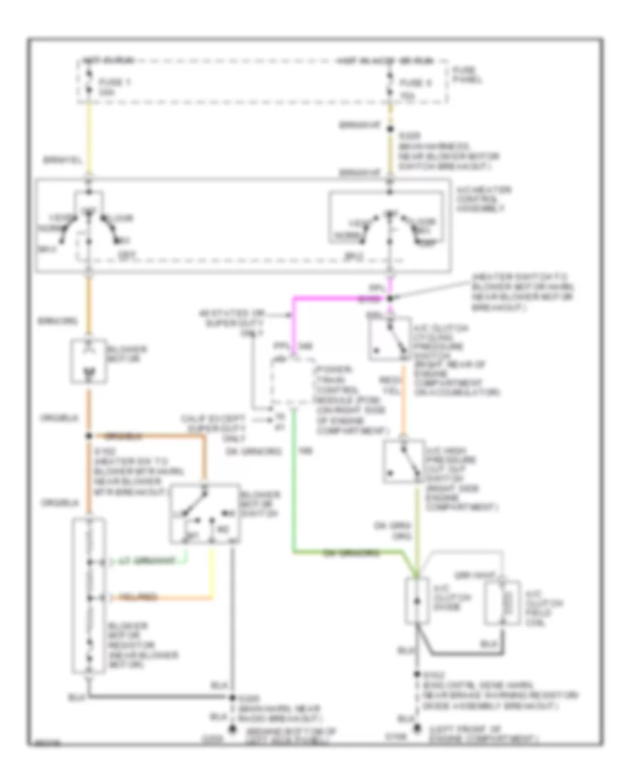
5.8L, A/C Wiring Diagram for Ford Cab & Chassis F350 1997

List of elements for 5.8L, A/C Wiring Diagram for Ford Cab & Chassis F350 1997:
- (behind bottom of left kick panel)
- (heater switch to blower motor harn, near blower motor breakout)
- (left front of engine compartment)
- 15a
- 49 states or super duty only
- A/c clutch cycling pressure switch (right rear of engine compartment on accumulator)
- A/c clutch diode
- A/c clutch field coil
- A/c high pressure cut out switch (right side engine compartment)
- A/c-heater control assembly
- Blower motor
- Blower motor resistor (near blower motor)
- Blower motor switch
- Calif except super duty only
- Def
- Floor
- Fuse 1 30a
- Fuse 6
- Fuse panel
- G108
- G200
- Hot in accy or run
- Hot in run
- Max
- Mix
- Norm
- Off
- Power- train control module (pcm) (on right side of engine compartment)
- S102 (eng cntrl sens harn, near brake warning resistor/ diode assembly breakout)
- S152 (heater sw to blower mtr harn, near blower mtr breakout)
- S153
- S205 (main harn, near radio breakout)
- S229 (main harness, near blower motor switch breakout)
- Vent
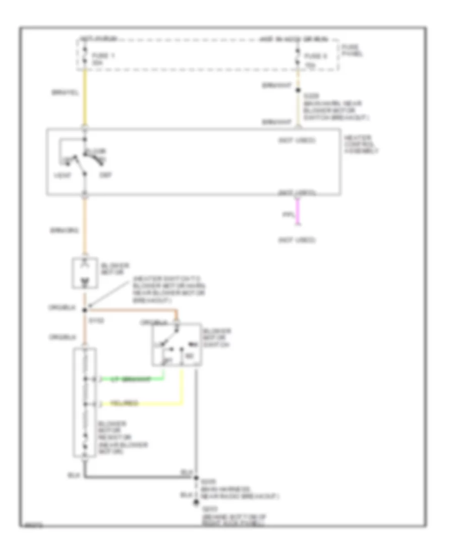
Heater Wiring Diagram for Ford Cab & Chassis F350 1997
List of elements for Heater Wiring Diagram for Ford Cab & Chassis F350 1997:
- (heater switch to blower motor harn, near blower motor breakout)
- (not used)
- 15a
- Blower motor
- Blower motor resistor (near blower motor)
- Blower motor switch
- Def
- Floor
- Fuse 1 30a
- Fuse 6
- Fuse panel
- G203 (behind bottom of right kick panel)
- Heater control assembly
- Hot in accy or run
- Hot in run
- Mix
- Off
- S152
- S205 (main harness, near radio breakout)
- S229 (main harn, near blower motor switch breakout)
- Vent
7.3L
7.3L DI Turbo Diesel, A/C Wiring Diagram for Ford Cab & Chassis F350 1997
List of elements for 7.3L DI Turbo Diesel, A/C Wiring Diagram for Ford Cab & Chassis F350 1997:
- (behind bottom of left kick panel)
- (not used)
- (right front fender apron)
- 15a
- A/c clutch cycling pressure switch (right rear of engine compartment on accumulator)
- A/c clutch diode
- A/c compressor clutch
- A/c high pressure cut out switch (left side engine compartment)
- A/c-heater control assembly
- Blower motor
- Blower motor resistor (right side of safety wall, on plenum)
- Blower motor switch
- Def
- Floor
- Fuse 1 30a
- Fuse 6
- Fuse panel
- G101
- G200
- Hot in accy or run
- Hot in run
- Max
- Mix
- Nca
- Norm
- Off
- Powertrain control module (pcm) (left side of fire- wall)
- S100 (eng cntrl sens harn, near right front park/ turn lamp breakout)
- S152 (heater sw to blower mtr harn, near blower mtr breakout)
- S153 (heater switch to blower motor harn, near blower motor breakout)
- S205 (main harn, near radio breakout)
- S229 (main harness, near blower motor switch breakout)
- Vent
Heater Wiring Diagram for Ford Cab & Chassis F350 1997
List of elements for Heater Wiring Diagram for Ford Cab & Chassis F350 1997:
- (heater switch to blower motor harn, near blower motor breakout)
- (not used)
- 15a
- Blower motor
- Blower motor resistor (near blower motor)
- Blower motor switch
- Def
- Floor
- Fuse 1 30a
- Fuse 6
- Fuse panel
- G203 (behind bottom of right kick panel)
- Heater control assembly
- Hot in accy or run
- Hot in run
- Mix
- Off
- S152
- S205 (main harness, near radio breakout)
- S229 (main harn, near blower motor switch breakout)
- Vent
7.5L
7.5L, A/C Wiring Diagram for Ford Cab & Chassis F350 1997
List of elements for 7.5L, A/C Wiring Diagram for Ford Cab & Chassis F350 1997:
- (behind bottom of left kick panel)
- (heater switch to blower motor harn, near blower motor breakout)
- (left front of engine compartment)
- 15a
- 49 states or super duty only
- A/c clutch cycling pressure switch (right rear of engine compartment on accumulator)
- A/c clutch diode
- A/c clutch field coil
- A/c high pressure cut out switch (right side engine compartment)
- A/c-heater control assembly
- Blower motor
- Blower motor resistor (near blower motor)
- Blower motor switch
- Calif except super duty only
- Def
- Floor
- Fuse 1 30a
- Fuse 6
- Fuse panel
- G108
- G200
- Hot in accy or run
- Hot in run
- Max
- Mix
- Norm
- Off
- Power- train control module (pcm) (on right side of engine compartment)
- S102 (eng cntrl sens harn, near brake warning resistor/ diode assembly breakout)
- S152 (heater sw to blower mtr harn, near blower mtr breakout)
- S153
- S205 (main harn, near radio breakout)
- S229 (main harness, near blower motor switch breakout)
- Vent
Heater Wiring Diagram for Ford Cab & Chassis F350 1997
List of elements for Heater Wiring Diagram for Ford Cab & Chassis F350 1997:
- (heater switch to blower motor harn, near blower motor breakout)
- (not used)
- 15a
- Blower motor
- Blower motor resistor (near blower motor)
- Blower motor switch
- Def
- Floor
- Fuse 1 30a
- Fuse 6
- Fuse panel
- G203 (behind bottom of right kick panel)
- Heater control assembly
- Hot in accy or run
- Hot in run
- Mix
- Off
- S152
- S205 (main harness, near radio breakout)
- S229 (main harn, near blower motor switch breakout)
- Vent