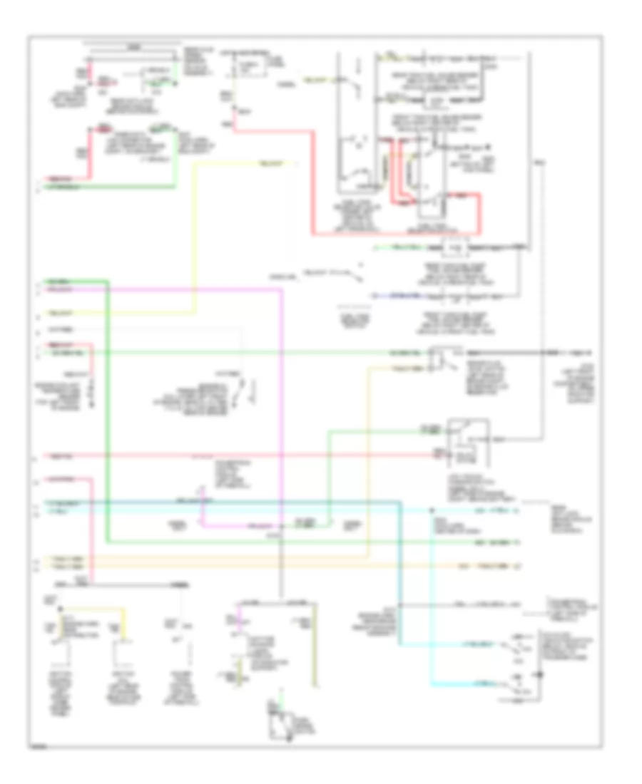
INSTRUMENT CLUSTER
Instrument Cluster Wiring Diagram (1 of 2) for Ford Cab & Chassis F350 1997

List of elements for Instrument Cluster Wiring Diagram (1 of 2) for Ford Cab & Chassis F350 1997:
- (behind bottom of right kick panel)
- (behind lower
- (left front of engine compt, on upper radiator support)
- 20 ohms
- 4x4 ind.
- 500 ohms
- A10
- A11
- A12
- A13
- A14
- Acc
- Anti-lock brake ind.
- B10
- B11
- B13
- Bat
- Brake fluid level
- Brake warning ind.
- C250 conn a
- C251 conn b
- C252 conn c
- Center of dash)
- Charge ind.
- Check engine ind.
- Chime module
- Coolant temp. gauge
- Diesel
- Diesel only
- Diesel warning lamps display
- Enable psom programming connector (below glove compt)
- Engine controls
- Engine warning ind.
- Except diesel
- Exterior lights system (multi-function switch)
- Fasten seat belt ind.
- Fuel gauge
- Fuel water switch (right side of engine, on bottom of fuel filter/heater)
- Fuse 10a
- Fuse 15a
- Fuse 4a
- Fuse panel
- G108
- G200 (behind bottom of left kick panel)
- G203
- Gas
- Gas only
- Generator/ voltage regulator
- Gnd
- Headlights system (multi-function switch)
- Hi beam ind.
- Hot at all times
- Hot in run
- Hot in run or start
- Hot w/ light sw in head or park
- Ign (run)
- Ignition switch
- Illumination lamps
- Instrument cluster
- Left turn ind.
- Lock
- Low range ind.
- Off
- Oil press. gauge
- Overheat warning switch (left front of engine)
- Plugged fuel filter ind.
- Plugged fuel filter switch (right side of engine, in fuel filter/heater housing)
- Powertrain control module (left side of firewall)
- Programmable speedometer/ odometer module
- Red
- Red/pnk
- Right turn ind.
- Run
- S102
- S117
- S202
- S206
- S214
- S215
- S216
- S218
- S242
- S246 (main harn, near b/o to spd ctrl amp)
- Solid state
- Speed control servo/ amplifier assembly (near brake master cylinder)
- Start
- Tachometer
- Test
- Volt- meter
- Vss input
- Vss output
- Vss return
- Wait-to-start ind.
- Warning
- Water-in- fuel ind.
- Water-in- fuel sensor (right side of engine, near fuel filter)
Instrument Cluster Wiring Diagram (2 of 2) for Ford Cab & Chassis F350 1997
List of elements for Instrument Cluster Wiring Diagram (2 of 2) for Ford Cab & Chassis F350 1997:
- (below right center of
- (below right rear of
- (left rear of engine
- 4x2
- 4x4
- 4x4 hi/low indicator switch (below vehicle, on front of transfer case)
- Brake fluid level switch (left rear of engine compt, on brake fluid reservoir)
- Compt, on bracket)
- Daytime running lamps module (on radiator support)
- Diesel
- Diesel only
- Engine coolant temperature sender (top left front of engine)
- Engine oil pressure switch (5.8l-lower left front of engine, near oil filter) (7.3l & 7.5l-top center rear of engine)
- Front
- Front tank fuel gauge sender
- Front tank fuel pump/ fuel gauge sender (below right center of vehicle, in front fuel tank)
- Fuel tank selector switch
- Fuel tank selector valve (under left center of vehicle, on left frame rail)
- Fuse 6 15a
- Fuse panel
- G108 (left front of engine compartment, on upper radiator support)
- G200 (bottom of left kick panel)
- Gas
- Gasoline
- Hot in acc or run
- Ignition coil (left rear of engine, near intake manifold)
- Ignition control module (left side of inner fender panel)
- Link connector
- Low
- Low vacuum warning switch (diesel only) (left side of engine compt, behind battery)
- Nca
- Only
- Park brake switch
- Power- train control module (left side of firewall)
- Powertrain control module (left side of firewall)
- Powertrain control module (left side of firewall)
- Rabs data
- Rear
- Rear anti-lock brake module (behind glove box)
- Rear axle speed sensor (on axle assembly)
- Rear tank fuel gauge sender
- Rear tank fuel pump/ fuel gauge sender (below right rear of vehicle, in rear fuel tank)
- Red
- Red/
- Red/ pnk
- Red/pnk
- S140
- S171 (engine harn, near distributor)
- S174 (engine harn, near brake resistor/diode assembly)
- S202
- S205
- S229
- S244 (main harn, center of dash)
- S247 (main harn, left rear of eng compt)
- S248 (main harn, left rear of eng compt)
- S400
- Solid state
- Vehicle, in front fuel tank)
- Vehicle, in rear fuel tank)
- W/ drl
- W/o drl