AIR CONDITIONING
Automatic A/C Wiring Diagram (1 of 2) for Honda CR-Z EX 2013

List of elements for Automatic A/C Wiring Diagram (1 of 2) for Honda CR-Z EX 2013:
- (in auxiliary under- hood relay box b) a/c diode a
- (in auxiliary under- hood relay box b) a/c diode b
- A/c compressor clutch (left front of engine)
- A/f sensor relay
- Ab3
- Air mix control motor (left side of hvac assembly)
- Automatic lighting/ sunlight sensor (top right side of dash)
- B10
- B24
- B33
- B34
- Blower motor relay
- C113
- C115
- C116
- C302
- Climate control unit
- Computer data lines system
- Defogger system
- Evaporator temperature sensor (upper right side of dash)
- Fuse 10 7.5a
- Fuse 26 10a
- Fuse 29 10a
- Fuse 30a
- Fuse 31 7.5a
- Fuse 57 30a
- Fuse 7.5a
- G502 (center of dash)
- Hot at all times
- Hot in on
- Hot in on or start
- Micu
- Mode control motor (upper left side of hvac assembly)
- Navigation system
- Pnk
- Power mirror/ rear window defogger switch
- Power mirror/ rear window defogger switch/ ind
- Recirculation control motor (right side of hvac assembly)
- Red
- Under-dash fuse/relay box (left end of dash)
- Y11
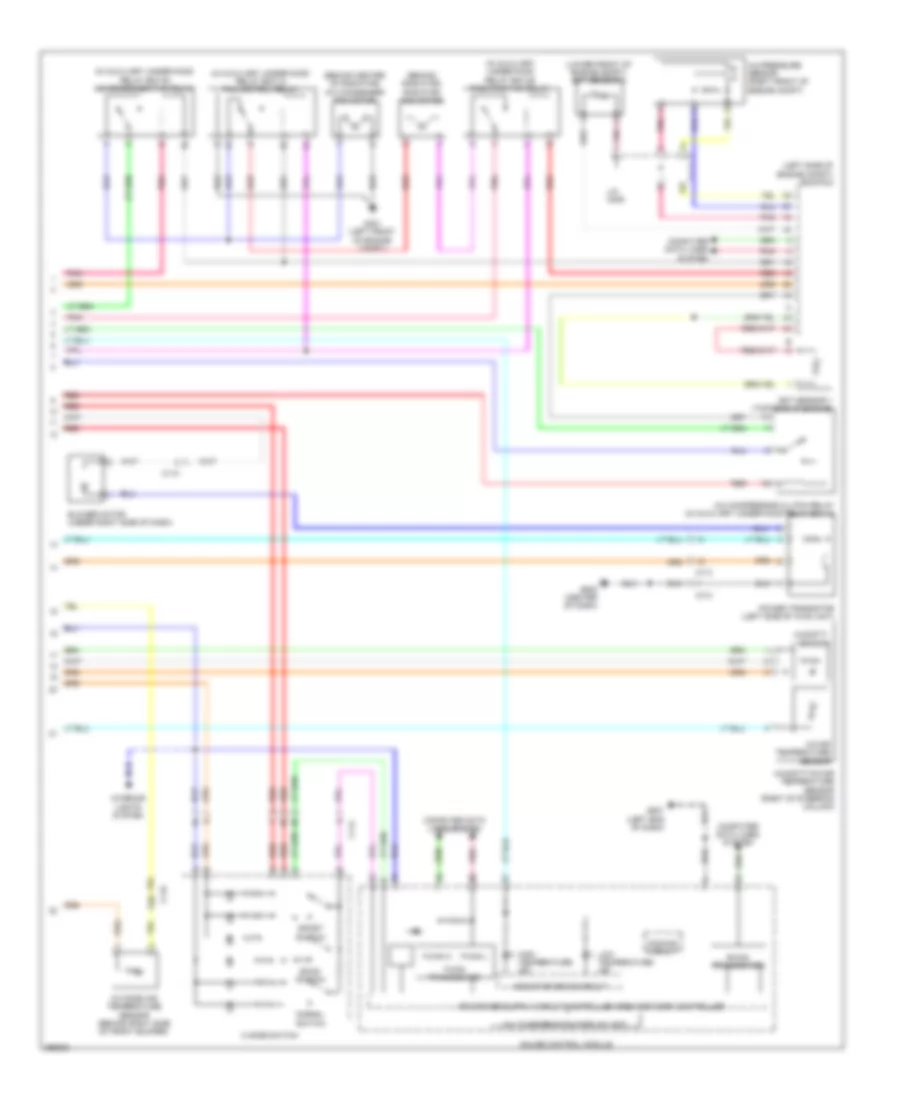
Automatic A/C Wiring Diagram (2 of 2) for Honda CR-Z EX 2013
List of elements for Automatic A/C Wiring Diagram (2 of 2) for Honda CR-Z EX 2013:
- (behind center of radiator) a/c condenser fan motor
- (behind radiator) radiator fan motor
- (in auxiliary under-hood relay box a) fan control relay
- (in auxiliary under-hood relay box b) a/c condenser fan relay
- (in auxiliary under-hood relay box b) radiator fan relay
- (left side of engine compt) ecm/pcm
- (lower front of engine compt) ect sensor 2
- 3 mode switch
- A/c compressor clutch relay (in auxiliary under-hood relay box a)
- A/c pressure sensor (right front of engine compt)
- B-can transceiver
- Blower motor (under right side of dash)
- C110
- C113
- C114
- C115
- Computer data lines system
- Dimming circuit
- Econ switch
- Ect sensor 1 (top rear of engine)
- F-can h
- F-can l
- F-can transceiver
- G401 (left front of engine compt)
- G501 (left end of dash)
- G502 (center of dash)
- Gauge control module
- High temperature ind
- Humidity sensor
- Humidity/in-car temperature sensor (right of steering column)
- In-car temperature sensor
- Indicator drive circuit
- Interior lights system
- J/c c006
- Low temperature ind
- Multi-information display unit
- Normal switch
- Outside air temperature sensor (behind right side of front bumper)
- Pnk
- Power transistor (left side of hvac unit)
- Red
- Sport switch