ANTI-THEFT
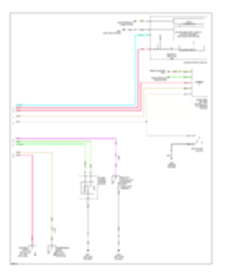
Forced Entry Wiring Diagram (1 of 2) for Honda CR-Z EX 2013

List of elements for Forced Entry Wiring Diagram (1 of 2) for Honda CR-Z EX 2013:
- A22
- A28
- Aa6
- B28
- B30
- C111
- C117
- Computer data
- D17
- D26
- D27
- D40
- Door lock knob
- Driver's door lock actuator/knob switch
- Driver's door unlock relay (left side of dash)
- Exterior lights system
- F10
- F11
- Fuse 10a
- Fuse 15a
- Fuse 20a
- Fuse 7.5a
- G501 (left end of dash)
- G502 (center of dash)
- Horns system
- Hot at all times
- Hot in on or start
- Key
- Lines system
- Lock
- Micu
- N10
- Passenger's door lock actuator/knob switch
- Pnk
- Q18
- Q28
- Red
- Trunk, tailgate, fuel doors system
- Under-dash fuse/relay box (left end of dash)
- Unlock
- Y14
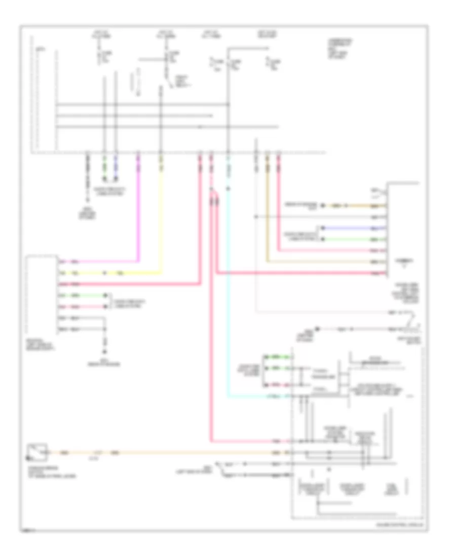
Forced Entry Wiring Diagram (2 of 2) for Honda CR-Z EX 2013
List of elements for Forced Entry Wiring Diagram (2 of 2) for Honda CR-Z EX 2013:
- (rear of engine) g101
- Antenna
- B-can transceiver
- Blinking circuit
- C118
- C302
- Computer data lines system
- Driver's door switch (on left "b" pillar)
- G403 (left side of dash)
- G501 (left end of dash)
- G502 (center of dash)
- Gauge control module
- Ignition key switch
- Immobilizer- keyless control unit (in steering column)
- Lock
- Passenger's door switch (on right "b" pillar)
- Pnk
- Power window master switch
- Security hood switch (on engine compt hood latch assembly)
- Security indicator led
- Unlock
Immobilizer Wiring Diagram for Honda CR-Z EX 2013
List of elements for Immobilizer Wiring Diagram for Honda CR-Z EX 2013:
- (rear of engine) g101
- A14
- Antenna
- B-can transceiver
- B10
- B22
- C118
- Compulsory turning off circuit
- Compulsory turning on circuit
- Computer data
- Computer data lines system
- Ecm/pcm (left side of engine compt)
- F-can h
- F-can l
- Fuel safe circuit
- Fuse 10a
- Fuse 15a
- Fuse 7.5a
- G101 (rear of engine)
- G501 (left end of dash)
- G502 (center of dash)
- Gauge control module
- Hot at all times
- Hot in on or start
- Ignition key switch
- Immobilizer system indicator
- Immobilizer- keyless control unit (in steering column)
- Indicator drive circuit
- Key
- Lines system
- Micu
- Parking brake switch (at base of park lever)
- Pgm-fi main relay 1
- Pnk
- Q18
- Tranceiver
- Under-dash fuse/relay box (left end of dash)