AIR CONDITIONING
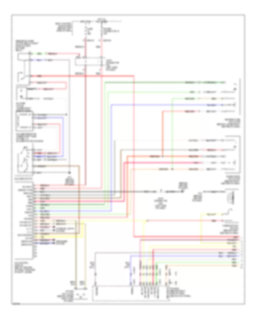
Automatic A/C Wiring Diagram (1 of 2) for Hyundai Tiburon GT 2006

List of elements for Automatic A/C Wiring Diagram (1 of 2) for Hyundai Tiburon GT 2006:
- (behind right center of dash) blend door actuator
- (beside blower motor, below right side of dash) blower relay
- (not
- A/c control module (below center of dash, forward of shift lever)
- A/c output
- A/c select
- Actuator
- Amb temp sens
- Ambient temperature sensor (behind center of front bumper)
- Aqs sensor
- Aqs sensor (left front of engine compartment)
- Bcm-ce
- Bcm-im
- Bcm-km
- Bcm-lm
- Blow fusible link 30a
- Blower motor (under right side of dash)
- Blr feed back
- Body control module box (behind left side of dash)
- Def
- Defogger
- Defogger ind
- Defogger sw
- E/r box (in left front corner of engine compt, behind battery)
- Feed back sig
- Fuse 10a
- G11 (behind center of dash)
- G12 (behind center of dash)
- G15 (on left front corner of engine compt)
- Ground
- Hi blwr ctrl
- High blower relay (beside blower motor, below right side of dash)
- Hot at all times
- Hot in on
- Humidity sensor
- Humidity sensor (on right rear of vehicle, above wheelwell)
- Ill+
- Ill-
- In-car sens in
- In-car sens out
- Intake actuator
- Interior lights system
- J/c e56
- J/c m36 (left side of dash)
- Joint connector m35 (left side of dash)
- M19-1
- M19-2
- Memory power
- Nca
- On input
- Photo sens +
- Photo sens -
- Pnk
- Power (5v)
- Power connector 10a
- Power transistor (under right side of dash, in blower motor housing)
- Pwr trans
- Red
- Sensor ground
- Sensor signal
- System
- Temperature actuator (behind lower right center of dash)
- Used)
- Vent
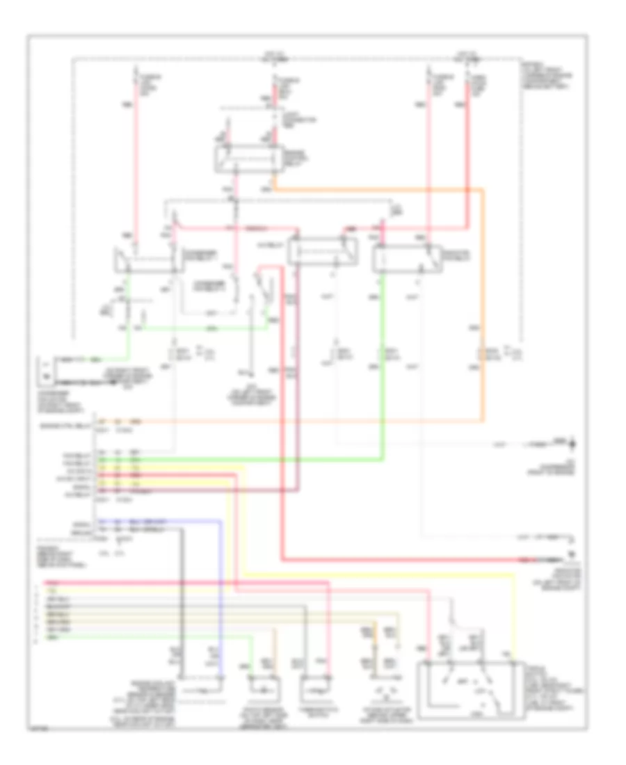
Automatic A/C Wiring Diagram (2 of 2) for Hyundai Tiburon GT 2006
List of elements for Automatic A/C Wiring Diagram (2 of 2) for Hyundai Tiburon GT 2006:
- (2.0l: on rear of engine, near coolant outlet)
- (on right front corner of engine compartment) g16
- (or
- 2.0l
- 2.7l
- A/c compressor (front of engine)
- A/c relay
- A/c sig in
- A/c sw input
- C133-2
- C133-3
- C133-4
- C33-1
- Condenser fan motor (on right front of engine compt)
- Condenser fan relay 1
- Condenser fan relay 2
- E/r box (in left front corner of engine compartment, behind battery)
- Ec01
- Ec01 ec101
- Ec02
- Ec101
- Ec102
- Engine control relay
- Engine coolant temperature sensor & sender (2.7l: on top left rear of cylinder head, near coolant outlet)
- Engine ctrl relay c33-1
- Fan relay
- Fusible link (cond) 30a
- Fusible link (ecu) 30a
- Fusible link (rad) 30a
- G15 (on left front corner of engine compartment)
- Ground
- High
- Horn/ a/con fuse 15a
- Hot at all times
- Intake actuator (behind upper right side of dash)
- J/c e56
- Joint connector e56
- Low
- Mid
- Nca
- Pcm/ecm (behind right side of dash, above kick panel)
- Photo sensor (on top left side of dash, near defroster vent)
- Pnk
- Radiator fan motor (on left front of engine compt)
- Radiator fan relay
- Red
- Signal
- Thermostatic switch
- Triple switch (2.0l: on a/c line, near right front strut tower) (2.7l: on a/c line, at front of engine compt)
Manual A/C Wiring Diagram (1 of 2) for Hyundai Tiburon GT 2006
List of elements for Manual A/C Wiring Diagram (1 of 2) for Hyundai Tiburon GT 2006:
- (behind center of dash) g11
- (beside blower motor, below right side of dash) blower relay
- 2.0l
- 2.7l
- A/c control module (below center of dash, forward of shift lever)
- A/c on
- A/c rly
- A/c sig
- A/c sw on
- Bcm-im
- Bcm-km
- Blend door actuator (behind right center of dash)
- Blower motor (under right side of dash)
- Blower resistor (under right side of dash, in blower motor housing)
- Blower switch
- Blr (common)
- Body control module box (behind left side of dash)
- C fan sig
- C133-2
- C133-3
- C133-4
- C33-1
- Cool
- Def
- Defog ind
- Defog sw
- Defogger system
- Eng relay
- F/b gnd
- F/back
- Fan relay
- Fuse 10a
- G12 (behind center of dash)
- Ground
- Hot at all times
- Hot in on
- Iii
- Iiii
- Ill (+)
- Ill (-)
- Intake act
- Intake actuator (behind upper right side of dash)
- Interior lights system
- Joint connector m35 (left side of dash)
- Joint connector m36 (left side of dash)
- Memory pwr
- Nca
- Off
- On input
- Pbr
- Pcm/ecm (behind right side of dash, above kick panel)
- Pnk
- Power connector 18 10a
- Red
- Signal
- Temperature actuator (behind lower right center of dash)
- Thermistor
- Thermostatic switch (behind right center of dash)
- Vcc
- Vent
- Warm
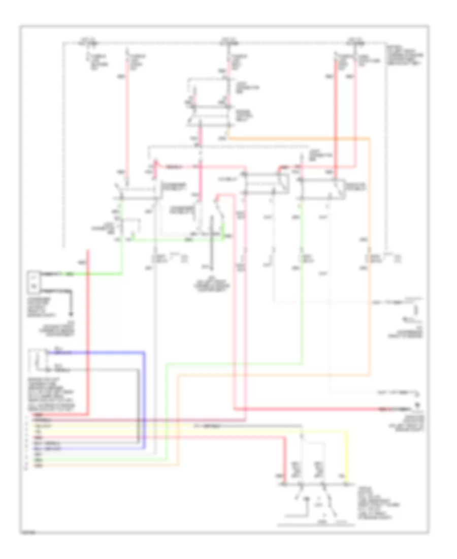
Manual A/C Wiring Diagram (2 of 2) for Hyundai Tiburon GT 2006
List of elements for Manual A/C Wiring Diagram (2 of 2) for Hyundai Tiburon GT 2006:
- (2.0l: on rear of engine, near coolant outlet)
- 2.0l 2.7l
- A/c compressor (front of engine)
- A/c relay
- Condenser fan motor (on right front of engine compt)
- Condenser fan relay 1
- Condenser fan relay 2
- E/r box (in left front corner of engine compartment, behind battery)
- Ec01 ec101
- Ec02 ec102
- Engine control relay
- Engine coolant temperature sensor & sender (2.7l: on top left rear of cylinder head, near coolant outlet)
- Fusible link (blower) 30a
- Fusible link (cond) 30a
- Fusible link (ecu) 30a
- Fusible link (rad) 30a
- G15 (on left front corner of engine compartment)
- G16 (on right front corner of engine compartment)
- High
- Horn/ a/con fuse 15a
- Hot at all times
- Joint connector e56
- Low
- Mid
- Nca
- Pnk
- Radiator fan motor (on left front of engine compt)
- Radiator fan relay
- Red
- Triple switch (2.0l: on a/c line, near right front strut tower) (2.7l: on a/c line, at front of engine compt)