CRUISE CONTROL
Cruise Control Wiring Diagram for Hyundai Tiburon GT 2006
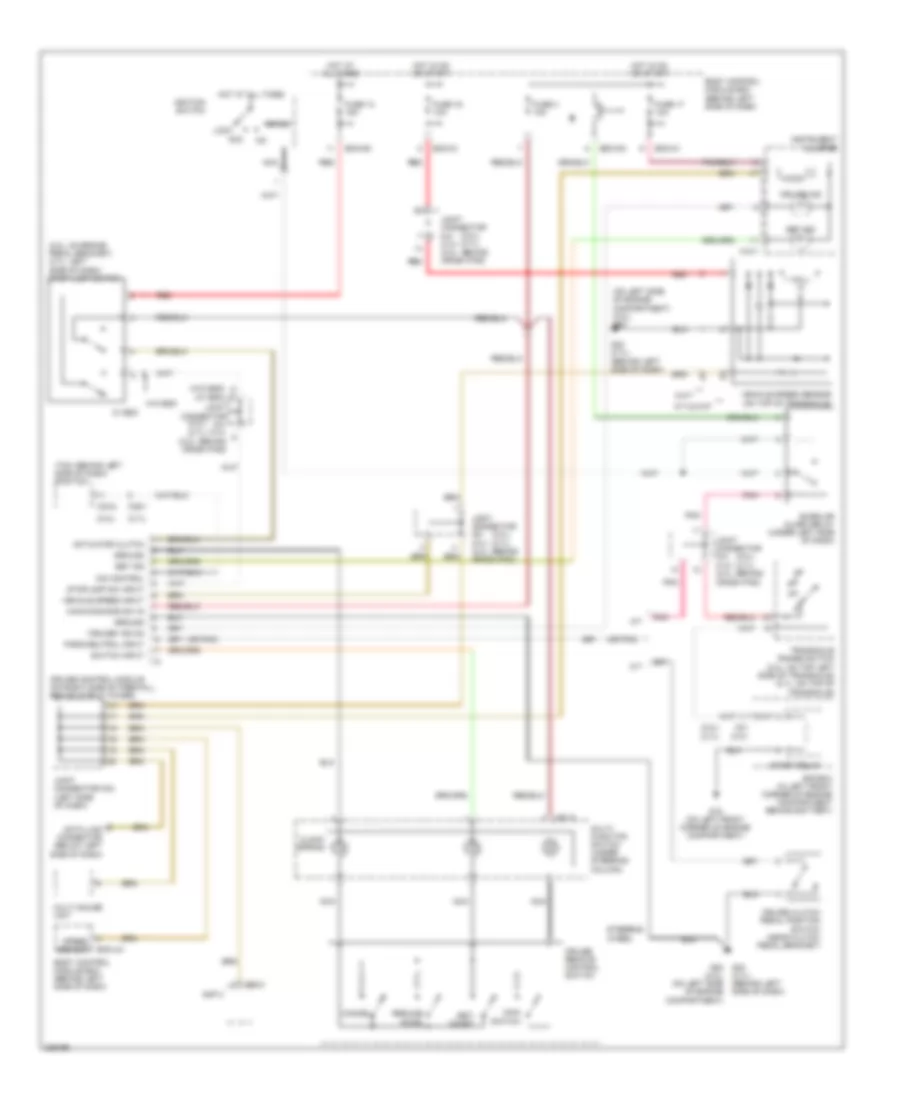
List of elements for Cruise Control Wiring Diagram for Hyundai Tiburon GT 2006:
- "cruise" ind on
- (2.0l)
- (2.0l) (2.7l)
- (2.0l: on brake pedal bracket) (2.7l: left side of dash) stop lamp switch
- (2.7l)
- (on left side of engine compartment) (2.0l) g20
- (or pnk)
- (tcm: behind left side of dash) pcm/tcm
- (w/o esc) (w/ esc)
- 5 m/t
- A/t
- A/t & 6 m/t
- Acc
- Actuator clutch
- Amp 2
- Bcm-im
- Bcm-jm
- Bcm-km
- Body control module box (behind left side of dash)
- Burglar alarm relay (under left side of dash)
- C01
- C101
- C33-2
- C36-1
- Cancel
- Clock spring
- Cruise clutch pedal position switch (near clutch pedal bracket)
- Cruise control module (on right side of firewall, behind strut tower)
- Cruise ind
- Cruise remote control switch
- Data link connector (below left side of dash)
- E/r box (in left front corner of engine compartment behind battery)
- Fuse 13 15a
- Fuse 16 10a
- Fuse 17 10a
- Fuse 3 10a
- G15 (on left front corner of engine compartment)
- G20 (2.0l) (on left side of engine compartment)
- G23 (2.7l) (behind left side of dash)
- Ground
- Hall ic
- Hot at all times
- Hot in on or start
- Ignition switch
- Instrument cluster
- Joint connector c41 c141 (2.0l: behind crash pad)
- Joint connector m34 (left side of dash)
- Lock
- M/t
- M01-3
- M10-1
- M62-2
- Main switch
- Main/command sw in
- Micom
- Multi gauge unit
- Multi- function switch (under steering column)
- Nca
- O/d control
- Park/neutral input
- Pnk
- Red
- Resume/ accel
- Set ind
- Set/ coast
- Speed sensor
- Start
- Start relay
- Steering wheel
- Stoplamp sw input
- Switch input
- Transaxle range switch (2.0l: on top left side of transaxle) (2.7l: on top of transaxle)
- Vehicle speed input
- Vehicle speed sensor (on top of transaxle)
- W/ esc
- W/o esc
 English