AIR CONDITIONING
Compressor Wiring Diagram for Isuzu i-290 S 2008

List of elements for Compressor Wiring Diagram for Isuzu i-290 S 2008:
- 4.3l
- 4.8l, 5.3l & 6.0l
- 5v ref
- 6.6l
- A/c cmprsr fuse 57 15a
- A/c compressor clutch (4.3l: at left front of engine) (4.8l, 5.3l & 6.0l: at lower right front of engine) (6.6l: top front of engine)
- A/c comprsr relay 74
- A/c low pressure switch (on side of accumulator)
- A/c refrigerant pressure sensor
- A/c request sig
- Bi-lev
- Body control module (bcm) (behind lower right side of dash)
- Body fuse block (under left front seat)
- Clutch rly ctrl
- Computer data lines system
- Def
- Engine control module (ecm) (left side of engine compt)
- G102 (6.6l: left front lower side of the engine block) (except 6.6l: on left rear of engine)
- G304 (behind right kick panel)
- Gmlan (+)
- Gmlan (-)
- Heat
- Heat/def
- Hot at all times
- Hot in run
- Hvac 2 fuse 1 10a
- Hvac control assembly
- J102
- J249
- Logic
- Low ref
- Max norm
- Off
- Press sens
- Tan
- Underhood fuse block (on left side of engine compt)
- Vent
- W/ electric rear window defogger & power mirrors
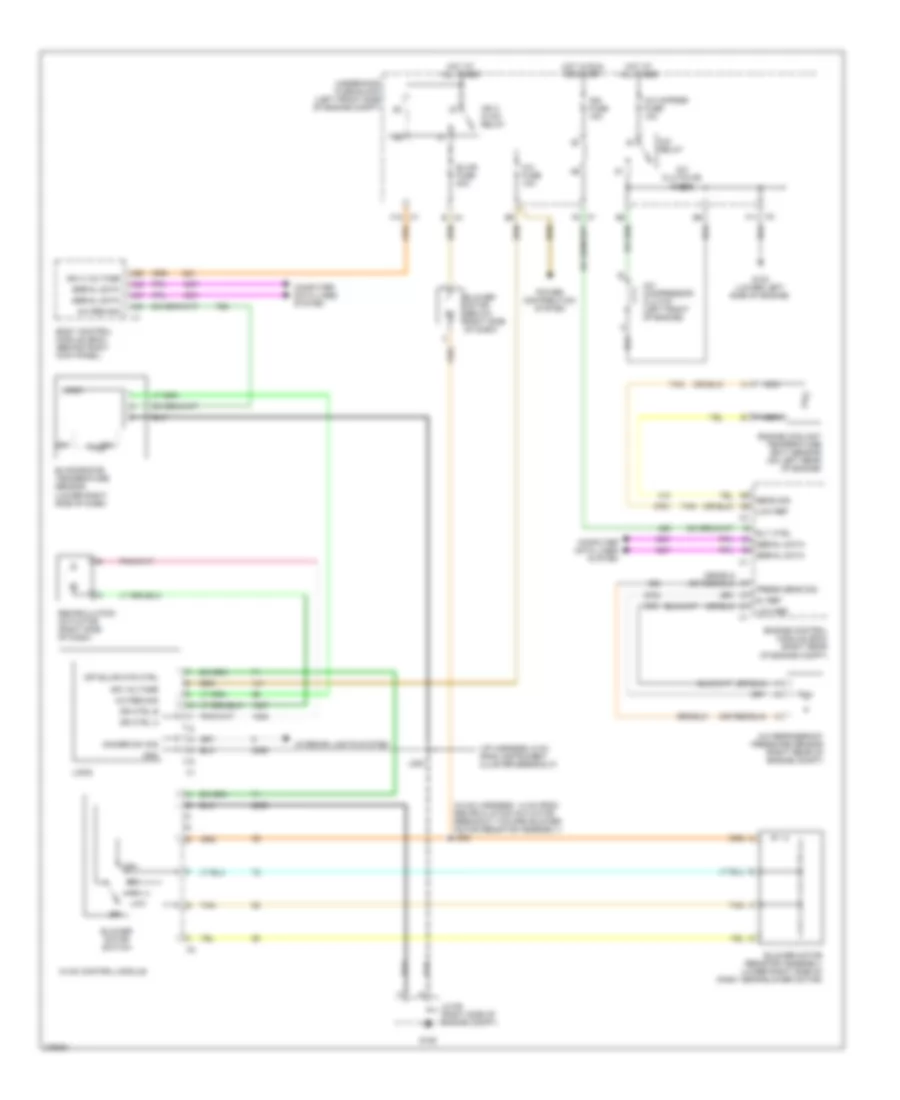
Manual A/C Wiring Diagram for Isuzu i-290 S 2008
List of elements for Manual A/C Wiring Diagram for Isuzu i-290 S 2008:
- (hvac harness, 14 cm from recirculation actuator breakout toward blower motor resistor assembly) j202
- (i/p harness, 6 cm from instrument cluster breakout)
- 5v ref
- A/c clutch 65 diode
- A/c cmprsr fuse 10a
- A/c compressor clutch (left front of engine)
- A/c fuse 10a
- A/c refrigerant pressure sensor (right rear of engine compt)
- A/c relay
- A/c req sig
- A26
- A42
- A43
- A47
- B x4
- Blower motor (below right side of dash)
- Blower motor resistor assembly (lower right side of dash, near blower motor)
- Blower motor switch
- Blwr fuse 30a
- Body control module (bcm) (behind right kick panel)
- Computer data lines system
- Dimmer sw sig
- Dr ctrl a
- Dr ctrl b
- Engine control module (ecm) (right rear of engine compt)
- Engine coolant temperature (ect) sensor (on left rear of engine)
- Evaporator temperature sensor (lower right side of dash)
- F10 x7
- G103 (lower left side of engine)
- G106
- Gnd
- High
- Hot at all times
- Hot in run or start
- Hvac control module
- Ign 3 hvac relay
- Ign 3 voltage
- Ign fuse 15a
- Ign voltage
- Interior lights system
- J200
- Jx106 (right side of engine compt)
- Logic
- Low
- Low ref
- Nca
- Off
- Off blwr mtr ctrl
- Power distribution system
- Press sens sig
- Recirculation actuator (right side of dash)
- Rly ctrl
- Sens sig
- Serial data
- Tan
- Underhood fuse block (left front side of engine compt)
- X2 f11
- X7 f5