AIR CONDITIONING
Automatic A/C Wiring Diagram for Mazda 5 Touring 2007

List of elements for Automatic A/C Wiring Diagram for Mazda 5 Touring 2007:
- (behind center of dash) passenger compartment temperature sensor
- 1an
- 1ap
- 2aa
- 2ak
- A/c fuse 10a
- A/c relay
- Air flow mode actuator (behind left center of dash)
- Air intake actuator (behind right side of dash)
- Air mix actuator (behind right center of dash)
- Ambient temperature sensor (behind center of grille)
- Bcm (behind right side of dash)
- Blower fuse 40a
- Blower motor (behind center of dash)
- Blower relay (in main fuse block)
- Climate control module
- Cold
- Computer data lines system
- Cooling fan motor
- Cooling fan relay
- Def
- Defogger system
- Eng fuse 5a
- Engine coolant temperature sensor (top rear of engine)
- Evaporator temperature sensor (under center of dash)
- Fan control module (left front of engine compt)
- Fan fuse 30a
- Fuse block (behind right end of dash)
- G1 (behind left headlight)
- G4 (behind left end of dash)
- G6 (behind right end of dash)
- High & low pressure
- Hot
- Hot at all times
- Hot in run
- Hot in run or start
- Interior lights system
- J/c c-11 (behind right end of dash)
- J/c c-12 (behind center of dash)
- Jc-g01
- Jc-g02
- Mag fuse 10a
- Magnetic clutch (on a/c compressor)
- Main fuse block (left side of engine compt)
- Medium pressure
- Nca
- Power metal oxide semiconductor field effect transistor (power mos fet) (behind center of dash)
- Powertrain control module (rear of engine compt)
- Red
- Refrigerant pressure switch (right rear of engine compt)
- Solar radiation sensor (under top center of dash)
- Thermal protector
- Vent
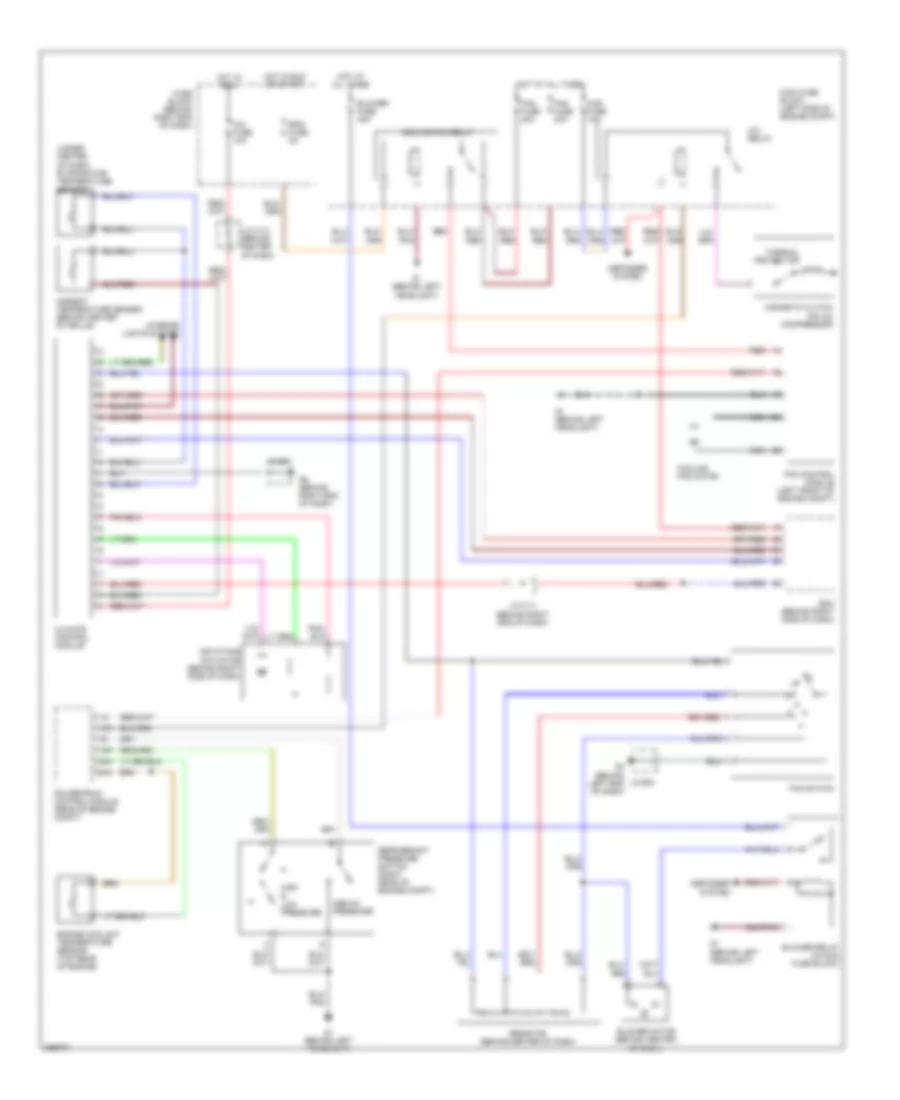
Manual A/C Wiring Diagram for Mazda 5 Touring 2007
List of elements for Manual A/C Wiring Diagram for Mazda 5 Touring 2007:
- (under center of dash) evaporator temperature sensor
- 1an
- 1ap
- 2aa
- 2ak
- A/c fuse 10a
- A/c relay
- Air intake actuator (behind right side of dash)
- Ambient temperature sensor (behind center of grille)
- Bcm (behind right side of dash)
- Blower fuse 40a
- Blower motor (behind center of dash)
- Blower relay (in main fuse block)
- Climate control module
- Cooling fan motor
- Cooling fan relay
- Defogger system
- Eng fuse 5a
- Engine coolant temperature sensor (top rear of engine)
- Fan control module (left front of engine compt)
- Fan fuse 30a
- Fan switch
- Fuse block (behind right end of dash)
- G1 (behind left headlight)
- G4 (behind left end of dash)
- G6 (behind right end of dash)
- High & low pressure
- Hot at all times
- Hot in run
- Hot in run or start
- Interior lights system
- J/c c-11 (behind right end of dash)
- J/c c-12 (behind center of dash)
- Jc-g01
- Jc-g02
- Mag fuse 10a
- Magnetic clutch (on a/c compressor)
- Main fuse block (left side of engine compt)
- Medium pressure
- Nca
- Powertrain control module (rear of engine compt)
- Red
- Refrigerant pressure switch (right rear of engine compt)
- Resistor (behind center of dash)
- Thermal protector