
SHIFT INTERLOCK
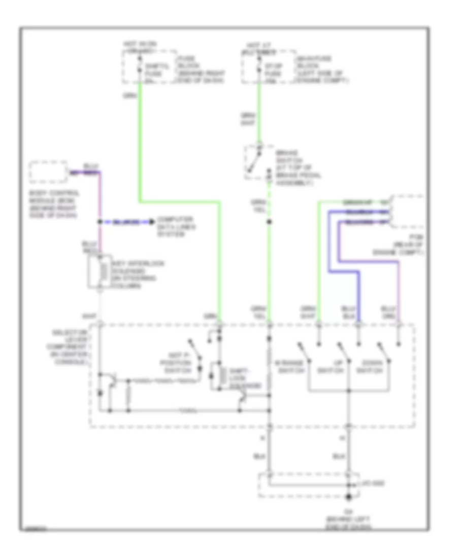
Shift Interlock Wiring Diagram for Mazda 5 Touring 2007
List of elements for Shift Interlock Wiring Diagram for Mazda 5 Touring 2007:
AIR CONDITIONINGBODY CONTROL MODULESANTI-THEFTANTI-LOCK BRAKESCOMPUTER DATA LINESEXTERIOR LIGHTSCOOLING FANCRUISE CONTROLELECTRONIC POWER STEERINGDEFOGGERSGROUND DISTRIBUTIONENGINE PERFORMANCEHEADLIGHTSINTERIOR LIGHTSHORNINSTRUMENT CLUSTERPOWER DISTRIBUTIONNAVIGATIONPOWER DOOR LOCKSPOWER SEATSPOWER MIRRORSSHIFT INTERLOCKSTARTING/CHARGINGPOWER TOP/SUNROOFRADIOPOWER WINDOWSSUPPLEMENTAL RESTRAINTSTRANSMISSIONTRUNK, TAILGATE, FUEL DOORWIPER/WASHERWARNING SYSTEMS