AIR CONDITIONING
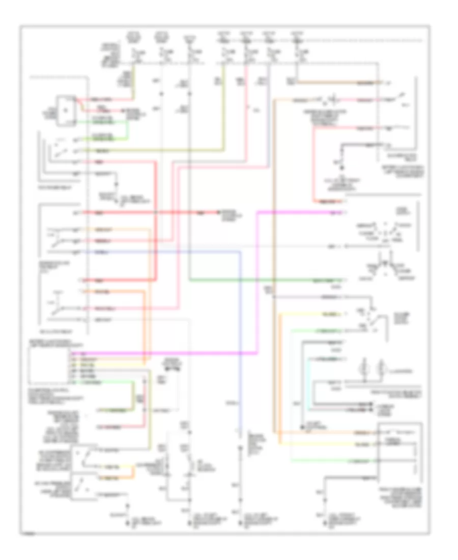
Manual A/C Wiring Diagram for Mazda B3000 Dual Sport 2003
List of elements for Manual A/C Wiring Diagram for Mazda B3000 Dual Sport 2003:
- (4.0l: at left front corner of engine compt) g3
- (4.0l: at right rear corner of engine compt) g5
- (4.0l: behind left headlight) g1
- (at left kick panel) g7
- 2.3l
- A/c
- A/c clutch relay
- A/c clutch solenoid
- A/c compressor clutch diode
- A/c compressor cycling switch (in right side of engine compt, on a/c accumulator)
- A/c high pressure switch (near left side of engine)
- Battery junction box (left rear of engine compartment)
- Battery junction box (left rear of engine compt)
- Blower motor relay
- Blower motor switch
- Central junction box (behind left side of dash)
- Defrost
- Engine controls system
- Engine coolant temperature (ect) sensor (3.0l, 4.0l) (3.0l: on top left front of engine) (4.0l: on top front center of engine)
- Engine cooling fan motor (2.3l)
- Engine cooling fan relay (2.3l)
- Floor
- Flr/def
- Front function selector switch assembly
- Front heater blower motor resistor (right rear of engine compartment, near blower motor)
- Fuse 10a
- Fuse 20a
- Fuse 25a
- Fuse 30a
- Fuse 40a
- Fuse 7.5a
- G-232
- G-233
- G-234
- G3 (4.0l: at left front corner of engine compt)
- Heater blower motor (right rear of engine compt, on firewall)
- Hot at all times
- Hot in run
- Hot in run or start
- Illumination
- Interior lights system
- Max a/c
- Med hi
- Med lo
- Mode switch
- Off
- Panel
- Pcm power diode
- Pcm power relay
- Powertrain control module (pcm) (right rear of engine compt, through firewall)
- Red
- Thermal limiter
 English