AIR CONDITIONING
Automatic A/C Wiring Diagram (1 of 2) for Mercedes-Benz CLK550 2008

List of elements for Automatic A/C Wiring Diagram (1 of 2) for Mercedes-Benz CLK550 2008:
- 12v
- 15 ges
- C15
- C19
- Can-b h
- Can-b l
- Comfort aac control sun sensor (center of engine hood)
- Comfort aac multi-function sensor (right rear of engine compt)
- Comfort aac pushbutton control module
- Computer data lines system
- Data out
- Evaporator temperature sensor (under left side of dash)
- Fresh air/recirculated air flaps actuator motor (behind right side of dash)
- Front sam control module w/ fuse & relay module (left rear of engine compt)
- Fuse 15a
- Fuse 40a
- Fuse 7.5a
- Hot at all times
- Hot w/ circuit 15 relay power energized
- Instrument cluster
- Interior fuse box (left side of dash)
- Left blending air flap actuator (behind left side of dash)
- Left defroster vent flap actuator motor (behind left side of dash)
- Left footwell flap actuator motor (behind left side of dash)
- Left fresh air flap actuator (behind center of dash)
- Multiplex
- Nca
- Refrigerant pressure & temperature sensor (behind left side of front bumper)
- Right blending air flap actuator (behind glove box)
- Right defroster vent flap actuator motor (behind center of dash)
- Right footwell flap actuator motor (under center of dash)
- Right fresh air flap actuator (behind center of dash)
- Signal
- Upper control panel control module
- W16/4 (right front of engine compt)
- W28/1 (at left doorsill)
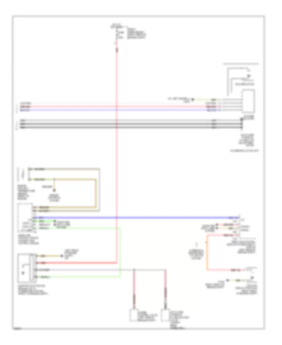
Automatic A/C Wiring Diagram (2 of 2) for Mercedes-Benz CLK550 2008
List of elements for Automatic A/C Wiring Diagram (2 of 2) for Mercedes-Benz CLK550 2008:
- (at left doorsill) w28/1
- (left front of engine compt) w9
- A t lues
- A/c recirculation unit
- Activated charcoal filter flap adjustment motor
- Activated charcoal filter shutoff valve (in right rear wheelwell)
- Blower motor
- Blower regulator
- C15
- C18
- C20
- Can-b h
- Can-b l
- Can-c h
- Can-c l
- Computer data lines system
- Coolant circulation pump (right front of engine compt)
- Electric suction fan engine & ac w/ integrated control (front of engine compt)
- Engine controls system
- Engine coolant temperature sensor (front of engine)
- Front prefuse box (right rear of engine compt)
- Front sam control module w/fuse & relay module (left rear of engine compt)
- Fuse 125a
- Hot at all times
- Lin
- Me-sfi (me) control module (in front sam control module)
- Nca
- Purge control valve (left side of engine compt)
- Red
- W/ residual engine heat utilization system
- W16/4 (right front of engine compt)